Close
0%
0%

Tornillo de escritorio - Bench Vise

Tornillo de escritorio; emulando parcialmente el diseño de tornillos de herrero.

Similar projects worth following
Tornillo de escritorio que emula el diseño de tornillo de herrero, las piezas principales fueron impresas en 3D

DESCRIPCIONES EN ESPAÑOL E INGLÉS

DESCRIPTION IN SPANISH AND ENGLISH

ESPAÑOL

Proyecto realizado en el marco del desarrollo del curso Procesos de Manufactura de la Facultad de Ciencias Físicas y Matemáticas de la Universidad de Chile.

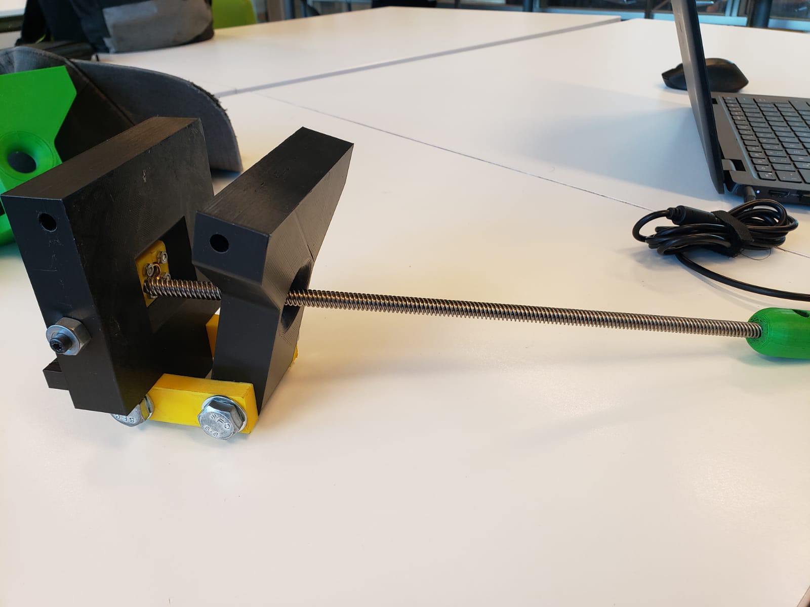
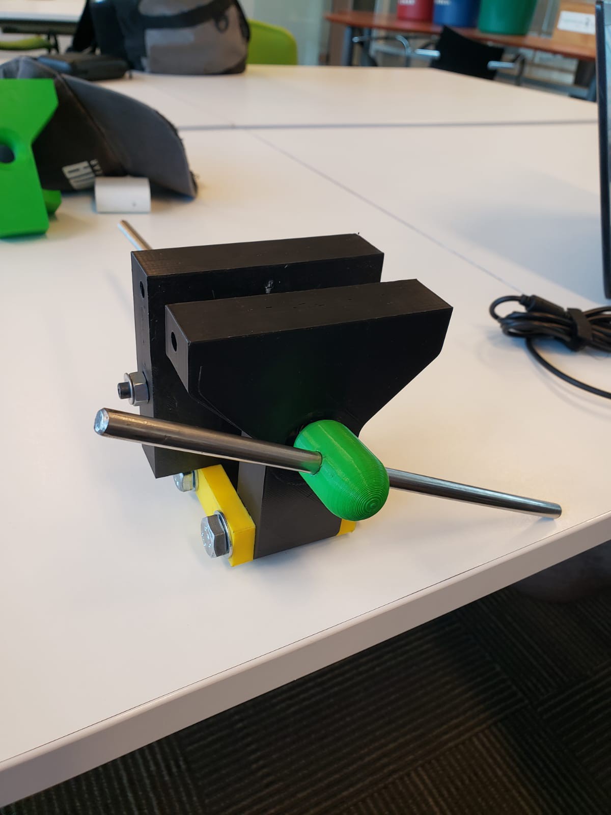
Se trata de un tornillo de escritorio emulando el funcionamiento de un tornillo de herrero, donde el mecanismo de apertura no es axial sino que se abre progresivamente siguiendo una apertura angular.

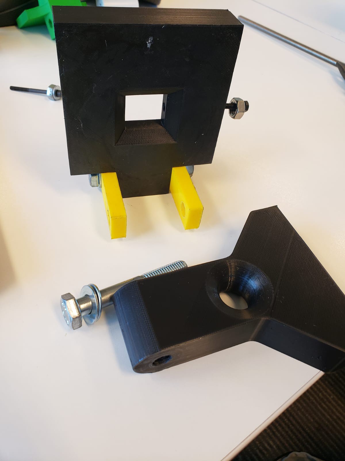
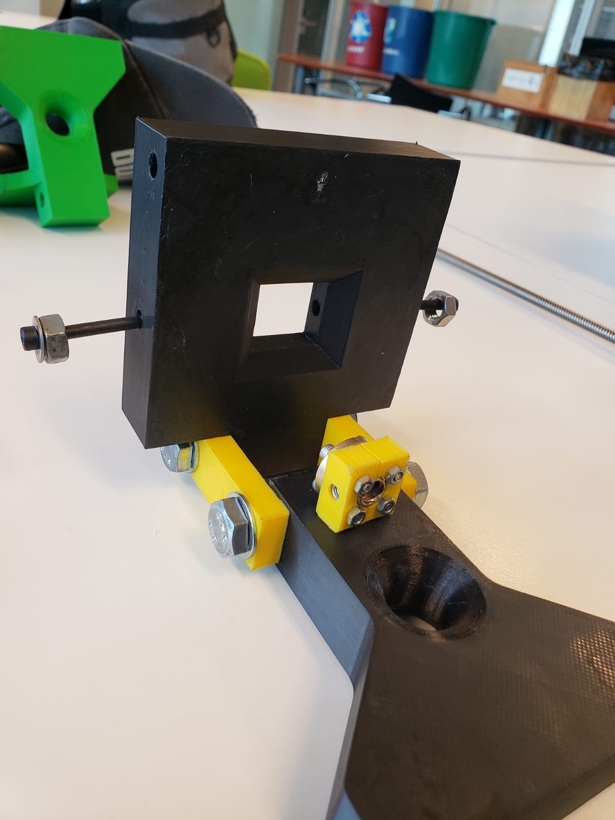
Para esto el diseño utiliza una pata fija y una móvil, ambas impresas en 3D; la fija, como indica su nombre, tiene que ser apernada a la mesa. Entre ambas patas se encuentra un tornillo ACME 8mm y su respectiva tuerca T8, las mismas utilizadas en las máquinas de impresión 3D.

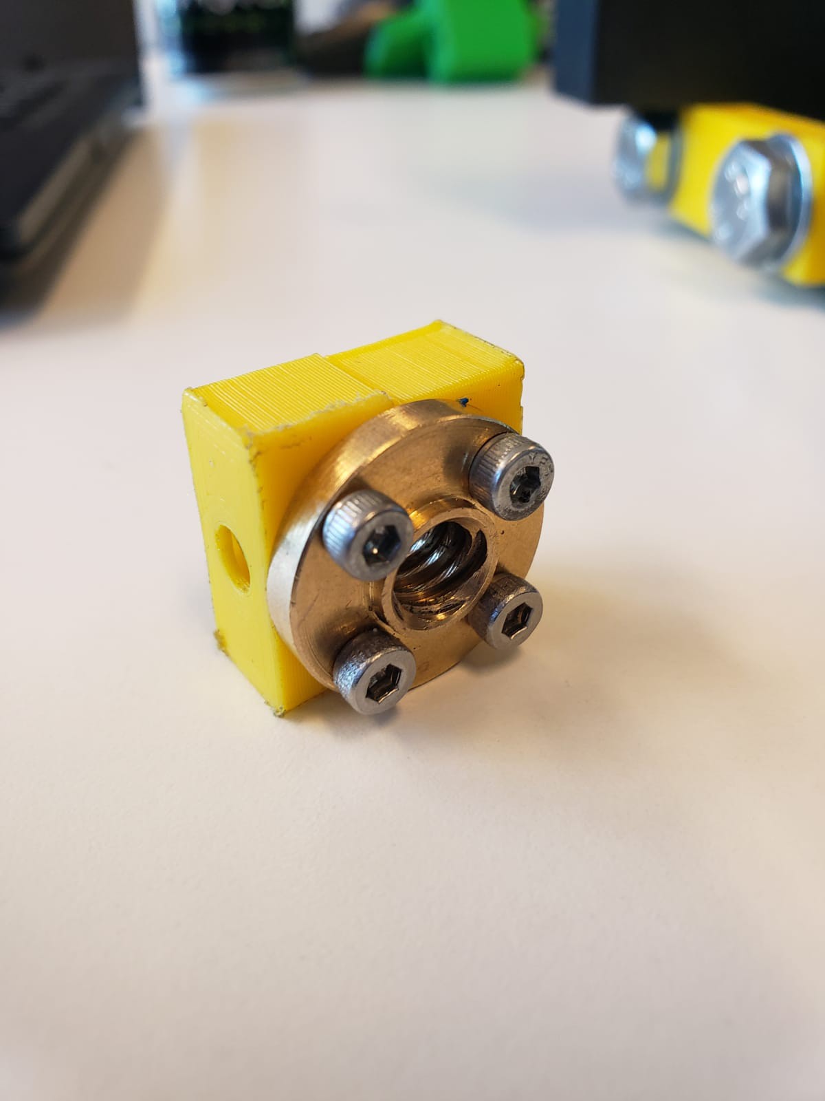
Los agujeros de las piezas no son exactamente de 8mm, por lo contrario son más grandes, para permitir el movimiento angular del tornillo; por el lado de la pata fija existe una pequeña pieza cuadrada que permite el movimiento de la tuerca pero evitando el movimiento en la dirección axial paralela al tornillo. En el extremo de la pata móvil del tornillo se encuentra una pieza denominada "masa", la cual al apretarse el tornillo empieza a empujar la pata hasta que se cierre.

Como bisagra existen 2 placas perforadas también impresas en 3D, por las cuales se hacen pasar 2 pernos de 10mm.

ENGLISH

Project framed within the subject Procesos de Manufactura from the Facultad de Ciencias Físicas y Matemáticas de la Universidad de Chile.

It´s a bench vise evoking the design of a blacksmith vise, where the aperture mechanism isn't axial; it opens progressively following and angular movement.

For this, the design uses a stationary and a moving jaw, both 3D printed; the stationary one, as it is indicated by its name, has to be fixed to the bench. Between both jaws there is an ACME 8mm bolt and its respective T8 nut, the same that are used for 3D printers.

The holes in both jaws aren't exactly 8mm in diameter, on the contrary they are way bigger, this is in order to allow the angular movement of the vise; on the side of the stationary jaw exists a small squared component that allows some movement on the bolt while limiting its axial movement parallel to the bolt. On the moving jaw side of the bolt, there is a part denominated "mass", which pushes the jaw when the bolt is tightened.

2 3D printed sheets are used as hinges; through which two 10mm bolts are placed.

mitad abrazadera tuerca.stl

Archivo .stl de pieza auxiliar .stl file of auxiliary piece

Standard Tesselated Geometry - 51.84 kB - 12/02/2022 at 19:04

Download

masa tornillo.stl

Archivo .stl de masa .stl file of mass

Standard Tesselated Geometry - 410.43 kB - 12/02/2022 at 19:04

Download

ensamble.stl

Archivo .stl de ensamble completo, para propósitos ilustrativos. .stl file of whole assembly, only for illustrative purposes

Standard Tesselated Geometry - 3.95 MB - 12/02/2022 at 19:03

Download

pata fija.stl

Archivo .stl de pata fija .stl file stationary jaw

Standard Tesselated Geometry - 63.75 kB - 12/02/2022 at 19:03

Download

placa lateral.stl

Archivo .stl de placa lateral .stl file hinge piece

Standard Tesselated Geometry - 20.59 kB - 12/02/2022 at 19:03

Download

View all 8 files

  • 1 × Pata fija - Stationary jaw Impresa en 3D, 233 gramos, ~16 horas de impresión. / 3D printed, 233 grams, ~16 hours of printing time
  • 1 × Pata móvil - Moving Jaw Impresa en 3D, 137 gramos, ~9 horas de impresión. / 3D printed, 137 grams, ~9 hurs printing time
  • 2 × Placas para bisagra - Hinge sheets impresa en 3D
  • 1 × Tornillo ACME 8mm - ACME 8mm Bolt
  • 1 × Tuerca T8 - T8 nut

View all 11 components

  • 1
    Proceso de impresión - Printing process

    En la publicación se encuentran los archivos .STL de todas las piezas a imprimir; se detallan los aspectos relevantes de configuración de cada una:

    • Pata fija: 20% infill
    • Pata móvil: 20% infill
    • Placas para bisagra: 40% infill
    • Piezas auxiliares: 10% infill
    • Masa: 10% infill

    In the documentation you can find every .STL file nedeed for the printing process. Relevant aspects of the process are listed below:

    • Stationary Jaw: 20'% infill
    • Moving Jaw: 20% infill
    • Hinge sheets: 40% infill
    • Auxiliary pieces: 10% infill
    • Mass: 10% infill
  • 2
    Ensamble - Assembly

    Primero se atornillan las piezas auxiliares a la tuerca T8 mediante 4 pernos M3.

    Se hace pasar uno de los tornillos de 10mm por una de las placas laterales y posteriormente por una de las patas, se atornillan y se repite el proceso con la otra pata.

    Luego mediante el uso de pernos M5 se atornilla el conjunto pieza auxiliar-tuerca al centro de la pata fija.

    Luego de eso se hace pasar el tornillo de 8mm a través del agujero de ambas patas y se atornilla a la tuerca. Posteriormente se pega la masa al tornillo con el uso de pegamento epóxico.

    Finalmente se hace pasar el fierro para el mango.

    First of all, the auxiliary pieces are bolted on the T8 nut using 4 M3 nuts. One of the 10mm nuts is placed through the hinge piece and one of the jaws, it is bolted on, and the process is repeated with the other jaw.

    After that, using M5 nuts, the aforementioned nut-auxiliary piece set is bolted on the stationary jaw.

    Then, the 8mm bolt is placed though the perforations of both jaws and is bolted on the nut. Afterwards, the mass is glued to the bolt using epoxy glue.

    Finally, the steel bar is placed through the mass in order to work as a handle.

View all instructions

Enjoy this project?

Share

Discussions

Pascal Griott wrote 12/02/2022 at 19:41 point

Para futuras iteraciones se debe mejorar las patas, de tal forma que puedan sujetar de mejor manera el objeto. Además de eso sería bueno hacer las placas laterales un poco más largas para permitir mayor apertura.

For future iterations it is a must to upgrade the jaws; they should be able to better grip the object. Moreover it would be good to fabricate longer side plates in order to accomodate a bigger aperture.

  Are you sure? yes | no

Similar Projects

Does this project spark your interest?

Become a member to follow this project and never miss any updates