The clock is made using arduino and other components as mentioned the files and all pictures are attached below
the control of the clock is done by arduino or you can use 74HC595 Drivers for easy control
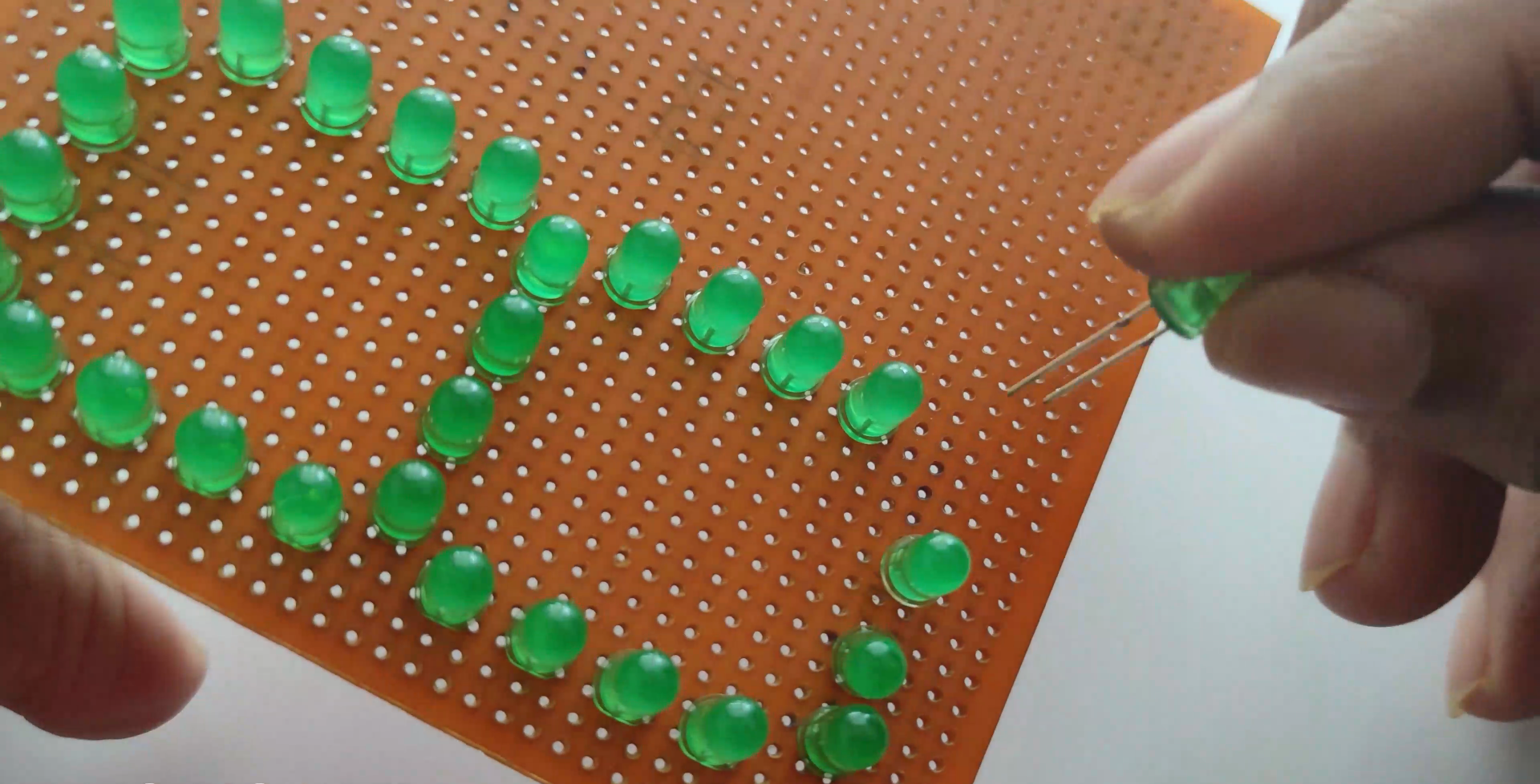
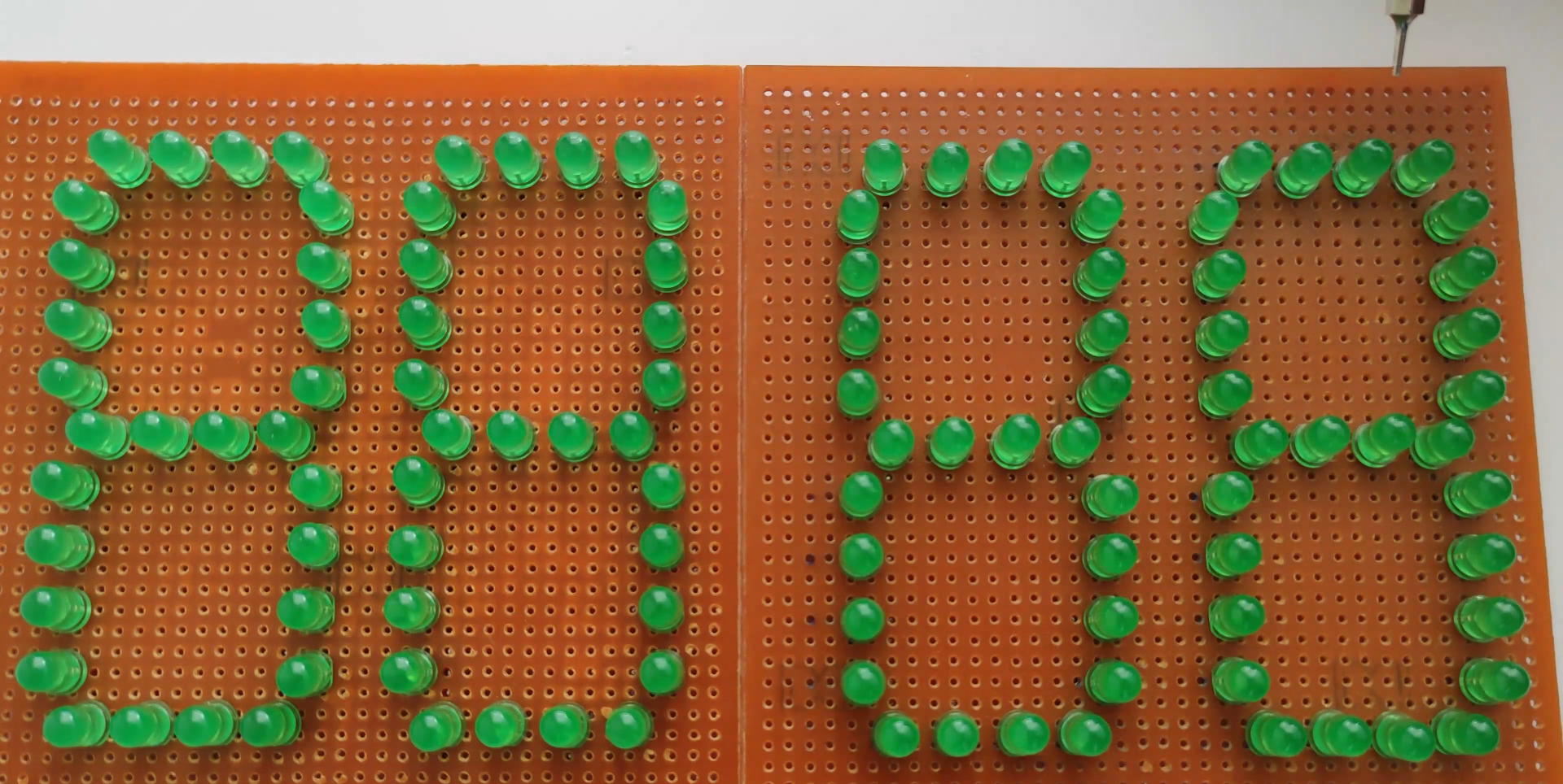
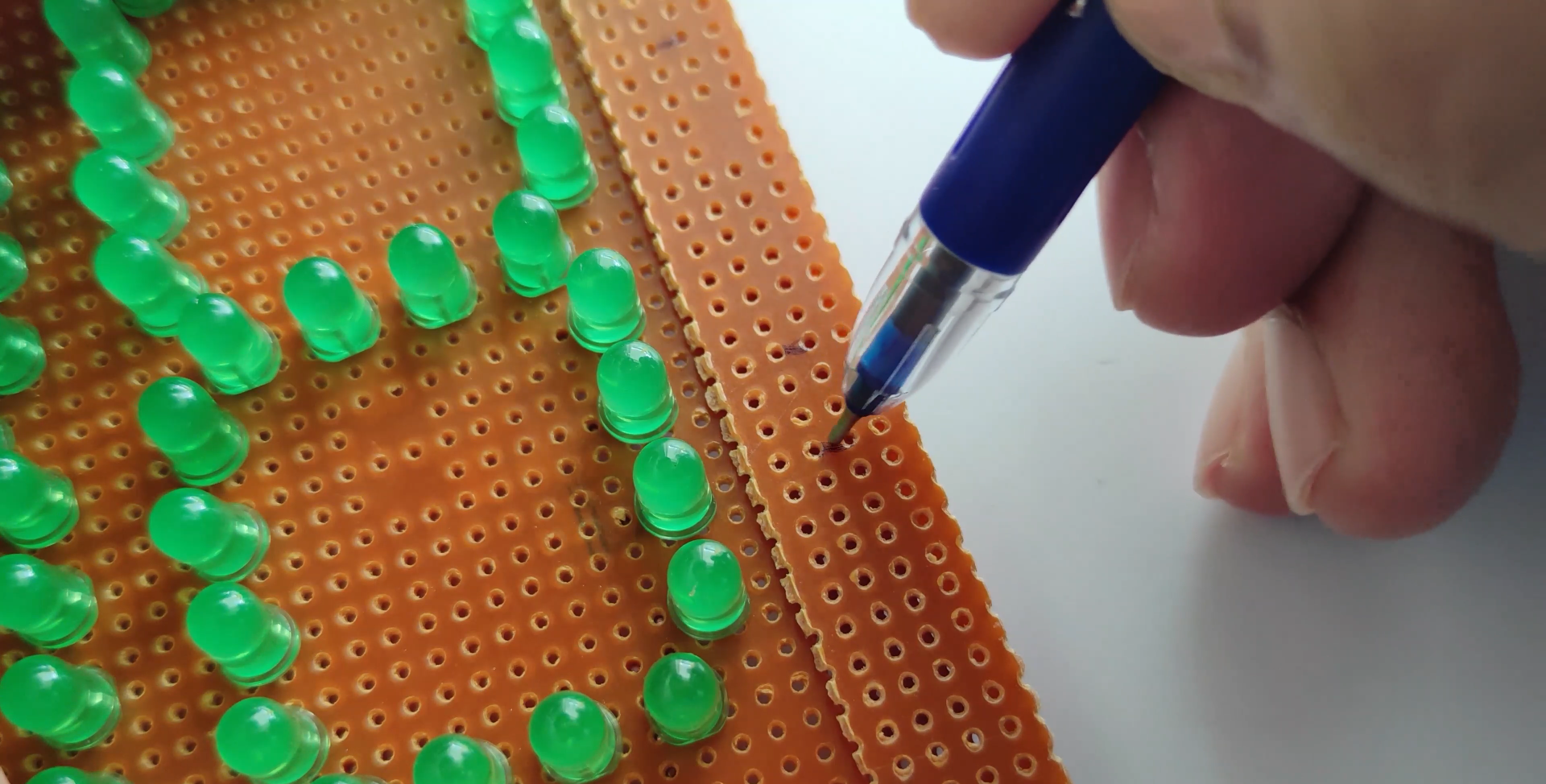
In this case, I used it to simulate an analog clock without its hands, with very interesting results. The hours and minutes are placed around the center of matrix giving a familiar look of analog clocks. The code I have developed applies a little of trigonometry (sine and cosine) to calculate the coordinates of hours and minutes to be shown into LED matrix. With that I saved many lines of coding.
Every time you reset or restart the Arduino, the time mode will change.
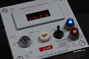
The first four digits at left of display show the hours and minutes in decimal numbers. The next three digits show the hours, minutes and seconds in binary notation and the last digit at right inform the weekday.
About the code, I had to develop a way to use the "LedControl" library to turn conventional 7-Seg decimal display into a Binary display. The solution is to use "setRow" function that is usually applied for dot matrix display.
24-hour clock display need six seven segment displays. But for building digital clock we have to use only a single microcontroller. The problem we face is the lack of input pins on the microcontroller. In Arduino UNO it contain ATMEGA328p microcontroller which has 23 input pins only. Whereas for making clock we require six displays. As one display would take 8 pins and so three SSD would take 24 pins. For making the connections we have to use multiplexing all the seven segment displays.
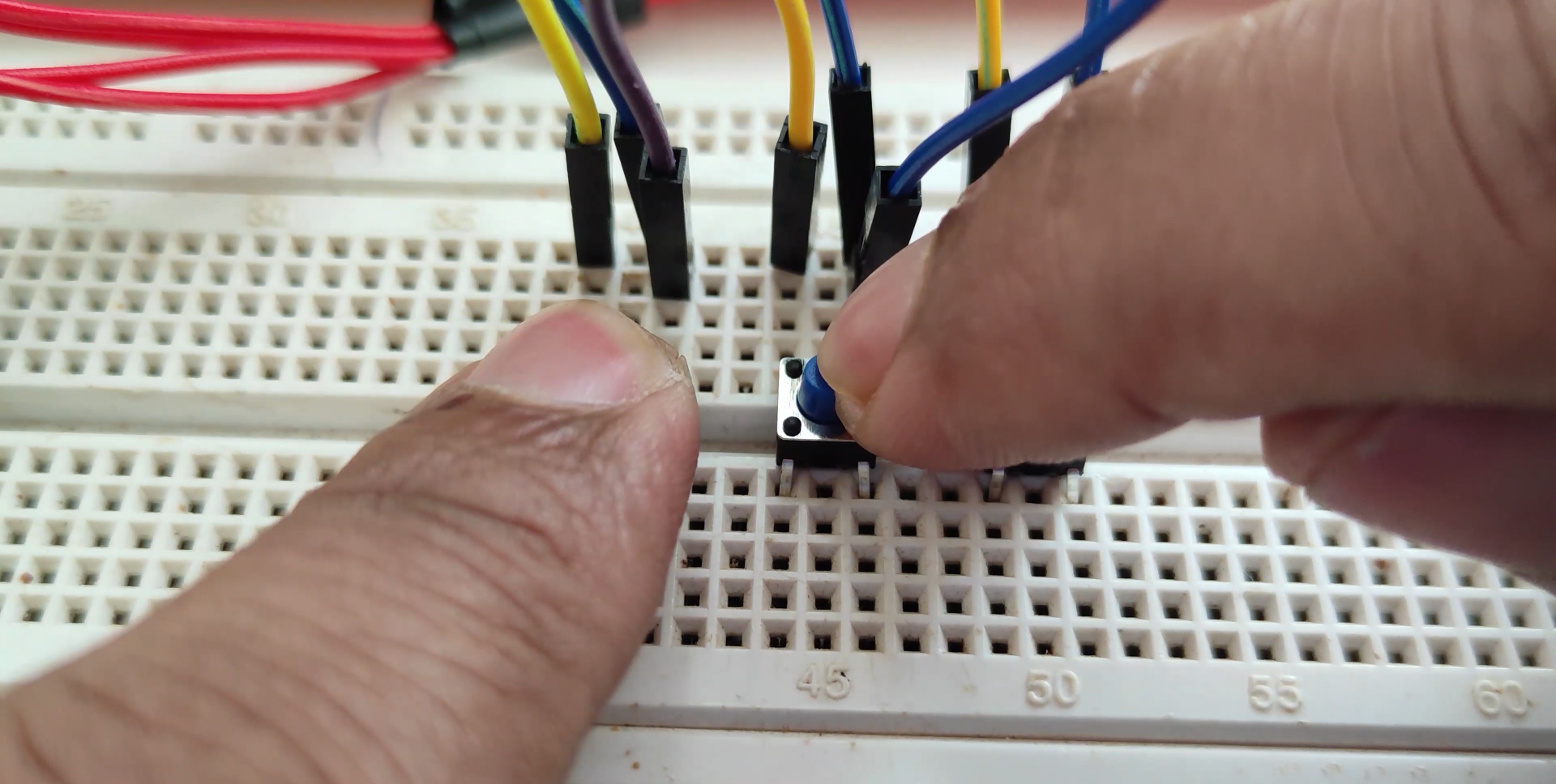
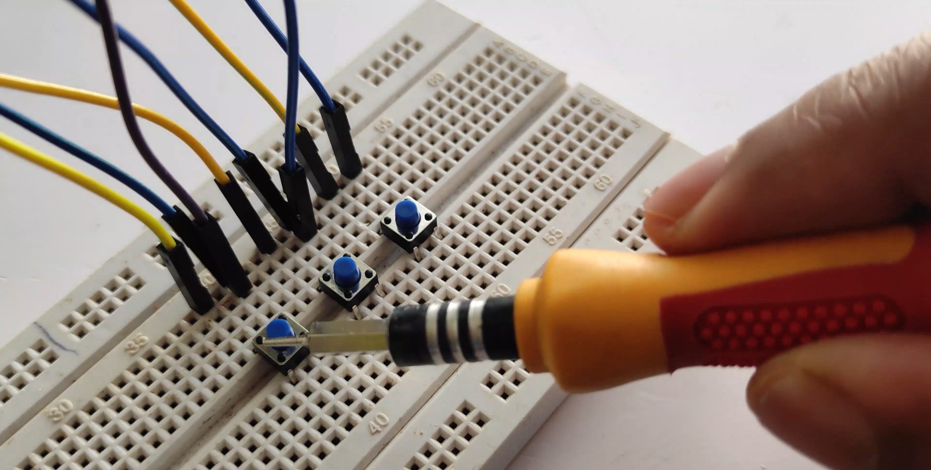
The display should be such that SU will count from 0 to 9 for every second, ST will count 0 to 5 for every 10 seconds. Similarly, MU for every 60 seconds and for MT for every 10minutes. HU should also be same as SU and MU but for every 60 minutes and MT for every 10 hours. Keep in mind when the display shows 23:59:59 it should reset to 00:00:00 and again run. For making the digital clock first we need to execute the program for a single display to run decade counter in a seven segment displays The breadboard can be divided into 5 segments. In each of the green segments the pins are internally connected so as to have the same voltage. Similarly, in the central segments the pins in each column are internally connected in the same fashion as the blue columns
In the control of display I have used an Arduino Uno R3 and 02 ICs of 74HC595 (8 bit shift register with output latches).
The use of shift register is important to save output ports of Arduino and with it is necessary only 3 outputs of Arduino to control the display.
There are two breakouts: one for the sensor of temperature (ºC - Celsius / ºF - Fahrenheit degrees) and humidity (in %) and another one for the RTC (Real Time Clock).
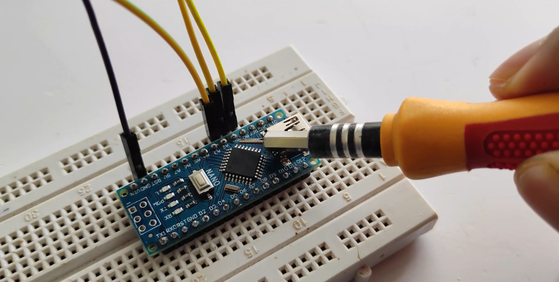
The assembly is very simple, but is necessary to pay attention with the jumpers connections.
 Patrick Hickey
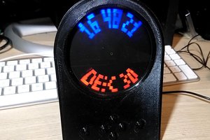
 joekutz
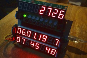
 Michael Wessel
 Alexander Stepanov