Assembly of the components is fairly straightforward, but if you don't have experience with SMT parts it could take a little while. What you will need is:
_______________________________________________
- Fine tip soldering iron (25 to 30W) or about 280°C temp. controlled tip using 60/40 rosin core solder.
- Solder braid in case you make a mistake and have to clean up.
- Optional hot air rework station, not really req'd but nice to have.
- A small piece of 320 grit wet/dry sandpaper - to clean the PCB before assembly.
- A bit of petroleum jelly (optional) - to keep the PCB from oxidizing if you work in sessions and to help the SMT parts stick.
- Fine tip tweezers for handling the SMT parts.
- Anti-static work surface or some alum. foil as a temporary surface.
- Handheld drill or drill press for the enclosure holes. Note the PDF template image.
- Mini rat tail file or (220grit) sandpaper wrapped firmly on a pencil tip to deburr the holes in the Aluminum.
________________________________________________
Additionally have a look at my SMT PCB maker project (https://hackaday.io/project/7938-pcb-smt-maker-lab-home) if you plan to make your own double sided FR4 PCB. It is how I make the PCBs as well. The EAGLECAD PCB files are in the shared folder on the sidebar under the gallery pics.
The kit-of all-parts will include the drilled and de-burred end plates and the alum. enclosure. Contact me at protofabtt@gmail.com for availability. As a convenience I can supply whatever component mix you prefer, including just the PCB or the connectors.
________________________________________________
The first component to secure is the SMA launcher.
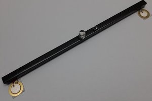
Mount it in the enclosure with just the SMA endplate and the bottom section of the enclosure assembled with two enclosure screws. Tighten the SMA nut, hand tight with the 'legs' horizontal and the centre pin oriented upward. Note the images supplied as a guide.
Slide in the PCB with the copper SMA pads pre-tinned on both sides of the PCB. You may have to file/sand the side edges of the PCB for a snug fit. Once the PCB SMA pads are aligned with the SMA launcher, solder it in place to the launcher. Now remove the bottom of the enclosure from the SMA plate and solder the two remaining ground legs of the launcher. The launcher is a 1.6mm launcher and the PCB is a 0.8mm PCB so you have a little clearance to align the fitment. Fill any gap with solder. remove the SMA nut and the PCB/launcher assembly from the end plate...now you can continue installing the SMT components.
______________________________________________
There are a couple vias which require a bit of component lead (from the chokes) to ground both sides of the copper planes. These are essential, as is soldering both layers of the rear edge mount, thru hole, choke pads to ensure a low inductance ground plane.
______________________________________________
When constructing the LEMO 304 connector end, you might need to widen the expandable gland (4 tines) thru which the cable passes, a bit of pet. jelly helps here as well as it is snug. Note the images supplied for the assembly and the color codes of the wiring. If you make a mistake here, the unit may always show unleveled on the SG 504 indicator. But no harm will come to the head or the SG-504 plugin.
The drain/shield wire needs to fold back on the cable so that the metal gland slides over it, removing some strands of the shield is usually required for the fit to be good.
_____________________________________________
I supply a BNC pigtail for use with the head, but if you prefer you can assemble a 3' RG58 or RG400 cable directly to the head to remove the need for a BNC barrel and BNC m2m patch cable to connect to the SG-504 BNC-f output. If you're using the pigtail, be careful when stripping the insulation from center core, it can pull right out of the pigtail, so grip it with a needle nose pliers to prevent that.
_______________________________________________
When assembling SMT parts with a soldering iron, the technique is to heavily...
Read more » mosaicmerc
 Anthony Kouttron
 Chris
Chris
 Lithium ION