 Eddie
EddieVideo of Tee Eye and Proof Concept
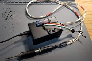
Video of my first attempt at soldering to a different calculators pads and having it work with an optocoupler and the final result of the project.
Final Thoughts:
Aside from having to buy the optocouplers I wanted to try and reuse as many other components as I could. The PCBs, LEDs, Resistors, and wires were all salvaged from different projects and random tech things people give me.
The shape and form are open to your interpretation but I wanted to play with braiding and weaving wires together as opposed to a clean and neat form. This seemed more indicative of the reborn calculator being.
Anyway thanks for checking this out and hopefully I don't get destroyed too hard in the comments.
Code Time:
The code was pretty straightforward.
- Input String
- Parse String
- Write Pin High
- The letter Appears on the calculator
Next Steps:
So now that I knew I could solder wires to the pads on the calculator it was time to figure out how to actually get input onto the screen without manually typing or shorting wires.
I had always known I wanted to use an Arduino to "press buttons". They're easy enough to use and I always have a few lying around. This particular Arduino was actually a gift from my friend @atltvhead
Transistors:
My first thought was to use transistors to short the wires but let me tell you I have no idea, even after my friend @william kennedy who is an EE explained how they work to me, how transistors work. So after a frustrating series of attempts, I decided I needed to move on until the day I can wrap my head around transistors.
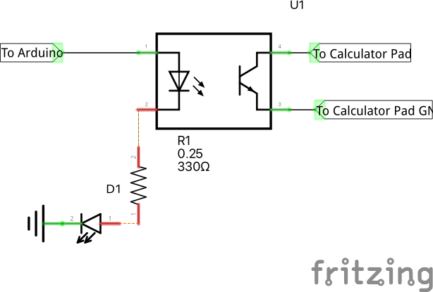
Optocoupler:
After doing some research to see what my options were I finally settled on using optocouplers!
It was a really straightforward circuit to make and it would allow me some artistic liberties in showing the button presses happening by using an LED to visualize when a pin on the Arduino had been written HIGH. It would also make visual debugging easier! Although thankfully that turned out to not be necessary.
Proof of Concept:
How do you make a calculator calculate without touching it?? This isn't the first time I've run into this problem but this is the first time I decided to actually sit down and try and figure out what to do. Fair warning I'm not an electrical engineer just someone who has always enjoyed tinkering and trying to understand so what follows is my understanding of how things work.
From my understanding, there is some conductive material on the PCB that when shorted by a conductive pad will cause something to happen. Move a character on the screen, turn on an LED, or calculate a calculator!
From measuring voltages I think that different buttons produce different voltages on the same input maybe which allows for different things to happen on the same input pin on the IC?? I'd probably need to sit around with an oscilloscope to figure that out or maybe find a data sheet for the IC. But I'm really new to both of those. All just speculation on my end.
From the number of things with buttons I've taken apart in my life, I've come across two main kinds of conductive pads. The first type is some kind of conductive metal, usually, copper/gold, and the second type is some kind of z-conductive resin (only conductive on the up/down axis) or maybe just conductive resin. Here are some pictures!
Conductive Metal Pads:


Conductive metal pads are the best because you can just solder wires onto them! Also, I know, how could you do that to a poor GameBoy pocket? Well, why not?
Some kind of conductive resin??

 David H. Bronke
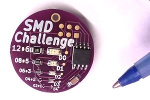
 MakersBox
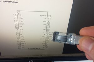
 Jorj Bauer
 mrpendent