-
fibonacci numbers and a lisp interpreter
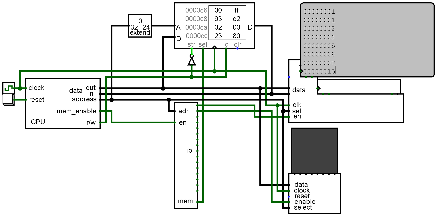
02/02/2017 at 03:22 • 0 commentsNow that risk-vee has a mostly complete assembler it is time for some non-trivial programs. First up is a little program that prints the Fibonacci sequence (in hex) to the console. (the code and an assembled image of it is in the GitHub repo)
![]()
While the compute part isn't very complicated, the routines for printing were a little more involved. Nothing groundbreaking really, but certainly across the triviality threshold.
The more interesting bit is the lisp interpreter I'm working on. I have written a few lisps, but never one in assembly. In light of that, not going for a complicated implementation is the obvious course of action. Implementation details: it is a lisp1, stop-and-copy garbage collection, deep binding, minimal data types (pair, int, id, function), no macros (yet?), no TCO, no continuations, and lexical scoping. As of right now the only thing I have done (but not really tested) is the garbage collector.
This brings us to the next point. Debugging large(ish) programs on a computer that runs at ~3khz is impossibly tedious. Waiting 10-20 seconds for your code to run up to whatever error you're looking for isn't fun. To work around this issue I'm probably going to write an emulator.
-
risk-vee-assembler (RVeA)
01/21/2017 at 18:29 • 0 commentsMost of the interesting bits of my assembler are finished. For under 500 lines of sparsely commented javascript it already has a good deal of functionality. Highlights include:
- 18 pseudoinstructions (chapter 21 in the 2.1 RISC-V spec)
- register aliases according to the standard calling convention
- data assembler directives (byte, half, word, string...)
- user defined symbolic constants
Pseudoinstructions
Currently implemented pseudoinstructions are:
- nop
- li (load immediate)
- mv (move)
- not
- neg
- seqz (set equal zero)
- snez (set not equal zero)
- sltz (set less than zero)
- sgtz (set greater than zero)
- beqz (branch if zero)
- bnez (branch not zero)
- blez (branch equal or less than zero)
- bgez (branch equal or greater than zero)
- bltz (branch less than zero)
- bgtz (branch greater than zero)
- j (unconditional jump)
- jr (jump register)
- ret (return)
Register Names
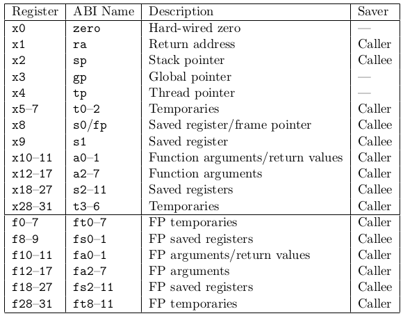
The RISC-V standard calling convention gives a name to each of the 32 GPRs. They are as follows (this is table 20.2 in the 2.1 spec document):
![]()
With the exception of the floating point registers (which risk-vee doesn't have), each name is predefined for you in RVeA. Implementing this was probably the single largest improvement I have made so far (although labels are really nice too).
Assembler Directives
RVeA supports a handful of assembler directives. They are:
- .byte
- .half
- .word
- .string (a string terminated by a null byte)
- .stringu (as above except unterminated)
- .constant (define a symbolic constant for use in your program)
If you want to tinker around with it you'll need to grab node.js and then get the assembler from the risk-vee repository. After that assembling things is just a matter of:
node assembler.js whatever.s > whatever.binNotice that you have to send the output to a file yourself. At the moment RVeA just spits the assembled code to stdout. Right now it can only generate logisim binary files, but in the future I'll add options for raw binary output and Fallout 4 compatible files.
Once you have your binary file, right click on the RAM object in logisim, click load image, select your file, and then enable ticks (ctrl-k).
At some point I'm sure I'll get a HiFive 1. Extending RVeA for compatibility would be the obvious next step at that time. The biggest issue is instruction alignment: in a "real" implementation of RISC-V every instruction has to be word-aligned. Due to how risk-vee accesses memory (serially, a byte at a time) I'm not currently enforcing that, but it should just be a matter of tying the bottom two bits of the PC to 0. Well, that plus some checks for alignment in the assembler.
If you get your hands on a HiFive before you see a post about it here it means that you have one before me. Feel free to send me a message if you'd like to play around with RVeA and I'll see what I can do.
-
Hello world!
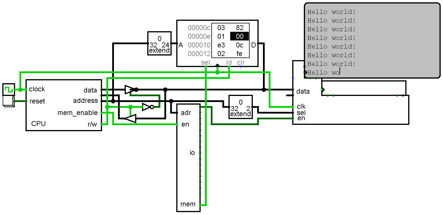
01/06/2017 at 05:29 • 0 comments![]()
There isn't a whole lot to say about it, but risk-vee now has a text console. It is located at the first I/O port (0xff000000) and has four registers: output, data available, input, and reset. Logisim can't handle bi-directional pins on subcircuits so for now the input register (data from the keyboard) isn't hooked up. I'll need to restructure the circuit a little bit to make it work, but I don't feel like playing with that right now.
My assembler isn't complete enough to handle it, but the hello world program looks like this:
lui 1, 0xff000000	// output port
addi 2, 0, 0x20		// string base
add 3, 0, 2		// index
lb 4, 3, 0		// get character
beq 4, 0, -8		// if 00, reset index
sb 1, 4, 0		// write character
addi 3, 3, 1		// increment index
beq 0, 0, -16
.string "Hello world!"
As usual, not that exciting, but now we know load upper immediate (LUI) and the load/store instructions work properly. My next task will probably be making a table of the instructions risk-vee supports, their cycle length, and whether they have been tested or not.
-
Memory-mapped I/O
12/29/2016 at 21:23 • 0 commentsWhile we only have 37 instructions (a subset of the RV32I ISA) testing each one manually is too tedious. In a more sophisticated simulation we could automate the testing (reset the processor, run an instruction or two, and then verify for proper state), but Logisim provides no means for us to do this. This means we'll do it the dumb way: instead of verifying correctness we'll assume everything works properly, write additional programs, and fix errors as they pop up.
To give us something to play with I'll be mapping some things into memory. Addresses 0xFF000000 up will be reserved for I/O and decoded into 16 1MB ports. Logisim provides tty and keyboard components which will serve the same purpose as a UART would in a physical implementation. Additionally, every good computer needs front panel switches and blinky lights so one of the ports will hold 32 of each.
I have the "what" somewhat figured out. Now it is just a matter of finding the time to tinker with the circuit.
-
An assembler! ...or, well, half of one.
12/25/2016 at 18:31 • 0 commentsI decided to (for now) forgo using the GNU toolchain for now so I can play with building my own. So far I have the output portion of an assembler done which is just enough to start writing test programs. The biggest program risk-vee has run is as follows:
addi r1, r1, 1
addi r2, r2, 5
addi r3, r3, 1
bne r2, r3, -4
sub r3, r3, r1
bne r3, r0, -4
bne r0, r1, -16
In a nutshell: count register 3 up and down between 0 and 5.
Not the most exciting thing in the world, but it did uncover a few bugs in the microcode. Branch instructions were using the wrong immediate format and comparing registers improperly (enabling a latch at the wrong time).
My desktop, which has an old i7 2700k running at 4.4ghz, was able to run the circuit at 3.8khz with a clock setting of 4.1khz in Logisim. I have a stable profile for 4.9ghz, but unless I go crazy and try to build a GPU the extra horsepower shouldn't be needed. If you play with the program above I am interested in hearing your performance numbers and your cpu+clockspeed. Right now the only two data points I have are my desktop and my little laptop which has an AMD e-350 underclocked to 800mhz (it ran slow and wouldn't even give me a simulation speed).
As usual, I uploaded a RAM image of the program above. At some point in the next few days I'm going throw everything up on github. Now that I'm actually writing code instead of designing a circuit we need version control.
-
First (trivial) test program!
12/22/2016 at 03:57 • 2 commentsaddi r1, r1, 1 add r2, r1, r1 jalr r0, r0, 0
All it does is increment r1 and set r2 to r1*2 in a loop. Told you it was trivial.
It comes out as the following for anyone wanting to poke it into memory themselves. A RAM image of it is in the project files as well.
93 80 10 00 33 81 10 00 67 00 00 00
I usually like the bit where you have to hand assemble your first few programs. Usually. It isn't so bad when you have variable length instructions, but setting the bits in a fixed length architecture is a real pain.Time to either write an assembler or get the gnu riscv toolchain set up.
-
microcode: complete but untested
12/21/2016 at 05:55 • 3 commentsI just finished the microcode image. Initially the plan was to write a prolog program that could read the instruction description pseudocode that I put together yesterday, but I ended up going with javascript instead. My prolog is really rusty and I wasn't in the mood to fight with it. Maybe next time.
Our microsequencer is 15-bits wide: 11-bits of opcode and 4-bits for the microinstructions of each instruction. This means the control store is 32kx32. In putting it together I noticed that every opcode ends with two ones. In a hardware implementation I would probably drop the bottom two bits which would shrink the control store down to 8kx32.
The control store is split up into 16 word entries. Every instruction can be up to 16 microinstructions long. The first entry takes care of fetching the next instruction and putting it into the instruction register. Each instruction ends with resetting the microsequencer by writing zeroes into the instruction register which starts the next instruction. This gives us a little quirk in the design. If we ever fetch an instruction with zeroes in the opcode bits we will hang there forever. Yup, we've got a halt & catch fire instruction.
I don't have the riscv toolchain set up, but I did manually poke an ADDI instruction into memory and it executed properly. The program that made the microcode image and a copy of said image are in the project files. If you go to play with it, right click on the control store ROM and select "load image." After that enable ticks (ctrl-k) and watch it run.
-
microcode and design mistakes
12/20/2016 at 05:03 • 0 commentsWith the circuit finished I started on the microcode tonight. The first step was to spell out each instruction as a series of microinstructions (in pseudocode). For example:
reg(rs1) -> alu_a
reg(rs2) -> alu_b
alu_o -> reg(rsd); alu_op(and)
is the AND instruction. That reads as
- Transfer the value of the register specified in the rs1 portion of the instruction to the A input of the ALU
- Do the same with rs2 and the ALU's B input
- Set the ALU operation to AND and transfer the output of the ALU to the register rsd points at
This isn't very interesting for anyone who has done any CPU design, but I'd like to do a series of posts detailing how everything works at that level of detail. Hopefully this project will be simple enough for use when explaining things to a newbie (as long as they don't look too long at the corners I'm cutting here and there).
Now that the microcode is done we can see how many cycles each instruction will take. An instruction fetch will take 6 cycles (ouch!), and the most expensive instruction (LW) takes 18 cycles including the fetch. I will give more details when I go over the memory unit, but the biggest reason that things take so long is the fact that we're doing our reads one byte at a time. Much slower than having a 32-bit external data bus, but it makes loading misaligned values much easier.
What was the mistake that the title mentions? The LH and LB instructions sign-extend the value loaded from memory and I completely overlooked that when I did the memory unit. Luckily we had some free spots in the ALU for an extend halfword and extend byte operation. That will work well enough for now, but if I ever go to actually build risk-vee in hardware I will look at doing that in the memory unit itself.
Up next is writing a program to generate the microcode ROM.