 mit41301
Intended use:
RDA Microelectronics make RDA7088N is a simple FM Tuner with stereo output. As per datasheet we need not to have a host to program this FM Tuner IC. Just connecting 5 tactile switchs we can make a standalone FM radio receiver. The audio output from the IC is capable of driving pair of 32 ohms speaker. The tuner supports 76-108MHz band. We can generate RCLK using a standard 32.768kHz crystal and have inbuilt AGC feature.
The pinout of RDA7088 IC is as below
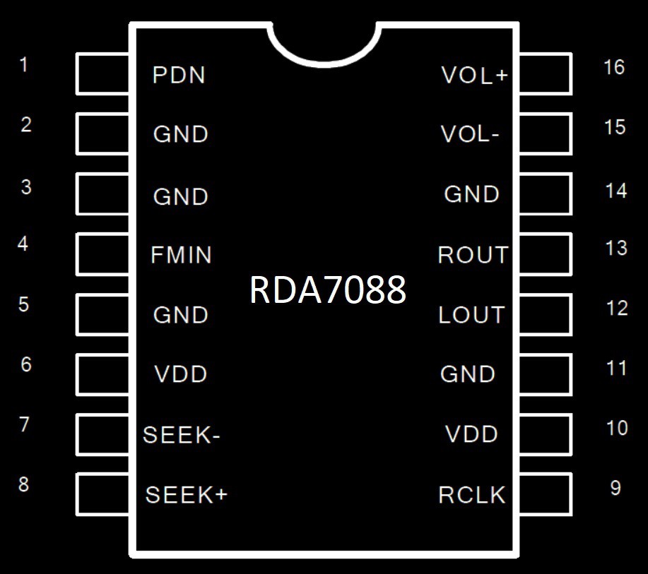
We can control power ON/OFF (PDN-1), Channel seek+(#8) /seek-(#7) and Volume using VOL+(#16)/VOL-(#15). The tuner's internal operation is controlled by a tiny FSM(Finite State Machine) inside the IC.
Basic application circuit is as below
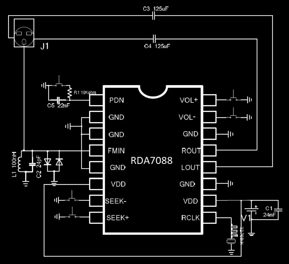
Tested few RDA7088N ICs with breadboard along with DIP to SOP16 adapter. Everything works as per datasheet. FM tuner IC directly drives the 32 ohms headphone directly.
HACKED VERSION:
As per the RDA7088N pinout there are two VDD pins (6 and 10). Pin#10 is the actual VDD and Pin#6 is nothing to do with VDD. If you connect the RDA7088 IC pin#6 to VDD then the FSM is active and you can control the IC with tactile switches connected to pin# 1,7,8,15&16.
If you connect the RDA7088 IC pin#6 to GND then the IC will function as a I2C controlled stereo receiver with RDS and I2S features!!!
I²C INTERFACE!
When we connect the RDA7088 pin 6 to GND, then the FSM is disabled and I2C bus will be active. Now we can control the RDA7088 using standard I2C bus along with RDA family programming specifications.
Tested with PIC10F200 in SOT23-6 and DIP-8. It worked well with I2C bus. Since PIC10F200 is having only 4 I/O pins , added IR infrared remote control so that we can add many functions in future by just using only one input pin. Since GP3 is input only pin it is decided to use that pin for IR remote control input. After successful implementation on PIC10F200 with I2C protocol with IR remote control, little curious to explore the I2S feature of the RDA7088 IC. Looking through RDA FM tuner family datasheets and after doing some simple tests using PIC10F200, able to implement the I2S output from RDA7088 with IR remote control.
There are many Arduino sktches available for FM Tuner using RDA5807M, TEA5767, Si4703 or AR1010 etc., for easy testing through I2C bus.
The pinout of RDA family FM tuner available in SOP16 is as below picture.
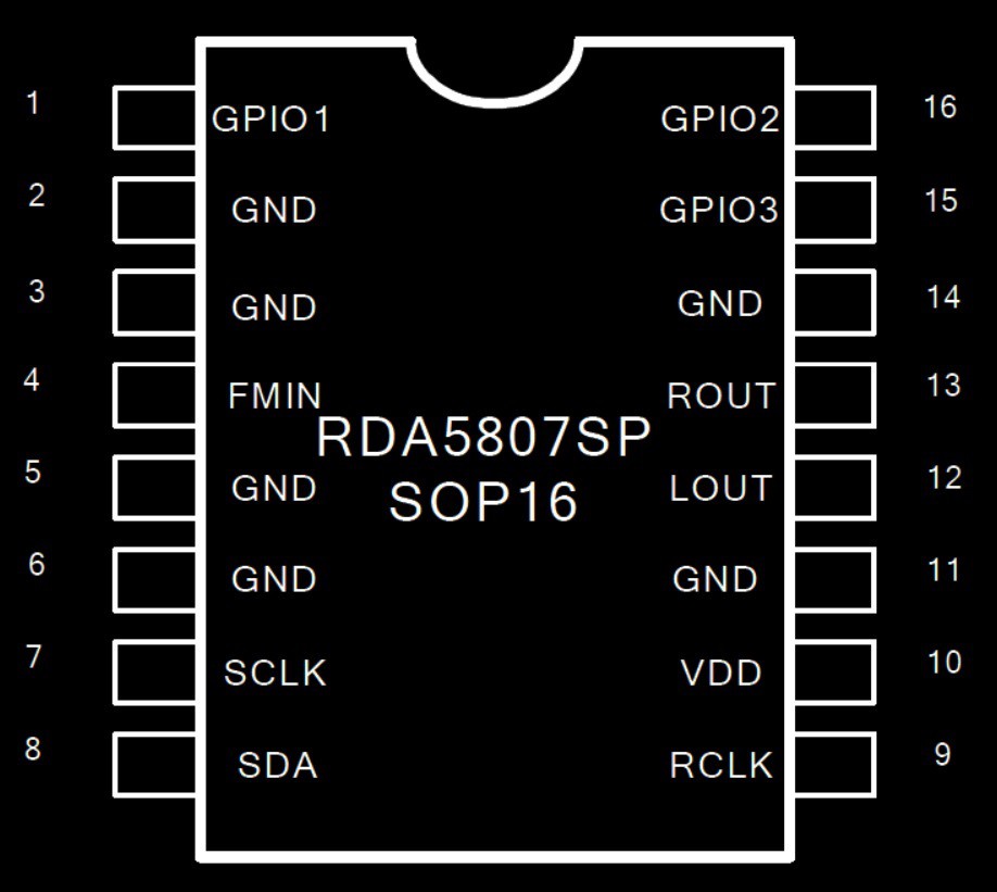
Pin 7(SCLK) and pin 8(SDA) are used for I2C communication. There are three GPIO available for user.
Basic application circuit using I2C is as below from the datasheet.
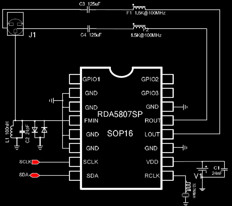
The three GPIOs are available for user and can be set or reset by writing into specific registers. But once we enable the I2S then these pins can no longer used as GPIOs and start emitting the I2S through these GPIO pins.
The basic I2S digital audio format as per RDA datasheet is as follows
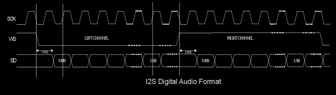
The I2S bus has three lines:
• continuous serial clock (SCK)
• word select (WS)
• serial data (SD)
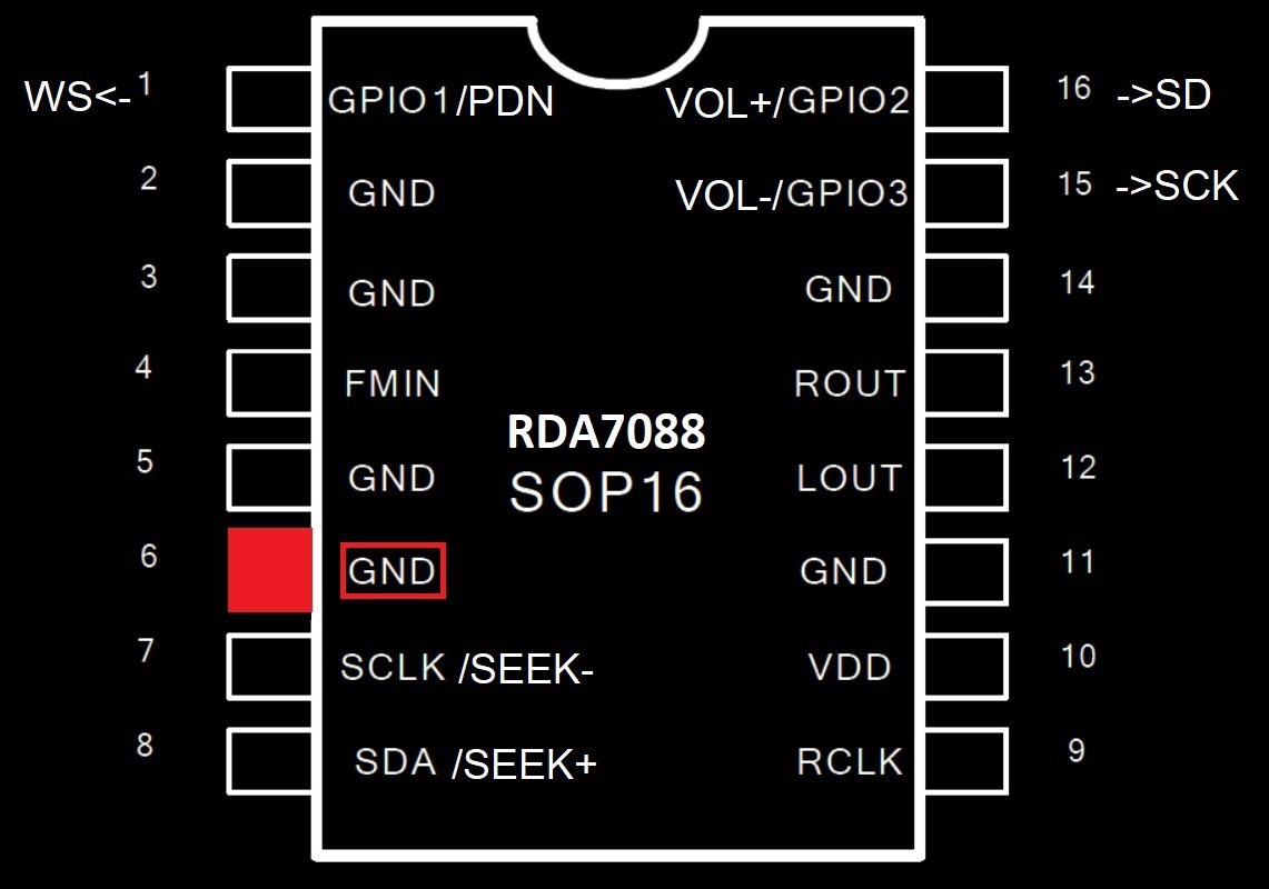
Instead of connecting the pin#6 to VDD, if we connect pin#6 to GND, then the RDA7088 can behave as I²C controlled FM Tuner with RDS and I²S output capable. The above picture gives a idea or feeling how the pins and functions of RDA7088 changes when we connect pin#6 to GND instead of VDD.
I²S OUTPUT:
To enable the I²S output, there are just 3 bits needs to be set
REGister 04H bit#6 I2S_ENABLE - 1

By default this bit is "0". We should enable this bit to "1" for enabling the I²S output.
REGister 06H bit#9 data_signed = "1"
REGister 06H bits[7:4] I2S_SW_CNT[4:0] - 4'b1000 for 48kbps
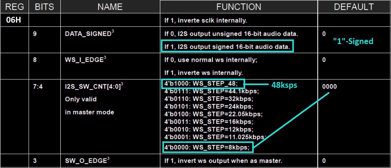
Most of the I²S audio DACs tested supported the signed audio data. Default DATA_SIGNED bit is "0" for unsigned 16-bit audio data. We should enable DATA_SIGNED = "1" for signed 16-bit audio data.
Default audio sampling rate is 8kbps(8ksps or 8kHz). We can select 44.1kHz or 48kHz sampling rate for better audio quality of I²S output. Please refer to the above table for bits [7..4] of the REG 06H
These bits can be set during initialization once.
The FM Tuner operates on 3.3V DC source. Any controller with 3.3V logic level O/P can be directly interfaced through the I²C bus for controlling the FM Tuner. Any higher voltage (e.g 5V) devices should use the logic level shifter for safe and reliable I²C communication. FM tuner having internal pullup resistors for I²C. We can add additional external pullup if necessary.
SOFTWARE
The challenge with developing software using PIC10F200 is the available hardware and memory resources. Below table shows the available resources.
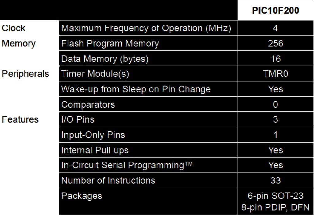
PIC10F200 is having 3 I/O pins and 1 dedicated Input pin. The internal Data Memory is just 16 bytes. We can write maximum 255 assembly instructions(256*12bit=384bytes). The instruction set consists of only simple 33 instructions.
There is an excellent tutorial on PIC10F200 available with much details and projects. The source code is based on part 15 and part 19 of the tutorial. Merging the I2C routine and IR remote code of part 15 & part 19 and still code size should not exceed 255 instructions is the challenge. We have to loose some features to accomodate the code. During initialization we have to initialize and set the bit#6 of REG 04H to "1" and Bit#9 and Bit#7 of REG 06H to "1" for I2S output.
The assembly language code for PIC10F200 using sequential access address of I2C bus(0x20)
START_RADIO:              ;Start FM radio
    CALL   I2C_START      ;Issue I2C Start condition
    MOVLW  0x20           ;Radio chip address for sequential writing is 0x20
    CALL   I2C_WRITE_BYTE ;Write the radio address via i2C
;-----------------------------------------------------------------------------
;          REG 02H - II
;-----------------------------------------------------------------------------
    MOVLW  0xD0           ;Write high byte into radio register 0x02/BASS BOOST
    CALL   I2C_WRITE_BYTE
    MOVLW  0x01           ;Write  low byte into radio register 0x02
    CALL   I2C_WRITE_BYTE
;-----------------------------------------------------------------------------
;          REG 03H - III
;-----------------------------------------------------------------------------
    MOVF   frequency_h, W ;Write high byte into radio register 0x03
    CALL   I2C_WRITE_BYTE
    MOVF   frequency_l, W ;Write  low byte into radio register 0x03
    CALL   I2C_WRITE_BYTE
;-----------------------------------------------------------------------------
;          REG 04H - IV
;-----------------------------------------------------------------------------
    MOVLW  b'00000010'    ;LOAD W Reg with 0x04 Register High byte
    CALL   I2C_WRITE_BYTE ;Write high byte into radio register 0x04
    MOVLW  b'01000000'    ;LOAD W Reg with 0x04 Register Low byte
    CALL   I2C_WRITE_BYTE ;Write high byte into radio register 0x04
;-----------------------------------------------------------------------------
;          REG 05H - V
;-----------------------------------------------------------------------------
    MOVLW  b'00000000'    ;Write high byte into radio register 0x05
    CALL   I2C_WRITE_BYTE
    MOVLW  b'00000000'    ;Write low byte into radio register 0x05
    CALL   I2C_WRITE_BYTE
;-----------------------------------------------------------------------------
;          REG 06H - VI
;-----------------------------------------------------------------------------
    MOVLW  b'00000010'    ;Write high byte into radio register 0x06
    CALL   I2C_WRITE_BYTE
    MOVLW  b'01110000'    ;Write low byte into radio register 0x06
    CALL   I2C_WRITE_BYTE
;-----------------------------------------------------------------------------
    CALL   I2C_STOP       ;Issue I2C Stop condition
;=============================================================================
The default channel frequency and default volume will be initialized later in the code. Please refer to the RDA5807 family FM Tuner datasheet and part 15 of the tutorial for more details regarding I²C address for sequential or random access.
Please read and understand tutorial part 19 for NEC IR Remote control protocol and how to findout the codes for specific remote control transmitter key. The radio uses the SEEK function for SEEK UP and SEEK DOWN through the FM BAND.
The source code is written in assembly and compiled using MPLAB IDE 8.92 and not with with MPLABX due to some practical limitations. MPLAB IDE 8.92 is still available for download from Microchip site.
PIC10F200 port assignments as below:
;#############################################################
SCL     EQU    GP1    ;SCL pin of the I²C Bus
SDA     EQU    GP2    ;SDA pin of the I²C Bus
IRx     EQU    GP3    ;INPUT ONLY PIN(IR Rx 38kHz)
;#############################################################
Only 3 pins are used and general purpose GP0 is available for future expansion.
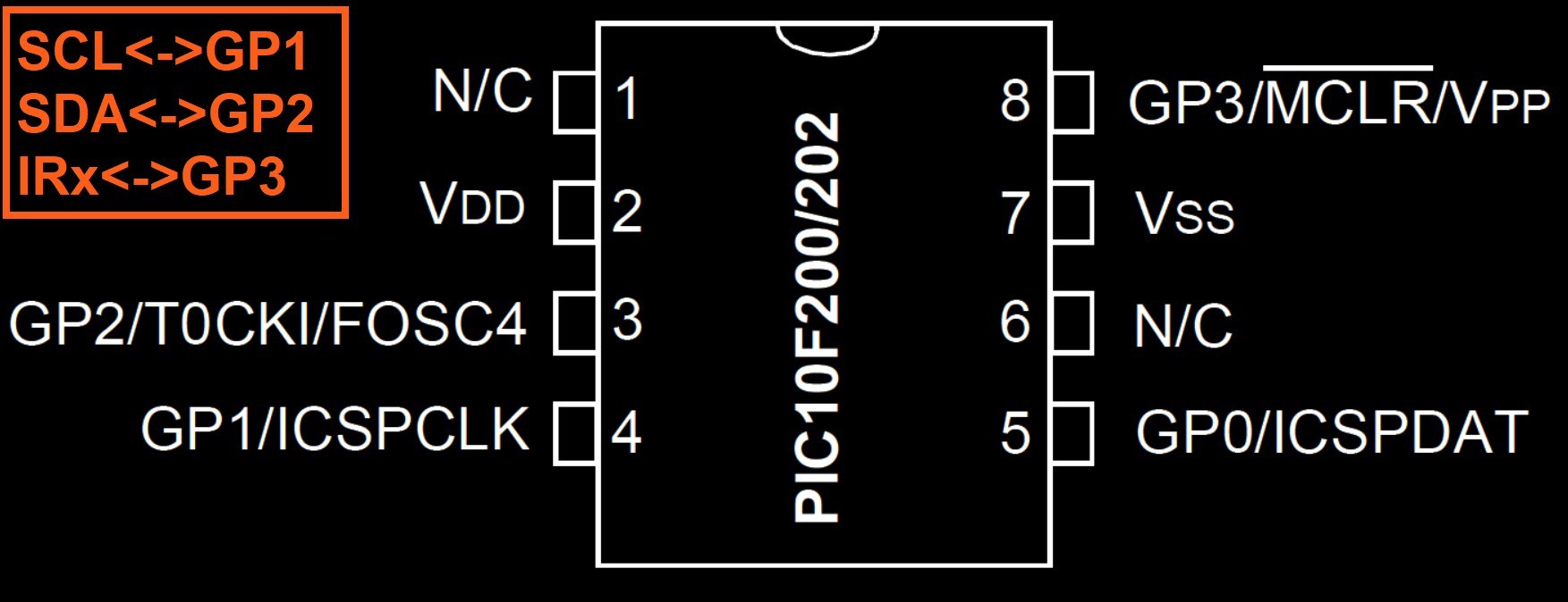
PIC10F200 DIP-8 pin assignments as above

PIC10F200 SOT-23-6 pin assignments as above
I²S DAC & AMPLIFIER
There are many off-the-shelf I²S DAC available .
Testing with the following I²S DAC devices were done.
I²S 3W Class D Amplifier Breakout - MAX98357A
I²S Stereo Decoder - UDA1334A Breakout
PCM5100A stereo DAC + PAM8908JER stereo headphone amp
PCM5102A
CS4344 D/A Conversion Module(Not tested)