Subhajit
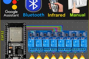
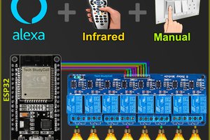
In this IoT project, I have shown how to make an IoT-based ESP32 Alexa Home Automation system to control 1 Fan and 4 home appliances with the Amazon Alexa, IR remote. Bluetooth and manual switches.
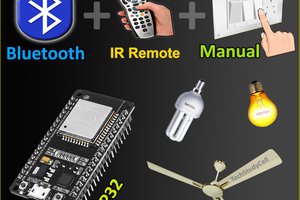
If the internet is not available, then you can control the home appliances and fan speed from IR remote. Bluetooth and manual switches. During the article, I have shown all the steps to make this home automation system.
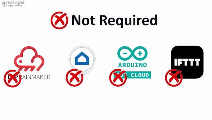
You don't need any third-party IoT applications to make this IoT project, you just need an echo device and ESP32.
During the article, I have shown all the steps to make this ESP32 home automation system.
Tutorial Video on IoT Project using ESP32 & Alexa
This Alexa ESP32 control smart relay has the following features:
- Control home appliances and fan speed with voice commands and Amazon Alexa App.
- Control ceiling fan speed and appliances with Bluetooth, IR Remote, & selector switch.
- Monitor real-time feedback in the Amazon Alexa App
- Control appliances, and fan speed without WiFi using Bluetooth App, IR Remote, & switches.
- No third-party IoT applications are required.
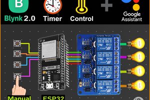
So, you can easily make this home automation project at home just by using an ESP32 and relay module. Or you can also use a custom-designed PCB for this project.
Required components for the ESP32 Project

Required components (Without PCB):
- ESP32 DevKIT V1
- 8-channel 5V SPDT Relay Module
- HC-05 Bluetooth module.
- TSOP1838 IR Receiver (with metallic case)
- Switches
- Any IR Remote
- 4-step Fan Regulator OR (2.2uf & 3.3uf 250V Capacitor, 2.2-ohm 1/2W Resistors, 220k 1/4W Resistors, and 4-step selector switch)
- Amazon Echo Dot
Required components (for PCB):
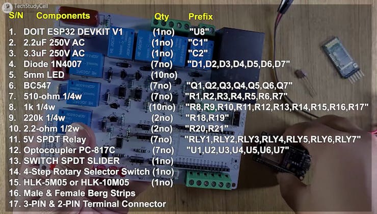
- 1. DOIT ESP32 DEVKIT V1 (1no) "U8"
- 2. 2.2uF 250V AC (1no) "C1"
- 3. 3.3uF 250V AC (1no) "C2"
- 4. Diode 1N4007 (7no) "D1, D2, D3, D4, D5, D6, D7"
- 5. 5mm LED (10no)
- 6. BC547 (7no) "Q1, Q2, Q3, Q4, Q5, Q6, Q7"
- 7. 510-ohm 1/4w (7no) "R1, R2, R3, R4, R5, R6, R7"
- 8. 1k 1/4w (10no) "R8, R9, R10, R11, R12, R13, R14, R15, R16, R17"
- 9. 220k 1/4w (2no) "R18, R19"
- 10. 2.2-ohm 1/2w (2no) "R20, R21"
- 11. 5V SPDT Relay (7no) "RLY1, RLY2, RLY3, RLY4, RLY5, RLY6, RLY7"
- 12. Optocoupler PC-817C (7no) "U1, U2, U3, U4, U5, U6, U7"
- 13. SWITCH SPDT SLIDER (1no)
- 14. 4-Step Rotary Selector Switch (1no)
- 15. HLK-5M05 or HLK-10M05 (1no)
- 16. Male & Female Berg Strips
- 17. 3-PIN & 2-PIN Terminal Connector
- 18. HC-05 Bluetooth module.
- 19. TSOP1838 IR Receiver (with metallic case)
- 20. Amazon Echo Dot
So, you can easily make this home automation project at home just by using an ESP32, HC-05, and relay module.
Or you can also use a custom-designed PCB for this project.
Circuit Diagram of the ESP32 Project
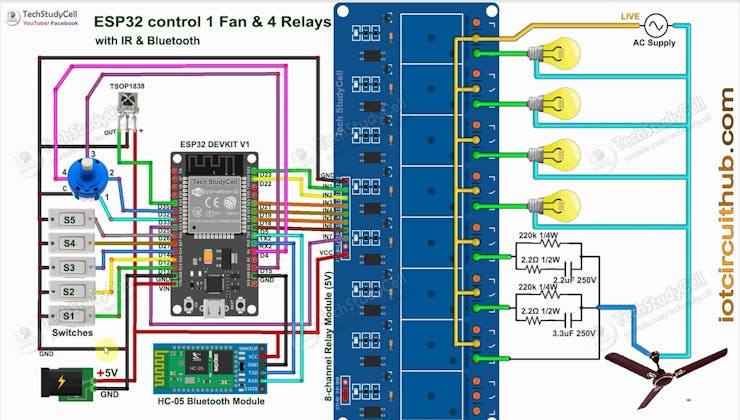
The circuit is very simple, I have used the GPIO pins D23, D22, D21 & D19 to control the 4 relays.
And the GPIO pins D13, D12, D14 & D27 are connected with switches, and GPIO D33, D32, D15 & D4 are connected with a 4-step selector switch to control the relays manually.
I used the INPUT_PULLUP function in Arduino IDE instead of the pull-up resistors.
IR remote receiver (TSOP1838) connected with D35.
The TX pin of the Bluetooth or BLE module is connected to the RX2 (GPIO16) pin of ESP32 for serial communication.
I have used a 5V mobile charger to supply the smart relay module.
Please take proper safety precautions while working with high voltage.
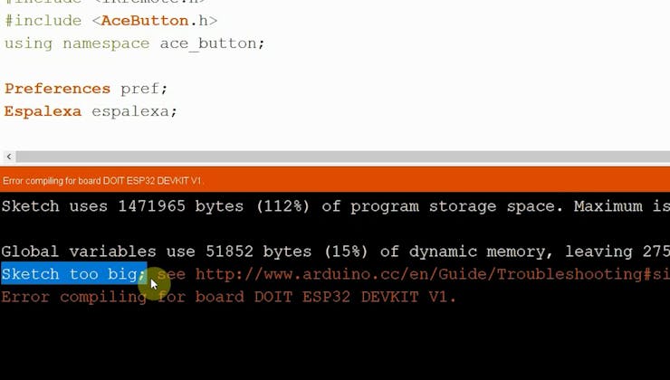
**I have not used the inbuilt Bluetooth of the ESP32, as the total size of the sketch is bigger than the ESP32 flash memory.
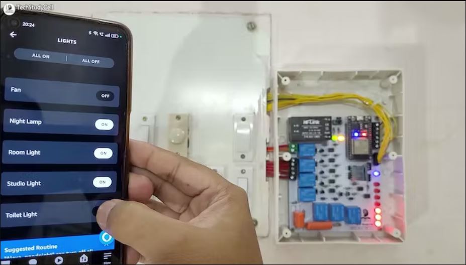
Testing the Circuit Before Designing the PCB

Before designing the PCB, I made the complete circuit using ESP32, an 8-channel relay module, HC-05, and manual switches.
As you can see, the relay can be controlled from the manual switches and Amazon Alexa App.
In the following steps, I have explained the complete projects in...
Read more »