 zpekic
In order to thoroughly test the EMZ1001A implementation, and to make a fun, demo-able system that is "doing something", a small "computer" has been created on the FPGA board, with various components supporting the microcontroller operation.
Basic features are:
- Execution of 2 pre-loaded programs ("Hello World" from internal memory and "Fibonacci" from external) - selectable by switch
- Output on 4-digit 7-segment LED (multiplexed using A[ddress] and D[ata] lines)
- Output of 8-bit ASCII (D[ata] lines, strobed with /EXT), these characters are simultaneously output to:
- 640*480 VGA which contains a 32*32 text screen (for "teletype" output) and 16*16 window to display debug info
- UART, which connected to PMOD USB allows host computer to receive output
- RUN/STOP, single step mode
- CPU clock selection from single step to 6.25MHz in 8 steps
- Baudrate selection from 600 to 57600 bps in 8 steps
- Debug info on VGA screen visualized 64 nibbles of RAM and other most important CPU registers
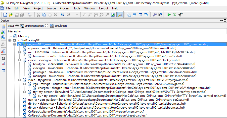
The system components are coded in sys_emz1001.vhd which is also the top level source file of the design:
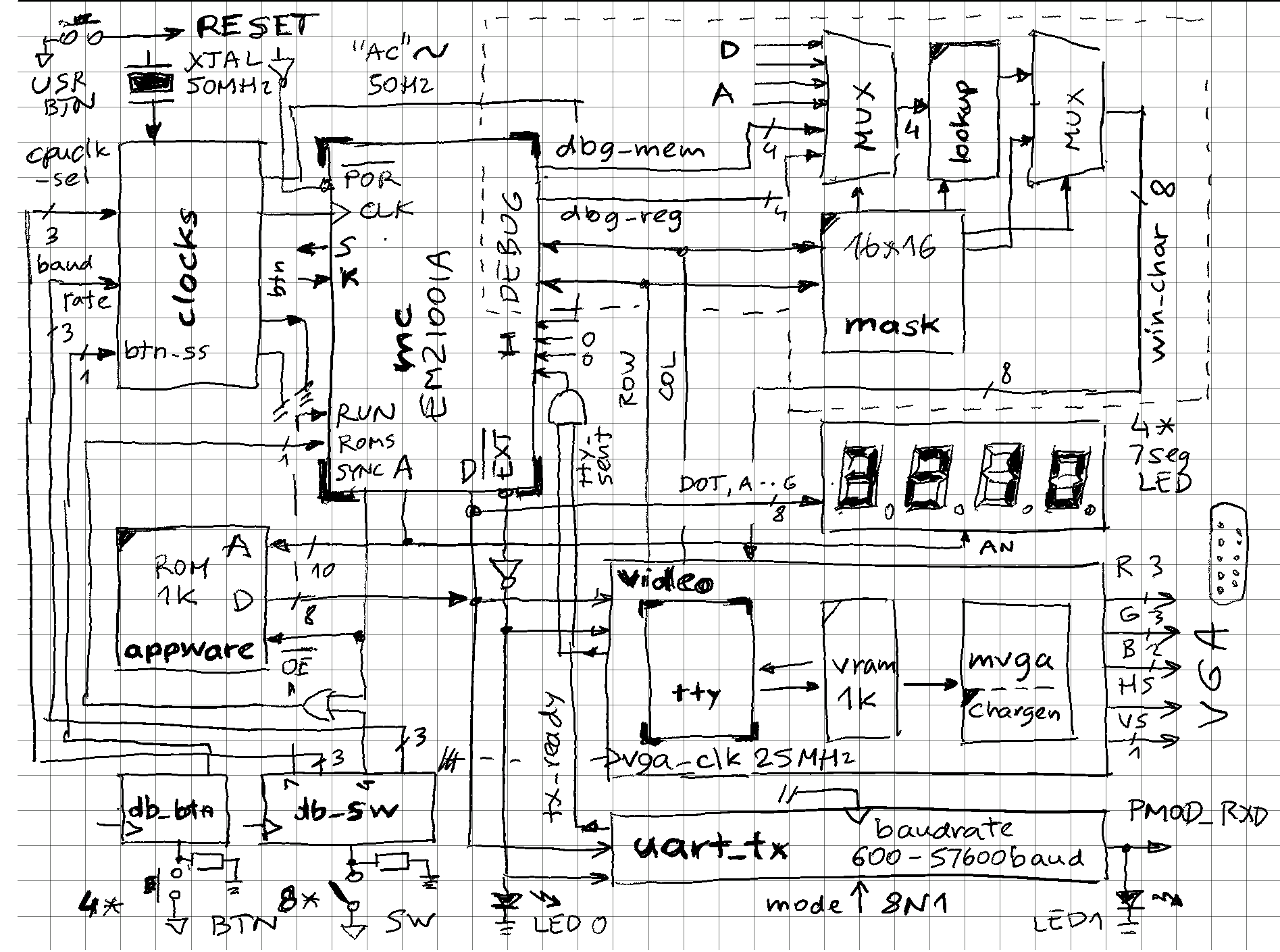
Somewhat simplified schema of main components (bolded names can be found in the code):
RESET
Mercury board has a USR_BTN which can be conveniently used as master reset. This is a positive logic signal, and is used as such by most components, except by the mc which has a negative active /POR (power on reset) signal.
clocks
Unlike many microcomputer designs which can get away with few clocks (e.g. classic Z80 with 4MHz XTAL and a 74LS04s to create a workable oscillator) this one uses many, all derived from internal Mercury FPGA 50MHz clock signal and generated by the clockgen.vhd component. Main are:
- 25MHz vga_clk - used as VGA dot clock
- cpu_clk which can go from single step (4 presses on BTN0 goes through T1, T3, T5, T7 phases of machine cycle)
- baudrate (600 - 57600 bps) - for UART
- 50Hz - simulate frequency of mains AC to be consumed by SOS instruction to time 1s intervals
- debounce_clk - drives the debouncers for switches and buttons
db_btn, db_sw
12 debouncers are programmatically generated during build time and hooked up to 8 switches and 4 buttons on Mercury baseboard. The debouncer.vhd is a glorified 8-bit shift register clocked by debounce_clk which "votes" the output based if all stages are in same state, and if not, keeps existing state. It is a very simple digital signal filter.
-- Switches on baseboard
-- SW(0) -- BAUDRATE SEL 0
-- SW(1) -- BAUDRATE SEL 1
-- SW(2) -- BAUDRATE SEL 2
-- SW(3) -- OFF: EXTERNAL ROM, ON: INTERNAL ROM
-- SW(4) -- CPUCLK SEL 0
-- SW(5) -- CPUCLK SEL 1
-- SW(6) -- CPUCLK SEL 2
-- SW(7) -- OFF: STOP, ON: RUN

SW: in std_logic_vector(7 downto 0);

-- Push buttons on baseboard
-- BTN0 - single step (effective if SW(6 downto 4)) = "000"
-- BTN1 - not used
-- BTN2 - not used
-- BTN3 - not used

BTN: in std_logic_vector(3 downto 0);
For example:
All switches off: 600 baud, external ROM (Fibonacci), CPU single step (using BTN0), stopped
All switches on: 57600 baud, internal ROM (Hello World), 6.25MHz CPU, running
appware
Simple 1k*8 ROM is mapped as lowest 1k out of 8 possible banks as "external ROM" and is holding the Fibonacci code. Same rom1k.vhd component is also used to define the "internal ROM" which lives inside the EMZ1001A, also in the first 1k memory bank.
Contents of ROM is initialized during build time, by loading the Intel .HEX file produced by microcode compiler (see "recreating a simple assembler"). This is done by invoking a function which returns a byte array of 1024 elements, defined in the emz1001_package.vhd file.
uart_tx
This is the "parallel to serial" half of a full UART - I use it often in projects to transmit to host PC, using USB to PMOD connector. It is hard-coded to 8 bits, 1 stop, no parity, but the baudrate can be selected using switches 2, 1, 0. Implementation-wise, it is a glorified 16 to 1 MUX. It also generated "ready" signal (low when transmit is in progress) which is fed to EMZ1001A input pin (I0) to check if it is ok to transmit next character.
video
Allows display of output ASCII stream and debug data (CPU internals) onto a text based VGA (640*480 == 80*60 characters). It is an aggregate of following components:
- tty_screen - a micro-coded component that accepts a stream of ASCII characters, and puts them into a video memory of a certain max width and height (32*32 in this case). It supports limited control characters such as CLS, HOME, CR, LF, and will scroll the screen if it hits the last row. For that is actually needs write access to video RAM, not just read (scroll origin register might be better implementation). Microcode can be seen here, rest of the files in this folder contain the standard microcode control unit, mapper and microcode memory and the main component integrating it together. Writing a character to video memory, incrementing cursor position, or scrolling take time so ready signal is generated and used in same way like the one from uart_tx (EMZ1001A program "blocks" until both output paths are ready for next character)
- vram - To save memory (design was getting close to what FPGA was able to contain), only 1k video RAM is used, in 32*32 configuration. It is used alternatively by tty_screen (when outside of visible VSYNC area), or VGA (when in visible area)
- vga - this is a simple, single format (60Hz, 640*480) only VGA controller. On one side it produces usual VGA signals for the monitor, and on the other row and column of the character being displayed. From this, the video RAM address can be calculated, for example A = (80 * row) + column, in case of 80*60, but here for 32*32 a simple concatenation of row & col will yield a 10-bit video RAM address. ASCII code retrieved from video RAM is used as a lookup into a character generator ROM. A single pixel is output from character generator based on the lowest 3 bits of vertical line number and lowest 3 bits of horizontal pixel position. Only 128 character definitions are stored (ROM size is halved to 1k) because bit 7 is used as "inverse".
mask
VGA controller generates character rows and columns - when these are within certain limits (see lines 390+) VGA input character no longer comes from video RAM, but from external source which is defined by the mask. Mask is 16*16, so first the offset into the mask is determined (from 0, 0 to 15, 15) and character code at that location is read. If is it printable ASCII code (32-128), then it is used directly, but if in range of 0-31, it is interpreted as driving a series of multiplexors that will select a 4-bit data from variety of sources (e.g. CPU memory or registers), convert 4-bit to ASCII character using 2 possible lookup tables, and feed that character to VGA. The end result is a "hardware window" of 16*16 size, "floating" above the rest of screen. Bit 7 (MSB) in the mask character is interpreted as "inverse" so it bypasses the MUXs and lookups and directly goes to VGA (see chargen explanation above)
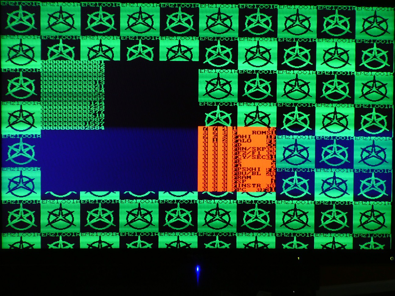
(state of CPU stopped after generating 17th Fibonacci number displayed on VGA)
mc
Finally, the microcontroller! Internals are explained elsewhere, for the system purpose it is interesting to see its connections:
- CLK - comes from the clocks component which allows speed to be varied from 0 to dizzying 6.25MHz (originals worked only up to 250kHz or so)
- nPOR - reset is low active, so inverse of system RESET tied to USR_BTN
- RUN - tied to switch 7 which allows CPU to be stopped / started at flip of a switch
- ROMS - controlled by switch 4 which either pulls it up 1, or feeds back SYNC output. In first case CPU operation mode will be 11 (internal ROM only) and in second 01 (external ROM only). Given that these 2 ROMs contain the 2 different "demo" programs, they can be selected to run at flip of switch too.
- KREF - not used, in real device this is an analog input which is one side of 4 voltage comparator, the others are tied to 4 K inputs individually. Capacitor keyboards or even simple A/D converter can be implemented this way.
- I - 4 bit input bus has MSB connected to 50Hz signal (allows SOS instruction to measure 1 second intervals), and LSB to OR of two output devices (tty and uart) ready signals, so CPU can check if they are ready for next character
- nEXTERNAL - inverted and fed into two output devices to indicate they should load ASCII character present on D bus for output. OUT instruction puts combined M and A values to D bus and generates this signal. So single OUT sends both to VGA and UART at the same time.
- SYNC - used to drive ROMS, but also the 7-segment LED display. If using external ROM, address appearing on A lines during SYNC low would lit up random digits, so LED is blanked in that mode. If internal ROM is used, A is never multiplexed between address and slave output register, so no blanking is needed. That's why in internal ROM mode LED is a bit brighter :-)
- STATUS - not used, although data appearing on this output is correct per EMZ datasheets.
- A - either a 13 bit ROM address (if external ROM mode), or 13 bits coming from output slave register, updated using PSH, PSL, MVS instructions. In this case it a "one hot bit" to select single LED to light up (common cathode or anode). So theoretically 13-digit LEDs and 52-key keyboards (13 * 4 matrix) could be driven by a modest EMZ! In this design, lowest 4 A lines drive the anodes of the 4-digit LED display
- D - either 8-bit instruction from external ROM (in external mode, when SYNC is low, EMZ puts D in tri-state mode to allow ROM to drive it), or 8-bit input/output. In this design, only output data mode is used:
- OUT instruction - nEXTERNAL is generated, data is ASCII code to be output to VGA and TTY
- DISN instruction - internal 4-bit nibble to 7-seg pattern lookup table is used to drive 7-seg cathodes (decimal point comes directly from state of Carry flag) - nEXTERNAL is not generated, so random data won't get accidentally output to TTY and VGA
- DISB instruction - random 7-seg pattern from M and A (this is the way "text" can be displayed on 7-seg display). nEXTERNAL is not generated.
(banks 0 and 1 of internal RAM contain bit patterns to used by DISB to show "letters" on 7-seg display
LED_SPACE:    .alias 0b00000000;    // LED segment patterns
LED_H:        .alias 0b00110111;    // H
LED_E:        .alias 0b01001111;    // E
LED_L:        .alias 0b00001110;    // L
LED_O:        .alias 0b00011101;    // o
LED_W:        .alias 0b00111111;    // close enough
LED_R:        .alias 0b00000101;    // r
LED_D:        .alias 0b00111101;    // d
LED_EXCL:    .alias 0b10110000;    // ! (note decimal point is on)
OUT_READY:    .alias 1;            // mask for I inputs
Discussions
Become a Hackaday.io Member
Create an account to leave a comment. Already have an account? Log In.