 Benchoff
This is an experiment to determine if it's possible to 3D print a parabolic WiFi antenna.
Turns out it's very possible.
Experiment in 3D printing parabolic radio reflectors
Already have an account? Log in.
To make the experience fit your profile, pick a username and tell us what interests you.
This is an experiment to determine if it's possible to 3D print a parabolic WiFi antenna.
Turns out it's very possible.
|
Standard Tesselated Geometry - 103.21 kB - 01/23/2017 at 00:03 |
|
|
|
scad - 1.29 kB - 01/23/2017 at 00:03 |
|
|
|
Standard Tesselated Geometry - 117.51 kB - 12/28/2016 at 04:18 |
|
|
|
scad - 1023.00 bytes - 12/28/2016 at 04:18 |
|
|
HexCenter.gcodeGcode for the center in ABSgcode - 5.45 MB - 12/27/2016 at 02:15 |
|
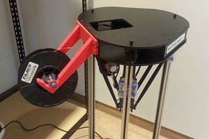
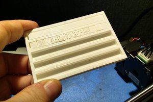
I've aluminized the dish, mounted it to a tripod, and tested it out. Pics:


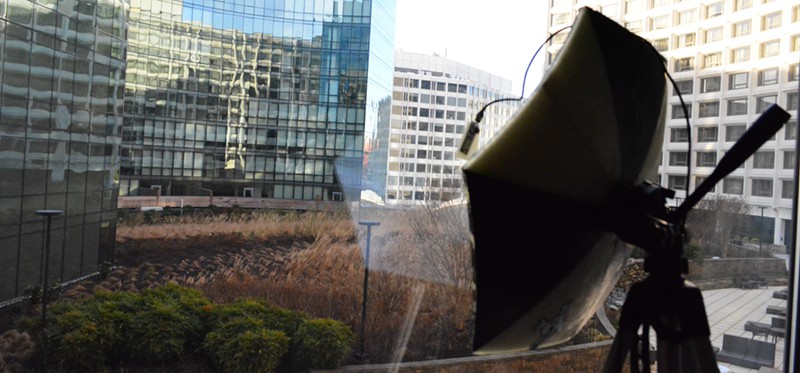
I've also written a post on this for Hackaday. You can check that out here.
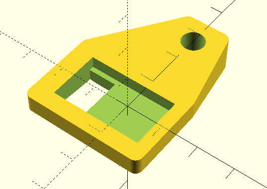
The center mount has a single 'stovepipe' that allows me to attach a pole for the feedhorn. This is the other end.
It's designed to hold an ESP-01 module so that the antenna is directly in the center of the dish.
$fn = 64;

module esp8266(){

 union(){
     translate([0,-4,-2])
     cube([14.7,25,11], center=true);

     translate([0,-12.5,6])
     cube([12,8,12], center=true);
 }
}

module pole(){

 translate([27, 0, -21])
 cylinder(d=6.40, h=30);

}

module holder(){
   difference(){
        hull(){
            translate([32,0,0])
            cylinder(d=4, h=10);

            translate([32,5,0])
            cylinder(d=4, h=10);

            translate([32,-5,0])
            cylinder(d=4, h=10);

            translate([10,10,0])
            cylinder(d=4, h=5);

            translate([-10,10,0])
            cylinder(d=4, h=5);

            translate([-10,-20,0])
            cylinder(d=4, h=5);

            translate([10,-20,0])
            cylinder(d=4, h=5);
        }

        esp8266();
        pole();

    }
}


holder();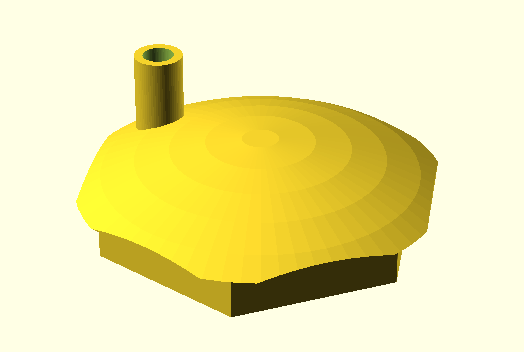
Meant to hold a 1/4" dowel for the extnetion.
Hexagon code from Chris Bate
Uses 1/4-20 flange mount insert on the back, designed for camera tripod
//
//  Center mount for 3D printed parabolic antenna
//  hackaday.io/project/18866
//  Brian Benchoff
//
//  uses hexagon code from Chris Bate:
//  https://www.youtube.com/watch?v=KAKEk1falNg
//
$fn = 64;


module phex(wid,rad,height){
hull(){
        translate([wid/2-rad,0,0])cylinder(r=rad,h=height);
        rotate([0,0,60])translate([wid/2-rad,0,0])cylinder(r=rad,h=height);
        rotate([0,0,120])translate([wid/2-rad,0,0])cylinder(r=rad,h=height);
        rotate([0,0,180])translate([wid/2-rad,0,0])cylinder(r=rad,h=height);
        rotate([0,0,240])translate([wid/2-rad,0,0])cylinder(r=rad,h=height);
        rotate([0,0,300])translate([wid/2-rad,0,0])cylinder(r=rad,h=height);
    }
}
module plug(){
    difference(){
    cylinder(d=12,h=30);
    translate([0,0,-1])
            cylinder(d=6.40,h=25);
    }
}


module metaAdapter(){
    union(){
        translate([0,0,10]){
            difference(){
            phex(68,0.1,20);
                translate([0,0,21])
                    phex(64,0.1,19);

                translate([0,0,1])
                    cylinder(d=8,h=20);

                translate([0,0,18.5])
                    cylinder(d=20,h=5);

                translate([0,15,1])
                    cylinder(d=4,h=25);
            }
        }
        intersection(){


            translate([0,0,-10])
            phex(80,0.1,20);


            translate([0,0,50])
               sphere(d=120);
       }

       translate([27,0,-20])
        plug();
    }

}


module adapter(){
    difference(){
        metaAdapter();

        translate([20,13,-15])
        cylinder(d=10, h=50);

        translate([20,13,22])
            rotate([-90,0,-60])
                cylinder(d=10,h=10);

        translate([27,0,-20])
            cylinder(d=6.4,h=40);
    }
}


adapter();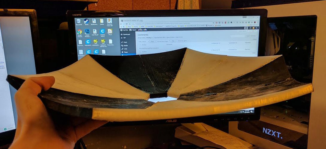
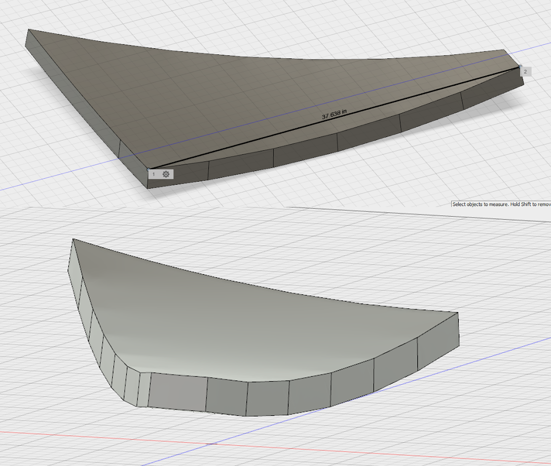
The dish is printed. only thing left to do is add the center mount, metalize the dish, and place the feedhorn.
The diameter of the dish is 49mm, which means the depth of the dish is 6mm. We're dividing everything by two here (units are arbitrary), so the feed horn must be 25mm from the bottom of the dish. This means the feed horn must be 19mm above the 'points' of the dish.
Knitting needles and hot glue.
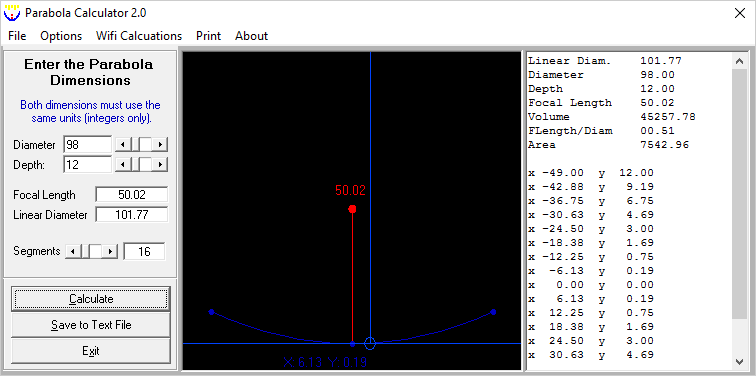
diameter 98, depth 12, Focal length 50. Units are arbitrary.
I scaled this 500% when 3D printing it, so the actual specs are:
490mm diameter, 60m depth, focal length 250.
What do we end up with?


Thats really tidy, nice work. Makes mine look horrible lol. https://hackaday.io/project/19582
 haydn jones
 Dongil Choi
Good day to you !
FANTASTIC PROJECT !!!
2 things though;
1. Where do you solder the wires onto the ESP-01 module to be able to use this antenna ?? unclear.
2. Just curious and not quite understanding the two ESP Programming Sketches, what exactly are the for and what do they do, just this extra description would be greatly appreciated and many thanks in advance, sorry if this question sounds silly for an obvious answer but i am still learning about this ESP8266 platform and struggling a lot as, well, um... im old lol
Thanks LOADS in advance, really also be grateful for positive responses, if you lot on the internet aint got anything nice to say then STFU and keep it to yourselves LOL !