Lithium ION
I wrote a full tutorial on 555Ic in which astable mode of the IC is explained. That how we can change the output frequency and duty cycle as per needs. And today I also have a similar topic that is testing of servo motor using Ne555 IC, because the servo motor work on a mechanism of PWM signals. by changing the duty cycle of the signal we can control the motion/ rotation of a servo motor. What ever is the frequency but the PWM signal should have exact on/ off time.
Using this method we can easily test the servo motors just plugging them into the PCB board. No need of any type of microcontroller or programmable device. In last we will design the PCB shield for it, I am using PCBWAY prototyping service for a long time. They provide very good quality PCB in very low price, just $5 for 5 pcs of 2layer board.
Basic idea of working:
The duration of the pulse provided to the Control Pin will decide the angle of rotation of the servo. We know that most of the servo motors available today can be rotated from 0 degrees to 180 degrees. When the duration of the pulse is 1 milli second (1 ms), the shaft of the servo is rotated to 0 degrees.
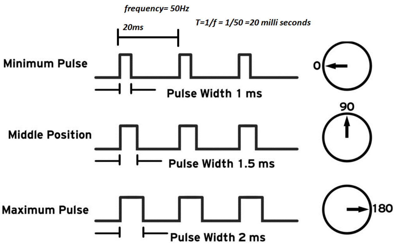
If the duration is increased to 1.5 milli seconds (1.5 ms), the servo rotates to 90 degrees. This is the default position. When the duration of the pulse is further increased to 2 milli seconds (2 ms), the servo rotates all the way to 180 degrees.
555 in astable mode:
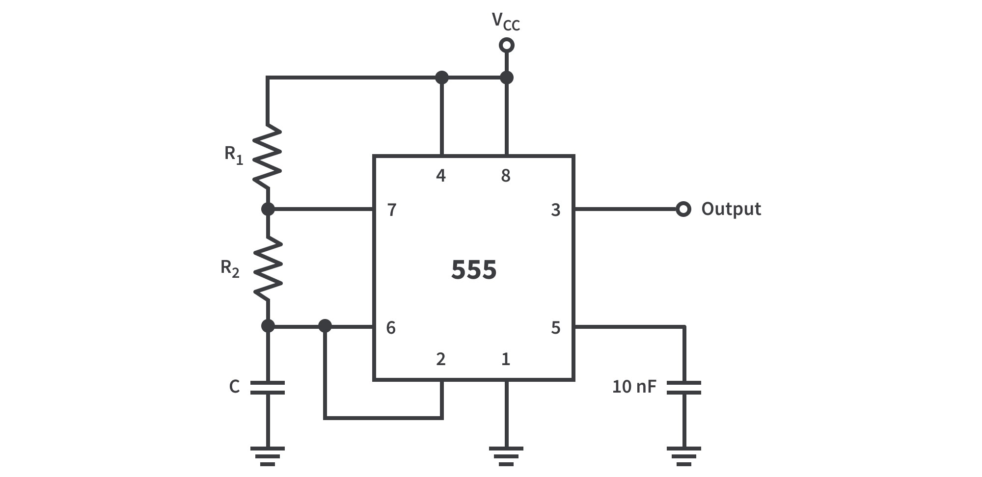
In the astable mode of this IC, the following circuit diagram is used. Capacitor is connected to 2, 6 pin. Reset pin(4) is connected to VCC(8). Trigger(2) to Threshold(6) to make a loop or auto trigging circuit. Control voltage(5) is connected to ground with a bypass capacitor to avoid any noise. One resistor R1 is connected between pin 6 to 7 ( Threshold to discharge) and R2 is between 7 and 8(discharge and VCC). This configuration is only used for a stable mode to generate a specific frequency with fixed duty cycle. Know more about astable multi-vibrator from here.
Components required:

- 555 Timer IC
- 1k, 4.7k, 6.8k, 10k, 36k resistor
- Tactile switch
- 100nf ceramic capacitor
Circuit diagram:
I put the circuit in astable mode and you can see the modified schematics according to that given here. In this circuit 100nf capacitor is used to generate the frequency, and by using the two resistor combination with tactile push button we can change the duty cycle of the output wave.
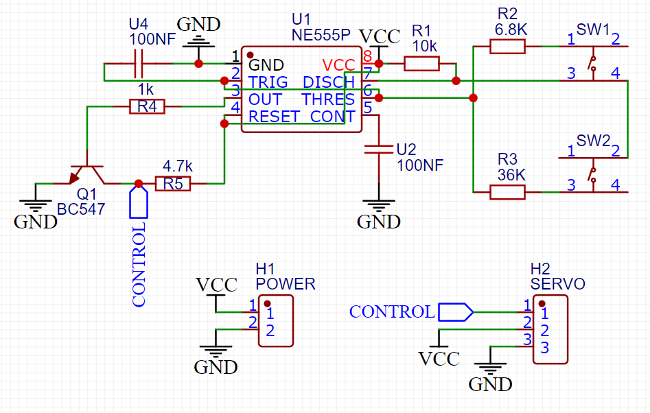
According to the duty cycle servo motor should change the position. but we need a NPN transistor in switch configuration at the pulse input (PWM) pin. This base of transistor is connected to the PWM output and Servo motor control pin is connected to the collector part of it.
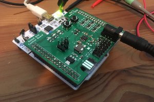
PCB design and specs:
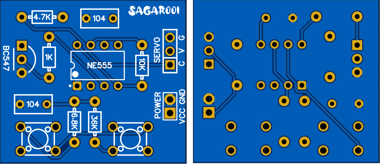
I designed a small dual layer PCB according to the above given schematics. You can use PCBWAY prototyping service for this, PCBWAY is the leading PCB manufacturer in China and provide a huge range of PCB services. Like PCB assembly, PCBA, stencil, 3d printing and custom SMT assembly services. Download all the required files from here.

In this small PCB you will find two tactile switches and which are well labeled. The output can be taken through the 3 pin headers. On the one side of the PCB 2 pin header for the battery connection. Participate in Christmas project design competition and get free coupons up to $100.
Working and testing:
As the button 1 of the shield is pressed the servo start from the initial position and heads towards the positive direction and in the similar way 180 action is there with second tactile button.
 Arduino KIT
 Daphne