 Antonio Lopez
The project is about building a robot capable of playing beer-pong, for which it has been decided to implement a catapult that is capable of launching a pingpong ball into a cup located one metre away. For which two sub-systems have been implemented, the first one is the launching system which has the mission to launch the ball, while the second one has the mission to rotate the base so that it is able to launch from [0-180] degrees.
For the first sub-system, launching, we start with the parabolic launch equation, in order to know the launching speed required to reach a certain distance (no friction was considered).
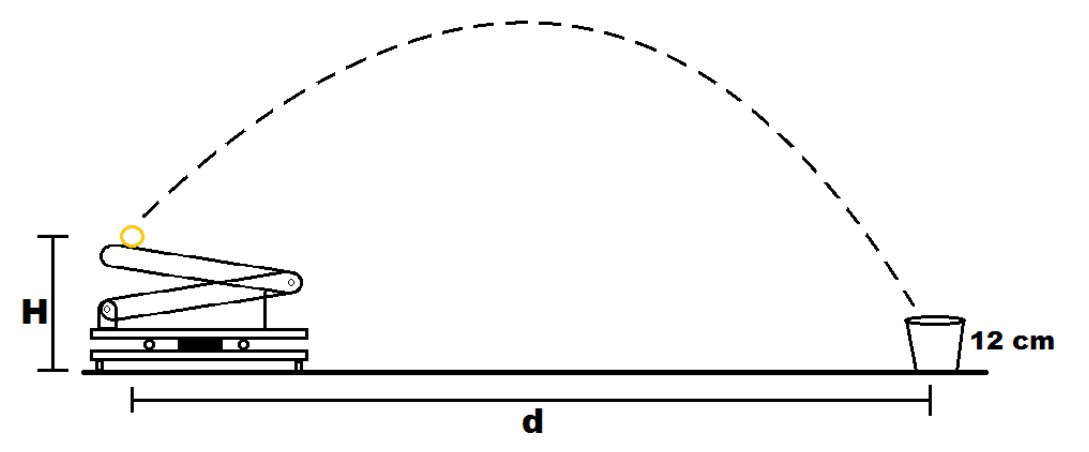
In this case we have the following equations for the motion on the x-axis and on the y-axis, for which we can take off the time and leave everything around the velocity variable. The resulting equation is as follows.
- d total distance
- theta launch angle
- H height of the launch.
- h height of the cup.
- w RPM that we need in the moment of the launch
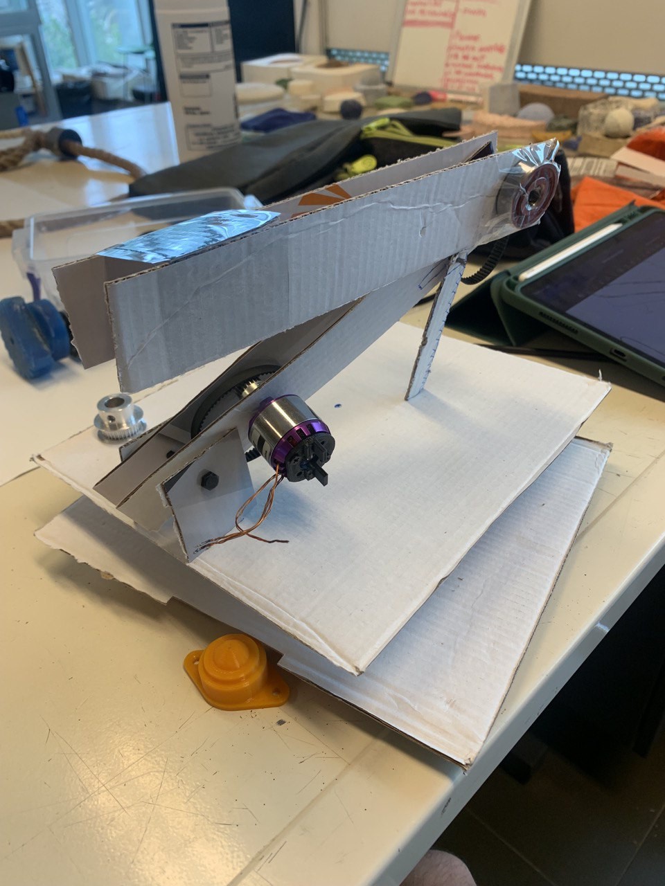
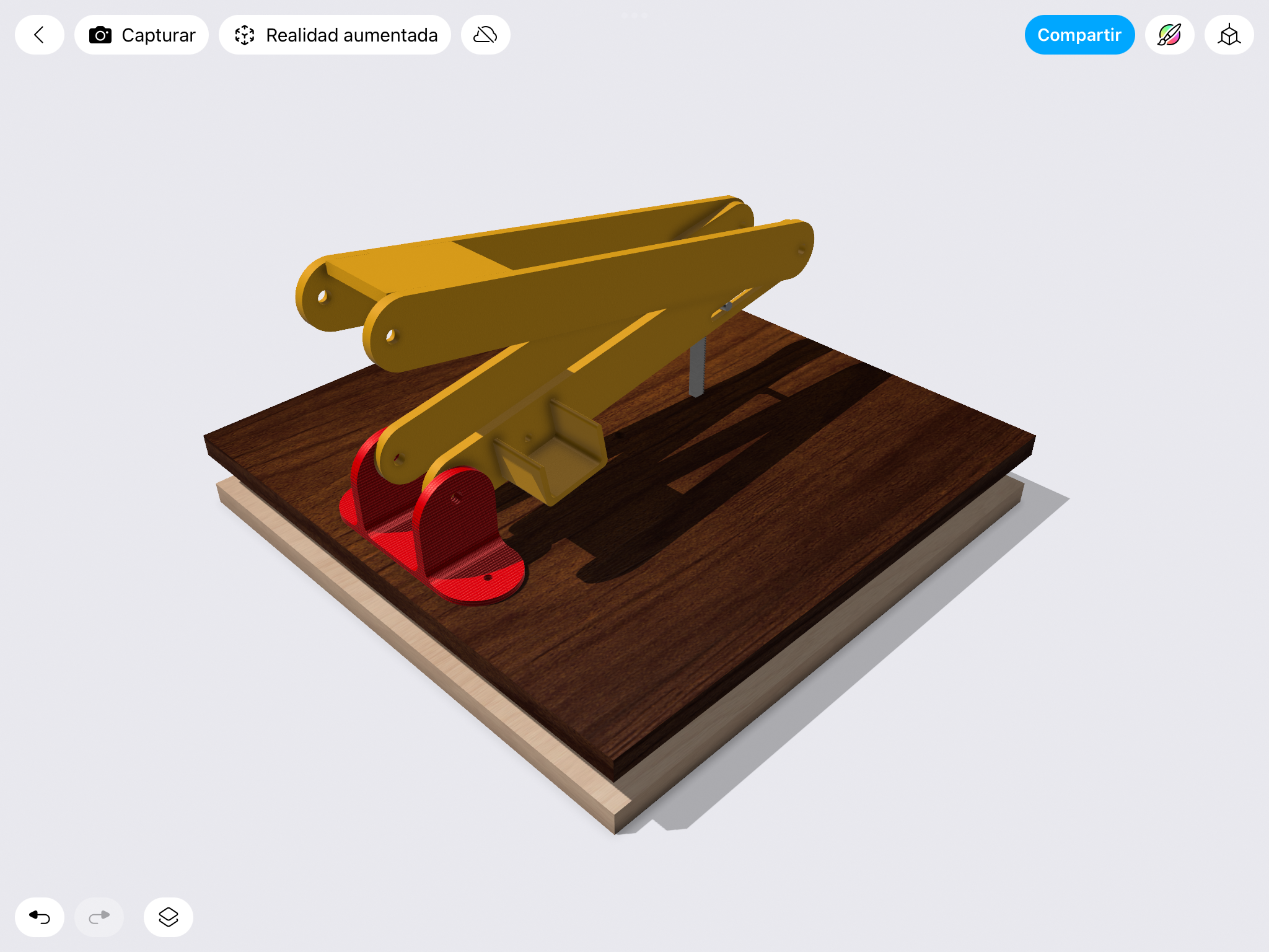
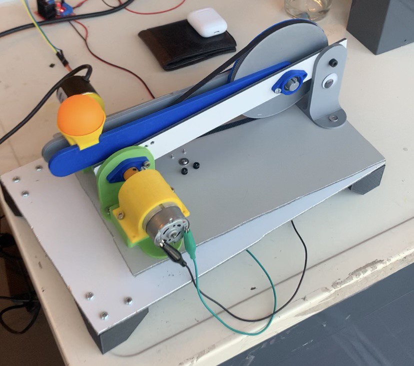
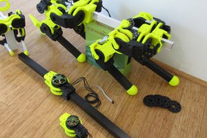
Then to get the ball up to speed a launch system was created consisting of a 0.2[m] arm attached to a toothed pulley with a diameter of 0.12[m] this pulley is attached to a smaller pulley of 0.012[m], so it is a reduction of 1:10 rpm. This is because the engine speeds were very high.
For the second subsystem we used a much simpler function implemented in Arduino (atan) which allows to identify the angle from the initial coordinates, and then deliver this angle to the servomotor.
The launch point of the system was limited by two variables, the first being the velocity and the second being the launch position which was set to a maximum of 90 degrees or the vertical axis. Initially we tried to implement a PID control for the launch speed, however by not making a correct selection of the initial motor there were problems for the control, this added to the fact that the time in which the motor would rotate was really short before the position variable was breached, the Arduino was not able to maintain optimal control, giving very long term results which was useless for this application.
So it was limited to choosing the position control with the help of the encoder in order to slow down the motor and allow the ball to shoot out.
The encoder allows counting the relative position around an initial point, thanks to a sensor and measuring how much this changes. In this way we can know the position and thus control the moment of launch (being able to calculate an approximate angle), the encoder in this case was 600 pulses so that when we wanted to brake the arm to a position of 90 degrees we had to have an approximate of 4 complete turns giving an approximate pulse of 2400 pulses more than there was in the beginin.
In the same way, a time range could be used to count how much progress was made and thus obtain the RPM, using the following equation.
We also enter the instructions to reload the launch by inverting the IN1 and IN2 inputs of the H-pin.
To go from distance to RPM and then to the PWM value to be delivered to the DC motor, the Arduino map() function was used. However, these results were not as expected, given that the acceleration curve of the motor was not considered, which did not allow the desired RPM to be reached, so a direct transformation from distance to PWM values had to be used. The values that were used for the PWM to behave in a stable way had to be high. Distance was between 30-117 [cm]PWM should be between [190-255], in order to reach a higher distance.
The results seen for a 24V power supply can be seen below
 Paul Gould
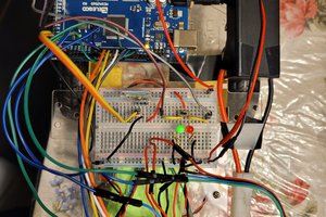
 Ghani Lawal
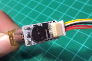
 Danny FR
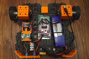
 matop
matop