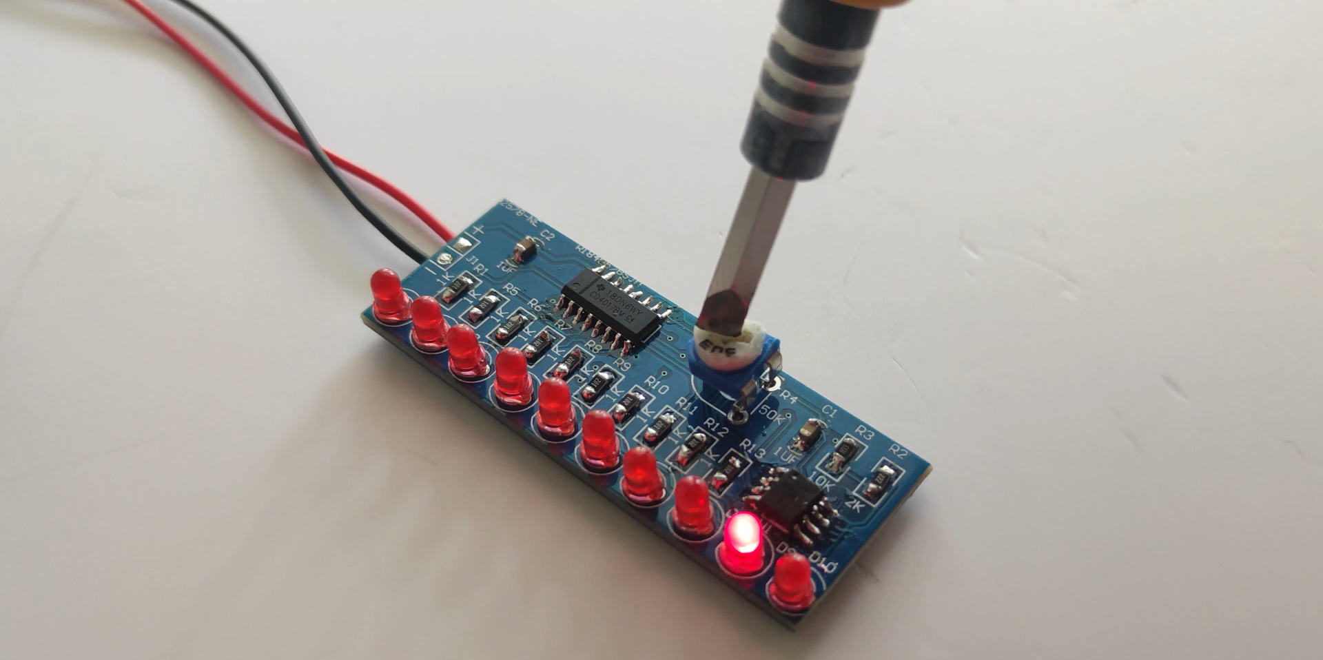
6 channel LED chaser is based on LED flashing, If you want to build a 6 LED Chaser circuit we suggest this circuit first. It uses popular IC is a simple and affordable IC-4017 decade counter and IC-555. When we power the circuit, LEDs start glowing one by one for a defined time period. Means first LED Q1 glows and then Q2 glows and Q1 turned OFF and then Q3 glows and Q2 turned OFF and so on. When we change resistance of variable resistor then speed of LED's increase. Because frequency of 555 timer increases and this increases frequency signal is directly connected to counter's trigger pin
This is the circuit of a simple LED chaser. The LEDs lights one by one for a period of 1second and the cycle repeats giving the running light appearance. The circuit uses two ICs (one is 555) to drive the LEDs.
IC1 (NE555) is the popular timer IC wired in the Astable Multivibrator mode. Resistors R1, VR1 and capacitor C1 act as the timing components and the output pulses are available from the output pin 3 of IC1. These pulses are given to the input pin 14 of the Johnson decade counter IC CD4017. Out of the 10 outputs of IC2, eight outputs are used to drive the LEDs. The ninth output pin 9 is connected to the reset pin 15 to stop the counting. So that the cycle repeats. With the value of C1, each LED remains on for 1second. When one LED turns off, the second on turns on. This cycle repeats giving the running light appearance. Resistor R3 keeps the input pin 14 of IC2 low after each pulse.VR1 adjusts the speed of LED chasing.
Meanwhile, the working operation of this circuit is simple and adorable. Here, we have likewise employed a 555 timer IC in Astable mode for creating a trigger pulse for a short time span. Henceforth, a variable resistor is associated with changing the cycle frequency of the 555 timer yield. However, a CD4017 counter IC is additionally related to this circuit to give the LEDs a lighting effect.
Also, the ten red LEDs are further associated with Q0-Q9 (pin 3) through a 150-ohm resistor. MR (pin 15), and 555 timer pin (pin 13) are legitimately associated with ground and likewise, the output pin of the counter is straightforwardly associated with the yield pin of 555 Timer. Thus, the circuit gives a blinking effect in a sequential manner. You can likewise change the speed of LEDs with the help of a 10k Pot.

This circuit can likewise be used in many applications from home decoration to security alarms. Meanwhile, the most popular application of LED Chaser circuits is deployed in advertising displays, running light ropes, and in small discos. Additional applications are in Knight riders, decoration of home, shops, and likewise parties and occasional lightings.
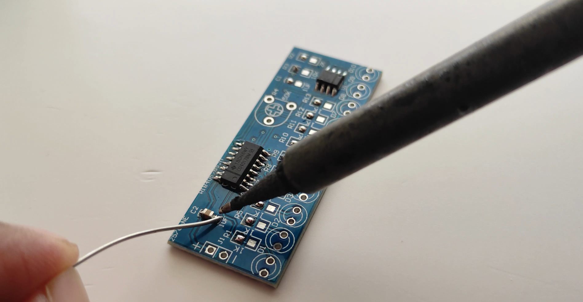
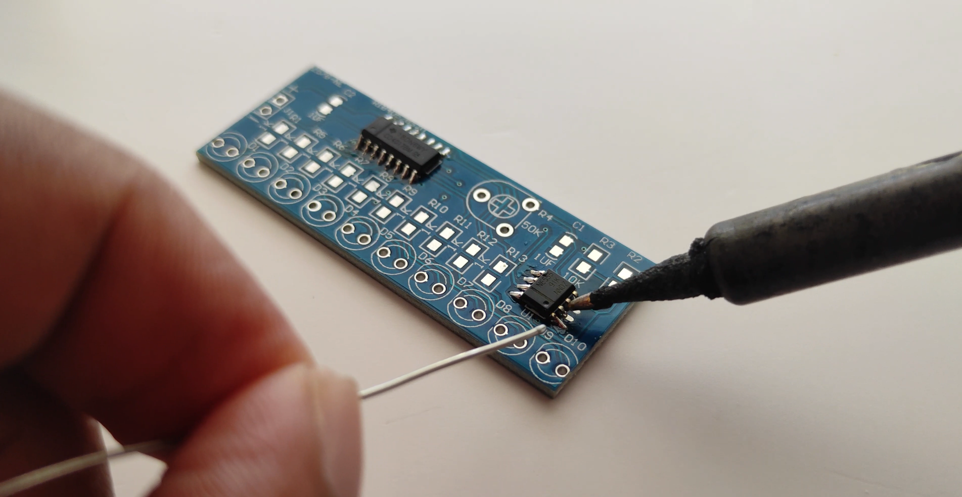
To make this simple LED chaser circuit I have used a 555 timer & 4017 IC. Here the 555 timer IC will generate the clock pulse for CD4017 IC. Then 4017 IC will blink the LEDs in sequence as per the signal in the clock pin (14).
I have used a 5V DC supply, but you can also use the 12V DC supply (no changes required for 12V).
An LED chaser or sequencer is a popular LED driving circuit. It’s used in running-light rope displays to flash different lighting patterns. In a chaser or sequencer circuit, a controller commands the sequence and timing of the flashing LEDs to illuminate different kinds of lighting patterns.
This LED chaser is built on Arduino UNO. Arduino is currently the most popular single-board microcontroller. In this sequencer, seven LEDs are interfaced with Arduino to demonstrate 13 different lighting patterns.
In fact, it’s possible to design an LED chaser with several LEDs by using shift registers. In this LED chaser, LEDs are directly interfaced to Arduino pins since Arduino’s GPIO can output forward voltage and the current required to switch them ON/OFF.
The LEDs are controlled via the digital output from Arduino. The UNO is programmed to output logical signals with different sequence over its pins with...
Read more »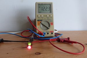
 MagicWolfi
 Sam Ettinger
 Hulk
Hulk
 Yann Guidon / YGDES