ElectronicABC
GERBER PCB:
https://mega.nz/file/mRxwlYhA#uEpgoR9pM2MKJ1_jfyn2-iOhDwTkpTD5l5GbN974_j8
SCHEMATIC DIAGRAM
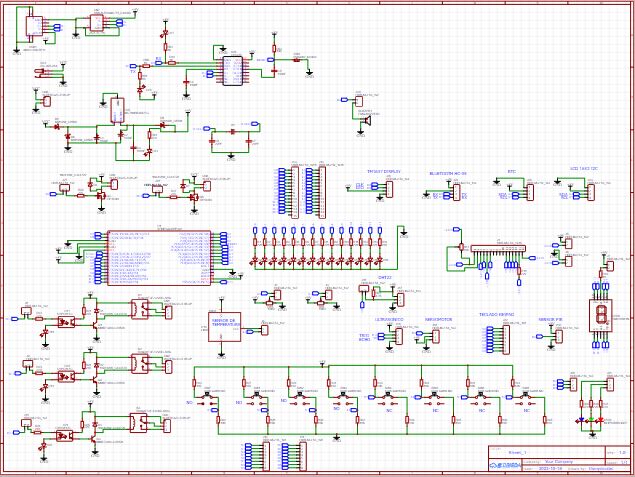
Here we see the schematic diagram with the values of each component that we will use for our project
FUNCTIONING
First, let's start with the atmega328p-au microcontroller referring to the arduino nano, this time we have this microcontroller as the main brain of the project since without it absolutely nothing would be done, this microcontroller has analog inputs and digital inputs, so we will make the most of all of it to make our arduino NANO trainer we also have PWM outputs so by analyzing this microcontroller we can control different sensors for our tests and then we can carry out our final projects.
As with any system, we will take into account the programming, for this reason we have included in the PCB the CH340C integrated circuit for computer communication and PCB, all the projects that we develop in the ARDUINO IDE can be downloaded directly.
We include the power supply already reduced to 5v, since our microcontroller needs that voltage to work, we can use a 9v to 12v source as input for powering our PCB.
This project is worked to do the tests also with the LDMICRO software for the ladder language or also that it works as a PLC for which we integrate PULL-UP and PULL-DOWN inputs to simulate NC inputs and NO inputs and as digital outputs we have 3 outputs a RELAY can control 220VAC.
The sensors or modules that we can control are the following:
- BLUETOOTH MODULE HC-05 or HC06
- I2C LCD MODULE
- 16X2 LCD MODULE
-RTC MODULE
- SERVOMOTOR MODULE
- DHT22 MODULE
-PIR MODULE
-KEYPAD MODULE
-ULTRASONIC MODULE
-TM1637 MODULE
But at the same time we integrate some electronic devices on the same PCB such as:
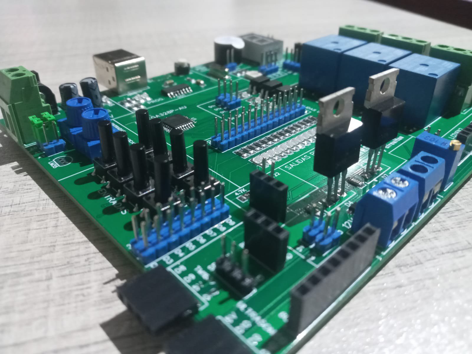
- 3 RELAY outputs
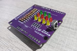
- 1 display COMMON ANODE
- 1 RGB led
- 2 PWM outputs
- 8 digital inputs
- 3 analog inputs
- 13 digital outputs with leds
- 1 buzzer 5v
-lcd16x2
Next we will leave some very easy test codes for this trainer. Later you can give it a more important use and use the modules or sensors that you require.
IMPORTANT:
IF WE NEED TO USE ANY MODULE, WE CAN INSERT IN THE PINS THAT ARE ALREADY ESTABLISHED AND IF WE WANT TO USE ANY INPUT OR OUTPUT, WE CAN PUT THE JUMPER IN THE OUTPUT OR INPUT TO USE IT SHOULD BE NOTED THAT ALL INPUT OR OUTPUT HAS ITS RESPECTIVE LABEL
ATMEGA328P SMD
DESCRIPTION
INFORMATION
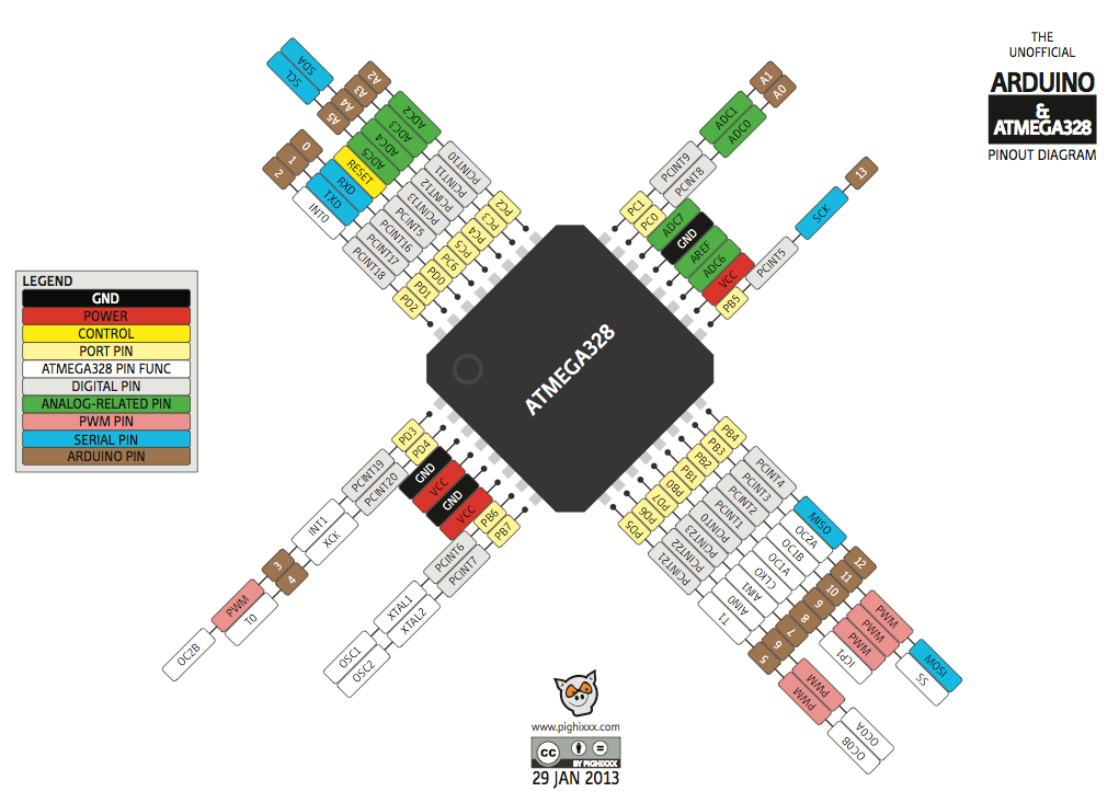
The ATmega328P-SMD microcontroller manufactured by ATMEL (now part of Microchip®) belongs to the AVR® family of microcontrollers with 8-bit RISC architecture, in surface pack or SMD format. It is the microcontroller used in the Arduino Nano/Mini/Pro-Mini/Uno-SMD.
It has features such as: 32 KB read-while-write FLASH memory, 1 KB EEPROM memory, 2 KB SRAM, 23 general-purpose I/O lines, 32 general process registers, three flexible timers/counters with mode comparison, internal and external interrupts, USART mode programmer, a 2-wire byte-oriented serial interface, SPI and I2C, 8-channel, 10-bit A/D converter (2 more than the Arduino Uno), "programmable timer" surveillance" with internal oscillator and five software-selectable power-saving modes. The device operates between 1.8 and 5.5 volts. Its architecture allows it to execute instructions in a single clock cycle, reaching a power of 1 MIPS.
NOTE: It does not come with the Arduino Bootloader preloaded (Optiboot), so it is necessary to program the chip once soldered on the board.
TECHNICAL SPECIFICATIONS
Microprocessor: ATMEGA328P-AU (ATMEL AVR)
SMD Encapsulated Format: 32-VQFN
Pins: 32
FLASH memory: 32KB
RAM memory: 2KB
EEPROM memory: 1KB
Operating frequency: 20 MHz max.
CPU: 8-bit AVR
I/O Pins: 23
Analog inputs (10-bit ADC): 8
Supply voltage: 3.3V-5V DC
Input/output voltage: 5V TTL max.
Dimensions:
Weight:
LINKS
Datasheet Atmel AVR ATmega328P
https://mega.nz/file/nY5mjTYS#FmbJ9FsYGMuZsGYN3Zg6eodBrPeFjqZI4b0USv4BrkI
Official...
Read more »
 Jithin Sanal
 mihai.cuciuc
 Lithium ION