The Tachometer is an RPM counter which counts the no. of rotation per minute. There are two types of tachometer one mechanical and another one is digital. Here we are going to design an Arduino-based digital tachometer using an IR sensor module to detect objects for count rotation of any rotating body. IR transmits IR rays which reflect back to the IR receiver and then IR Module generates an output or pulse which is detected by the Arduino controller when we press the start button. It counts continuously for 5 seconds.
_XaicSmUS44.png?auto=compress%2Cformat&w=740&h=555&fit=max)
An infrared sensor is an electronic instrument that is used to sense certain characteristics of its surroundings by either emitting and/or detecting infrared radiation. Infrared sensors are also capable of measuring the heat being emitted by an object and detecting motion.
The wavelength region which ranges from 0.75 to 3µm is known as the near-infrared region. The region between 3 and 6µm is known as the mid-infrared and infrared radiation which has a wavelength greater higher than 6µm is known as far-infrared.
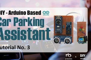
An IR sensor consists of an IR LED and an IR Photodiode; together they are called Photo–Coupler or Opto–Coupler. As said before, the Infrared Obstacle Sensor has a built-in IR transmitter and IR receiver. An infrared Transmitter is a light-emitting diode (LED) that emits infrared radiation. Hence, they are called IR LEDs. Even though an IR LED looks like a normal LED, the radiation emitted by it is invisible to the human eye. Infrared receivers are also called infrared sensors as they detect the radiation from an IR transmitter. IR receivers come in the form of photodiodes and phototransistors. Infrared Photodiodes are different from normal photodiodes as they detect only infrared radiation. When the IR transmitter emits radiation, it reaches the object and some of the radiation reflects back to the IR receiver. Based on the intensity of the reception by the IR receiver, the output of the sensor is defined.
his sensor uses an infrared LED on one side, and there is a photosensor on another side. So when there’s no obstacle between these sides the infrared light reaches the photosensor and gives the signal to the circuit. And this module will output 5V or HIGH state.
But the opposite, if there’s an obstacle between these sides, the photosensor will not detect light and no signal given to the circuit. So the output of this module will be LOW.
So the conclusion is, if there’s an obstacle it will output HIGH
_GqOWjrdsxY.png?auto=compress%2Cformat&w=740&h=555&fit=max)
_5GiTgpn00R.png?auto=compress%2Cformat&w=740&h=555&fit=max)
output pin is directly connected to pin 18 (A4). Vcc and GND are connected to Vcc and GND of arduino. A 16x2 LCD is connected with arduino in 4-bit mode. Control pin RS, RW and En are directly connected to arduino pin 2, GND and 3. And data pin D4-D7 is connected to pins 4, 5, 6 and 7 of arduino. A push button is also added in this project. When we need to count RPM we press this button to start this Arduino Tachometer to count RPM for five seconds. This push button is connected to pin 10 of arduino with respect to ground. You can learn more about the working of IR transmitter and receiver
The unit of measurement of the tachometer is the revolutions per minute (RPM), since you have to understand that revolutions mean turns, then it would be the number of turns that the element makes, for each minute.
The word tachometer has an origin in the Greek vocabulary, the prefix “Tacko” means speed or high speed and for its part, the suffix “Metron” is translated as measure. So, this is why I affirm that the tachometer is an instrument that measures speed.
_gxE0TJKZZY.png?auto=compress%2Cformat&w=740&h=555&fit=max)
_acIku4tfru.png?auto=compress%2Cformat&w=740&h=555&fit=max)
This DIY Tachometer is cheap and works with the principle of Infrared waves. Infrared waves has wavelength longer than the visible light, so they are not visible to our human eyes.
Here we are using an IR sensor module which contains two IR LEDs, one is to emit the IR rays which is called IR Transmitter, and another IR LED which is also called as IR Photo Diode which acts as a...
Read more »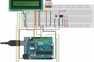
 hIOTron
 Hulk
Hulk