Bharbour
This project kind of grew rather than being designed. A good bit of the direction was based on parts I could get with the chip availability problems of 2022. Last summer, I decided to build a bunch of the cost optimized version of my LED Matrix display driver boards while I could get the parts. When the construction of the boards was complete, I built a test fixture to hold several of the displays, a miscellaneous LED controller board, the I2C mux board and ambient light sensor board. Pretty much anything that uses these displays uses all of these components. The ambient light sensor board is the only "new" design because the previous sensor was unavailable. Having these components all mounted nicely and wired up for doing the driver software development, it occurred to me that it would be a good start on the display for a time server.

Initially, I did not want to use a Linux based system to run the server on. I have a couple of different eval boards for microcontrollers that have ethernet hardware support. The prospects of writing a GPS disciplined Network Time Protocol server to run on a network stack of unknown heritage were not appealing to me. This motivated me toward the Raspberry Pi. All of the display and user interface control would take place via the I2C bus. The GPS (an old Trimble Copernicus II board from previous projects) would interface via the UART and one GPIO pin for the 1PPS signal.
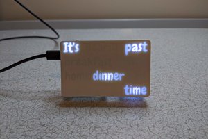
Only 4 of the displays can be run on an I2C bus segment because the driver chips (IS31FL3730) only support 4 choices for their address. Part of the cost reduction that I did on these boards was to remove the expensive I2C bus address translator chips from each display card. Now, I use an 8 way I2C bus multiplexer chip (PCA9547) on a board of it's own to split the I2C bus into up to 8 segments. Two of those segments are used to talk to the 7 characters. The discrete LEDs visible to the left of the top row, between the second and third displays on the top row and between characters on the bottom row are driven by a board using another IS31FL3730 chip. This was done because it is a simple way to control the "miscellaneous" LEDs with a part that I already have driver software written for. The ambient light sensor and the DIP switch board are on separate bus segments because it simplified the cabling. A single byte write to the mux chip is all that is required to select a segment, so the overhead is not bad.
Automatic intensity control for the LED displays is done via the ambient light sensor (VEML7700) chip. The ambient light level is read from the sensor and the result used to look up an intensity value for the LED driver chips from a short table. The contents of this table are empirically derived and there are only 5 different levels at this time. Originally, the ambient light sensor lived on the I2C mux board, but the sensor was completely unavailable (boo, hiss Rohm), so I designed a new board with sites for 2 different sensors from different vendors.
The user interface is done via a 6 wide DIP switch and 2 push buttons. The red button initiates system shutdown and the black one causes the last byte of the ethernet and WIFI addresses to be shown on the display. Only 3 of the switches in the switch pack are used right now:
- 12/24 hour time display format.
- Local or UTC time display.
- Red or Green display.

User Controls, Ethernet Interface and USB Connectors.

A TCA9534 I2C I/O expander chip is used to read the switch settings. All of the switch circuits are protected from ESD damage with TVS diodes to ground. Capacitors to ground protect against RF noise in the switch circuits.
I had a couple of Trimble Copernicus II GPS modules and bare boards left over from previous projects. This module is 10 years old and no longer available, but it speaks reasonably standard NMEA and I had them. The boards that I had left over have a local 3.3V LDO regulator and a place to put an RS232 level shifter...
Read more »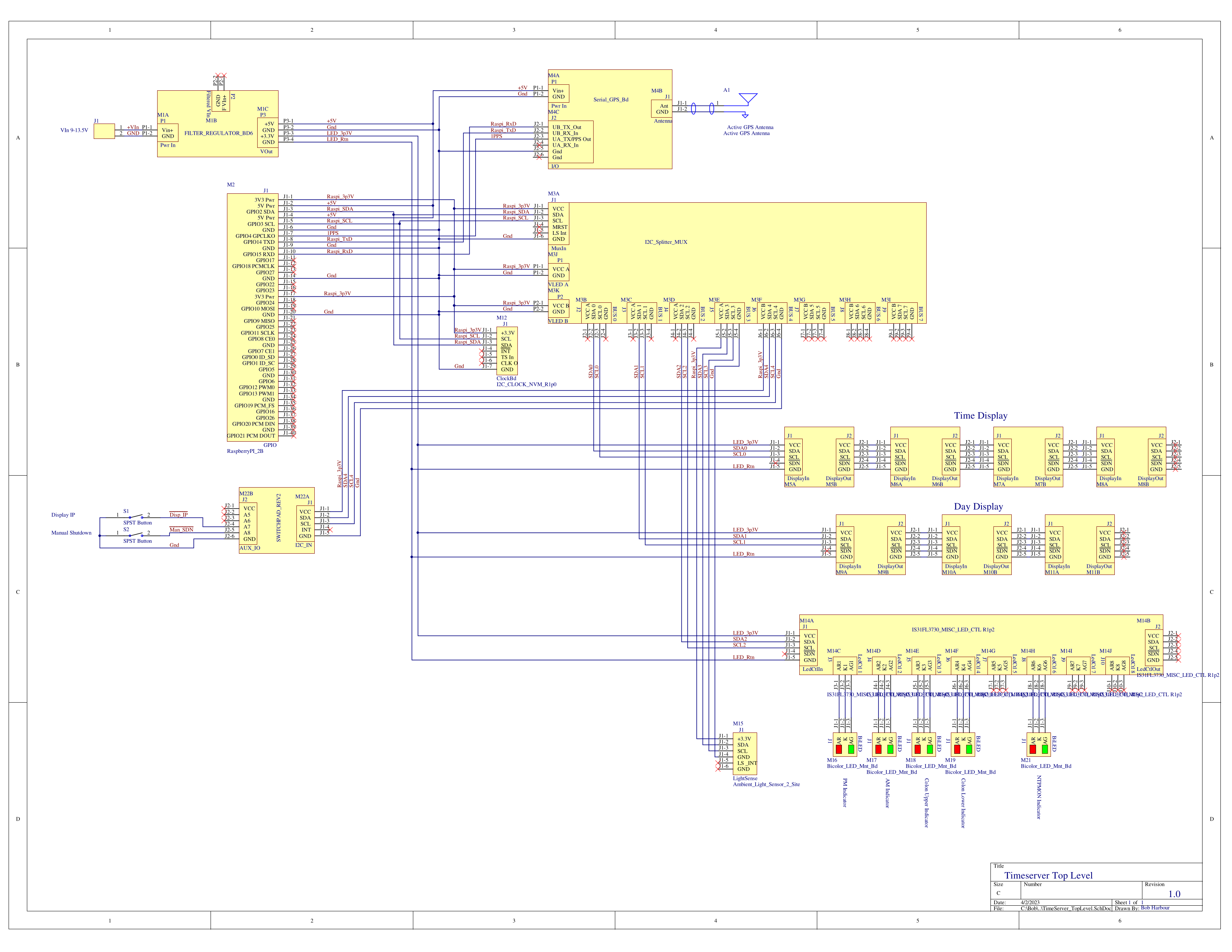


 jens.andree
 Pierre-Loup M.
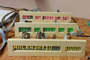
 Atheros