Close
0%
0%

Wee Bug

Fluffbug but smaller

Similar projects worth following

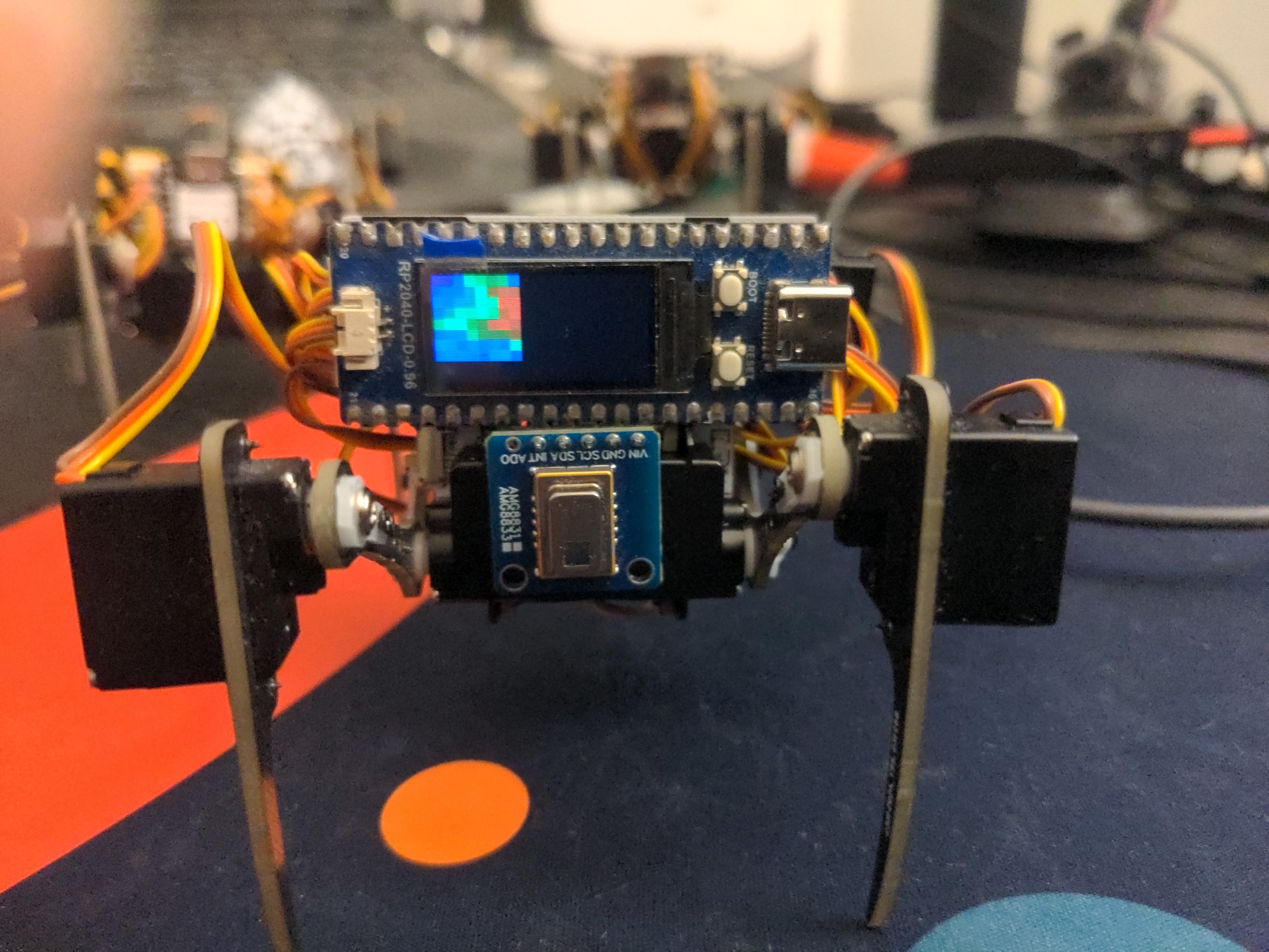
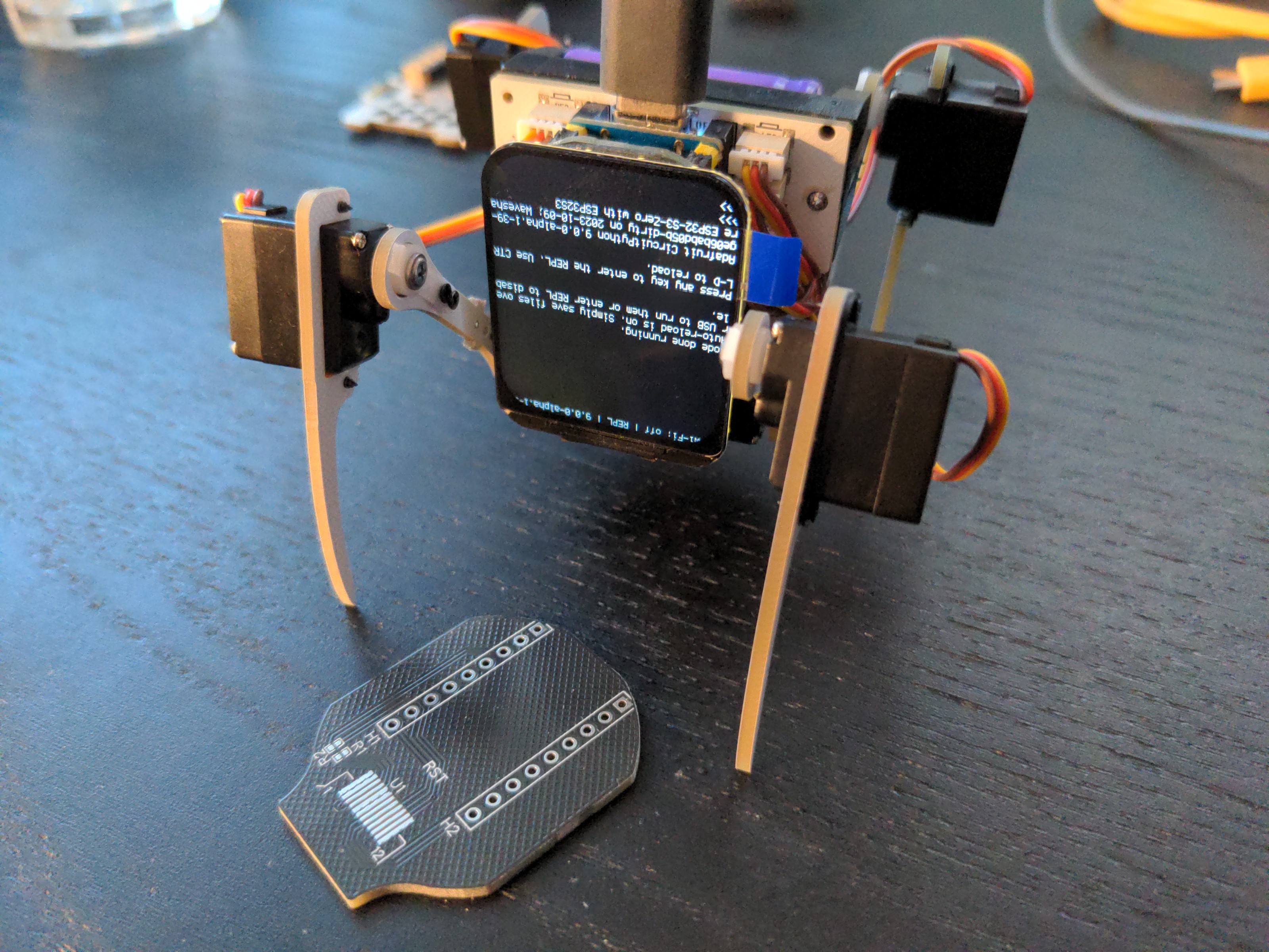
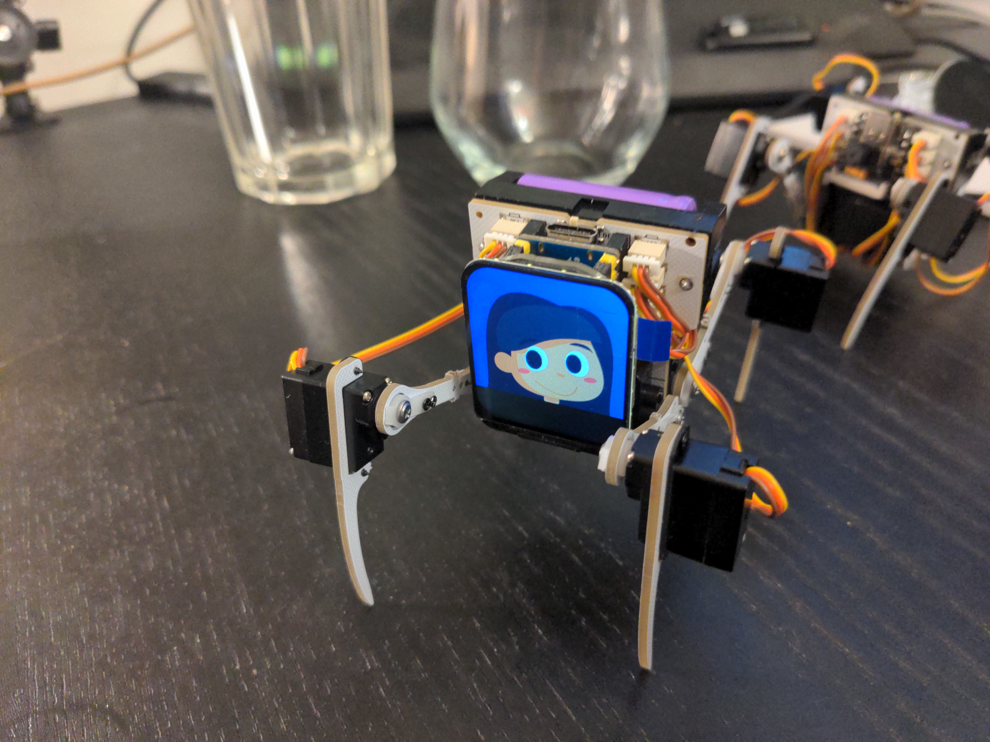
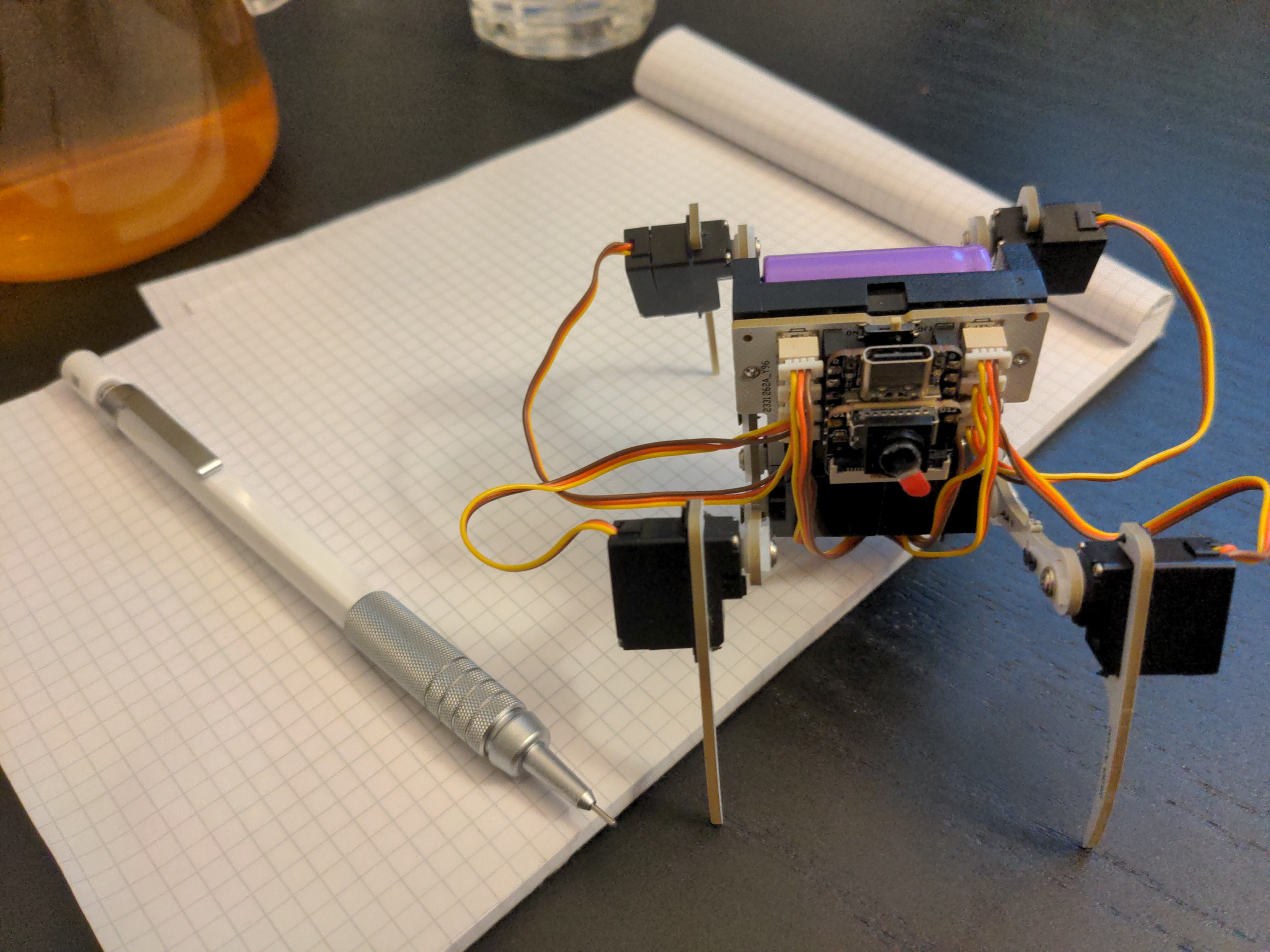
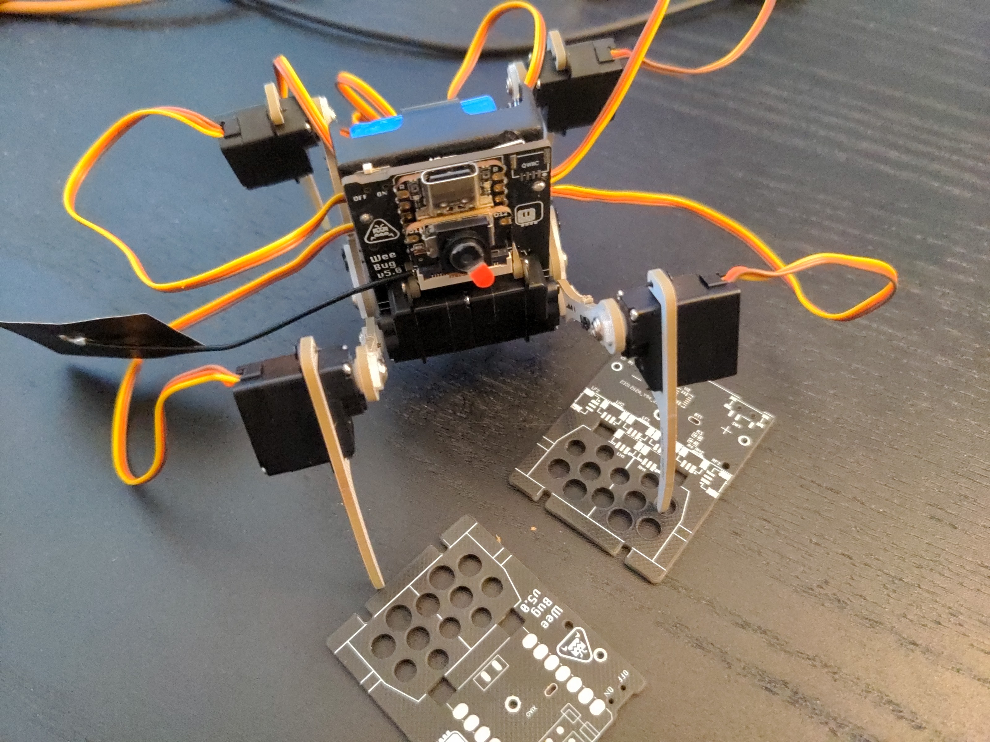
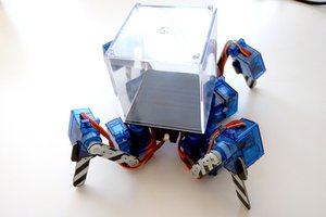
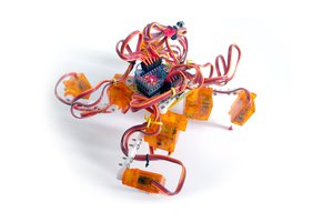
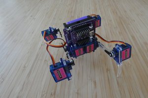
While digging through my drawers, I stumbled upon a bag of sub-micro servos I bought a few years ago from HobbyKing for the #Pony Bot, but never used in the end, because they had wrong connectors. Turns out there are HK-282A servos with 1.25mm-pitch JST connectors and HK-282AS, with 1mm-pitch unidentified connectors. In any case, the Pony Bot is on hold indefinitely for now, until I can find the energy to actually program a gait for it, so I thought that maybe I can use those tiny servos for something else: make a tiny version of the #Fluffbug robot. That would also have the advantage of not needing to write a new gait code, since the one already written for Fluffbug should work.

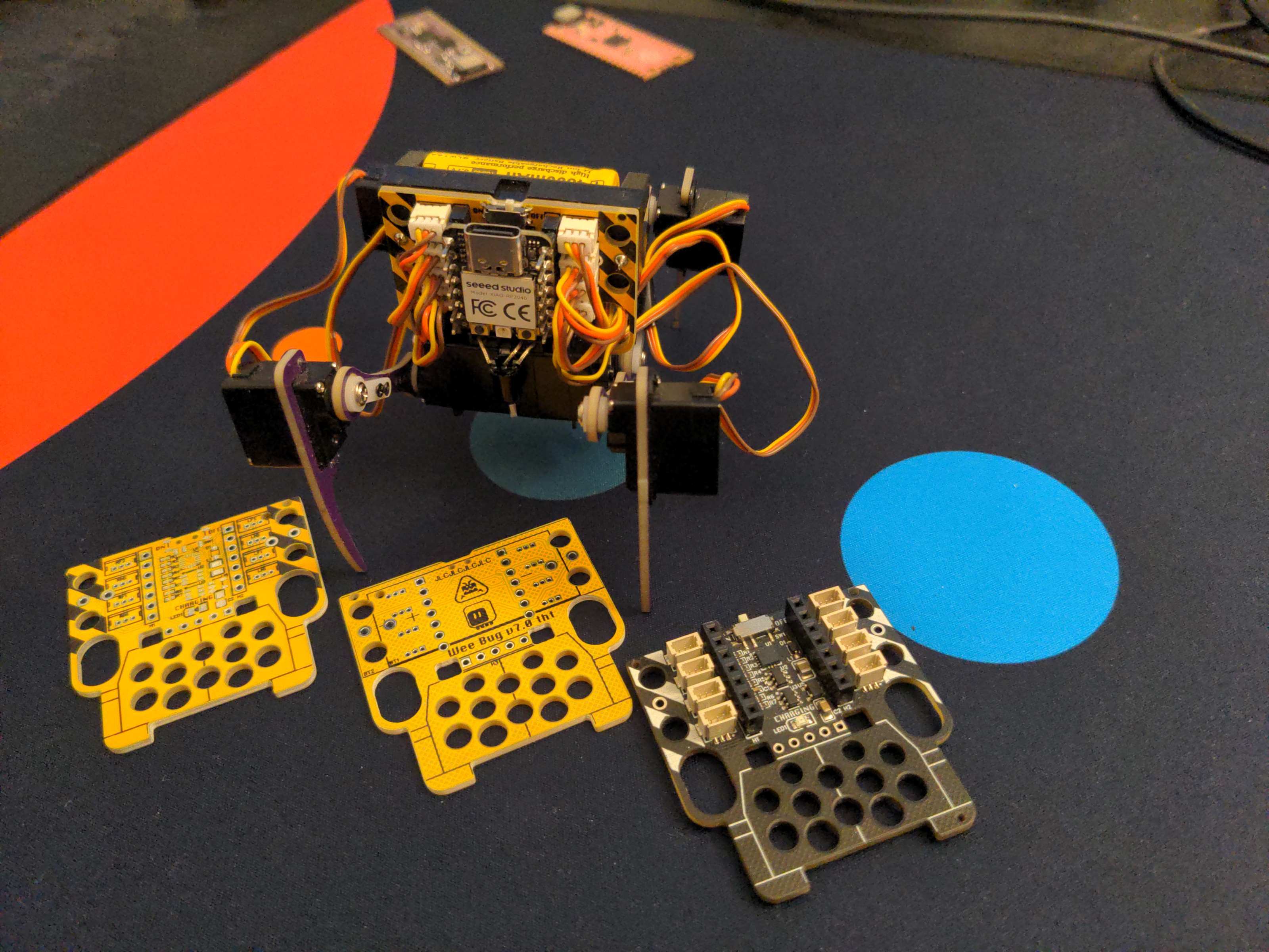
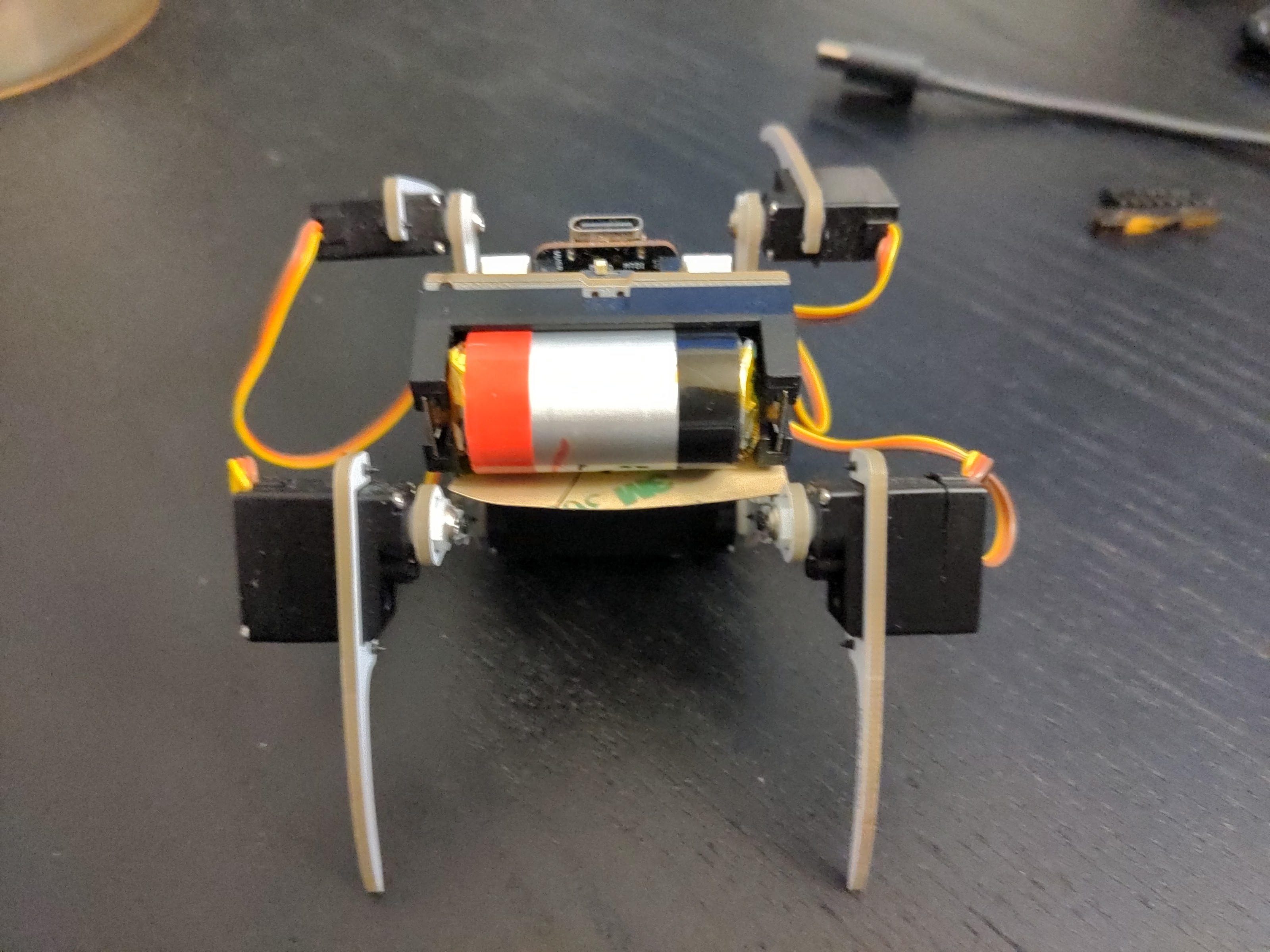
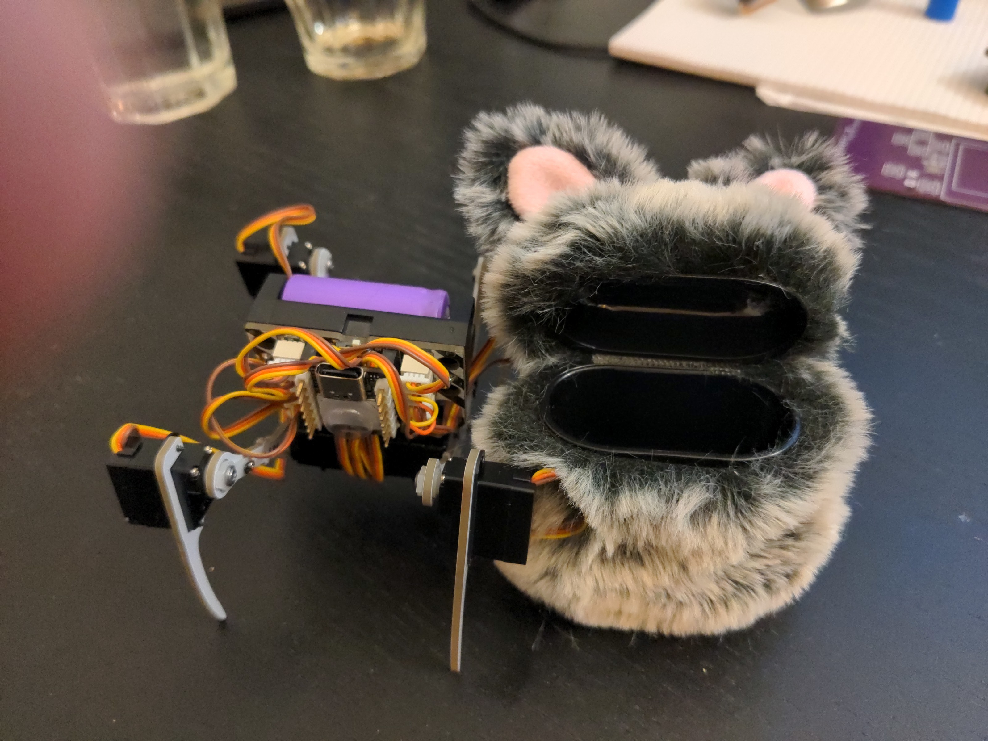
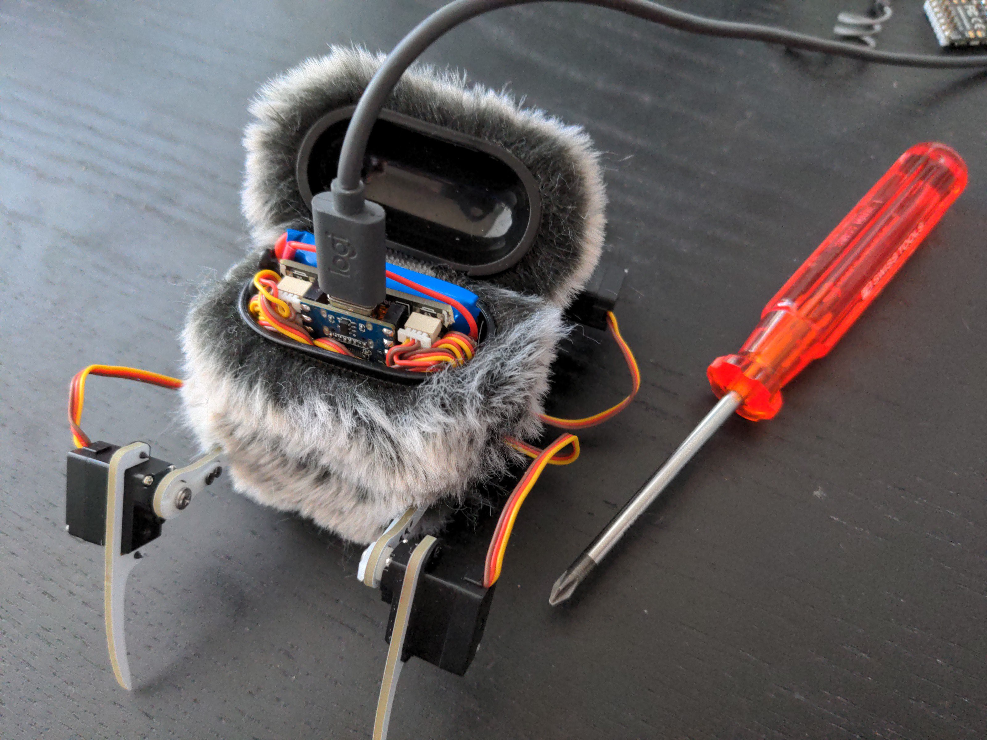
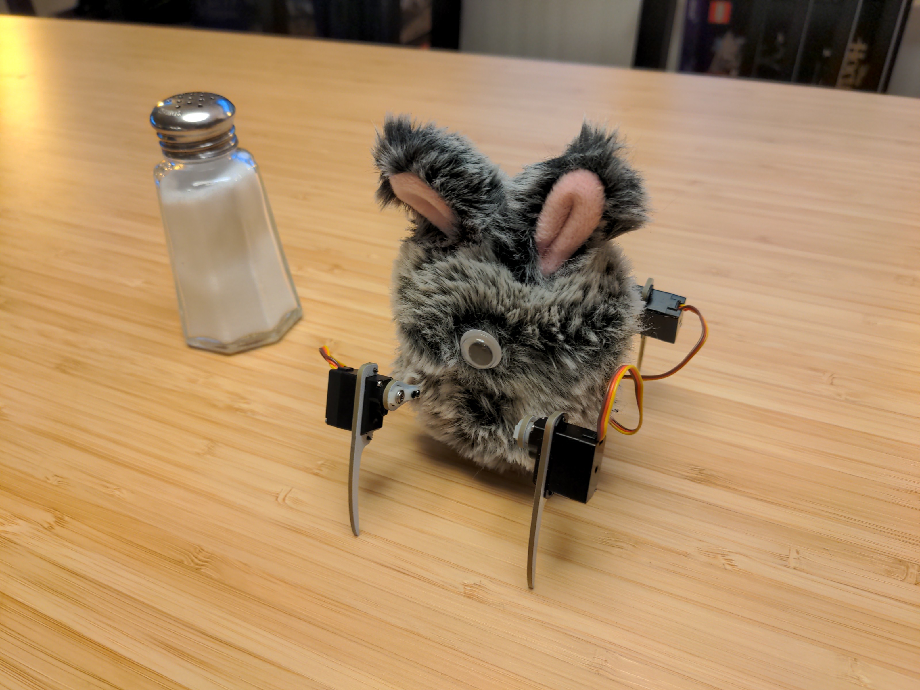
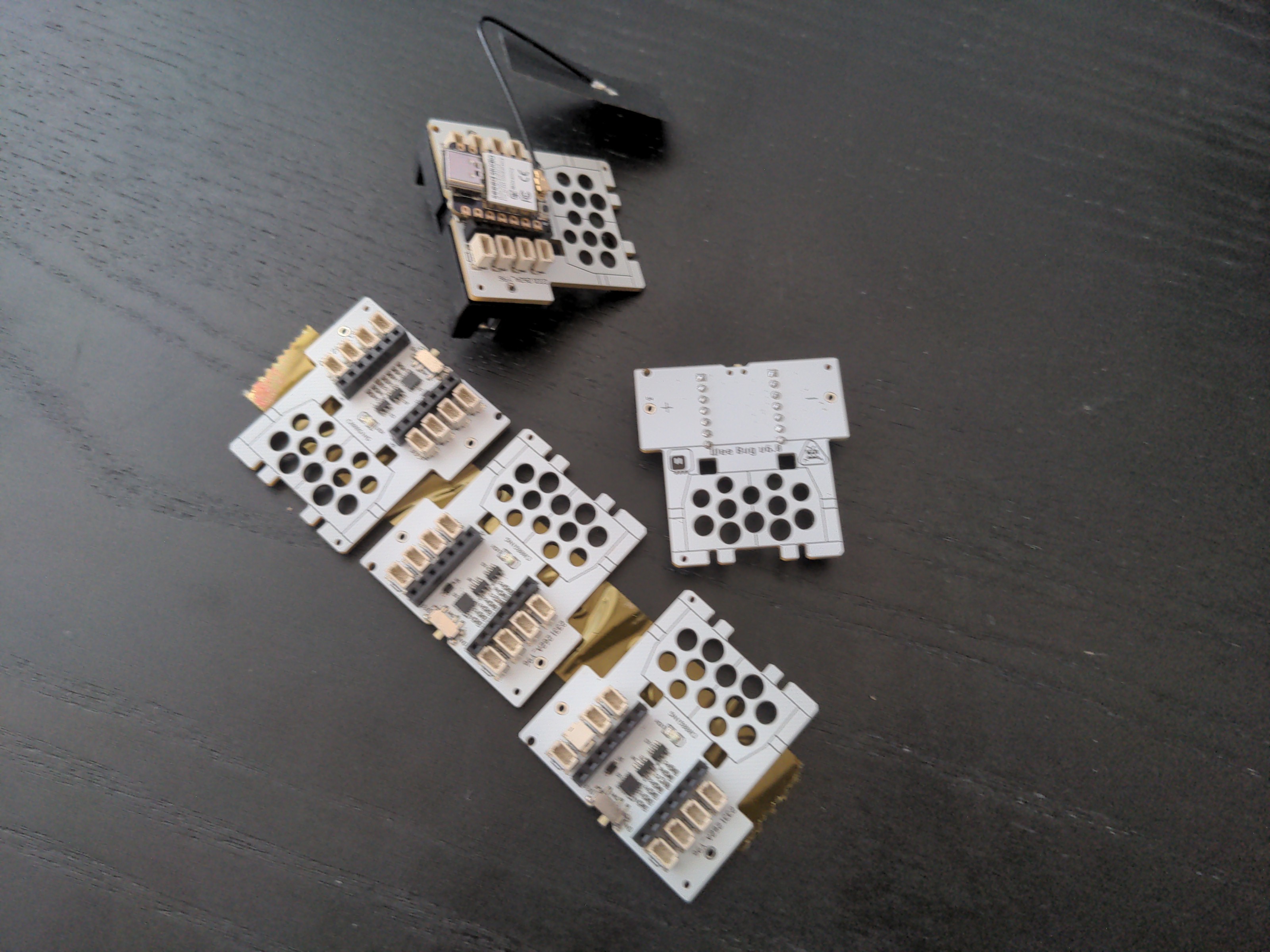
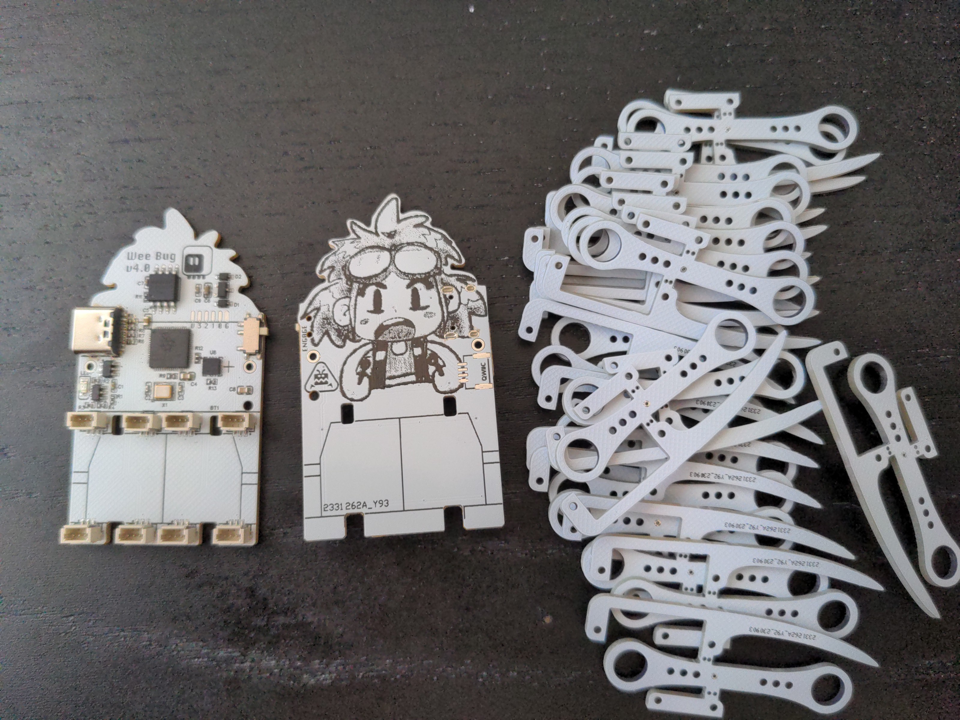
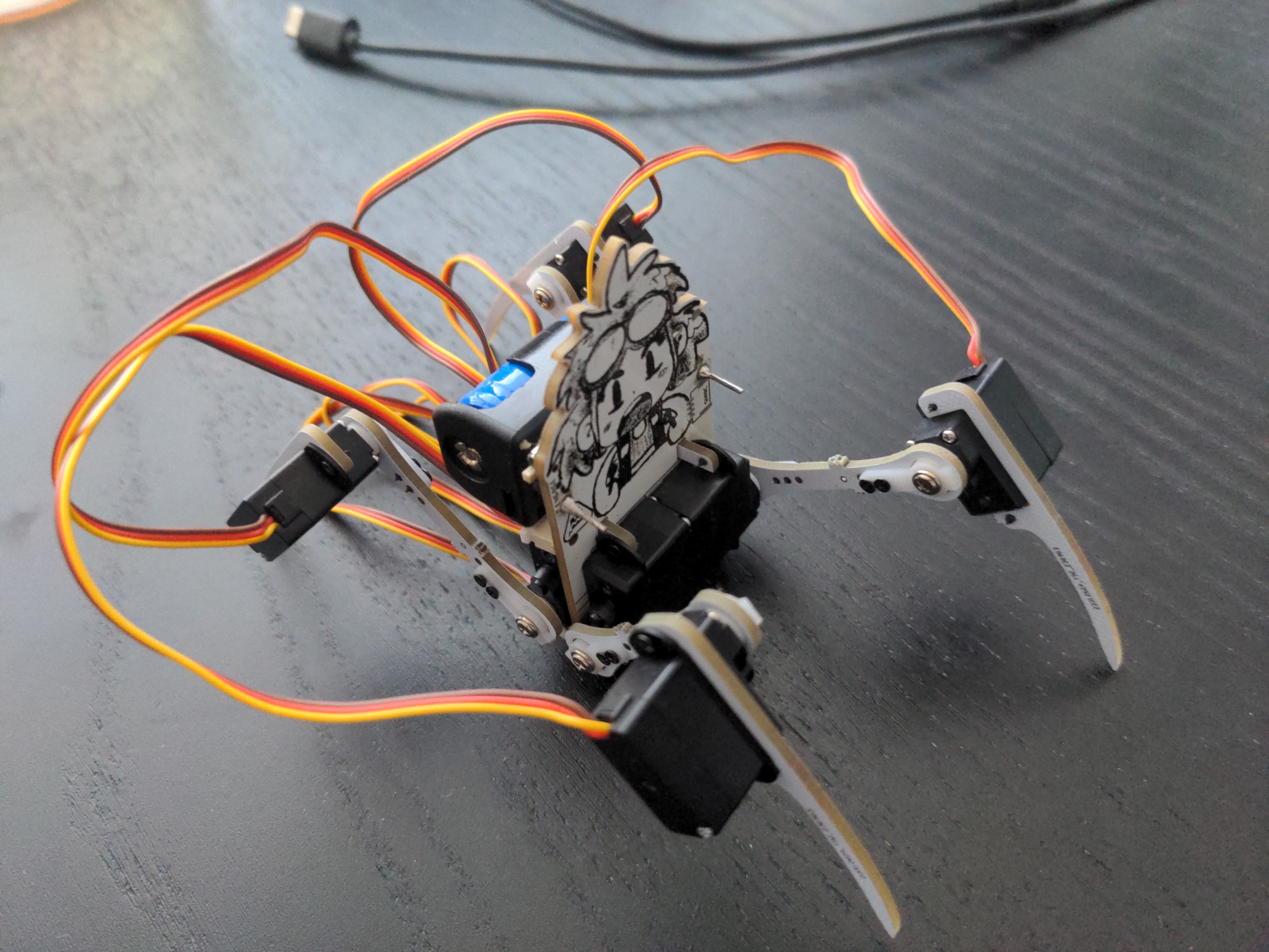
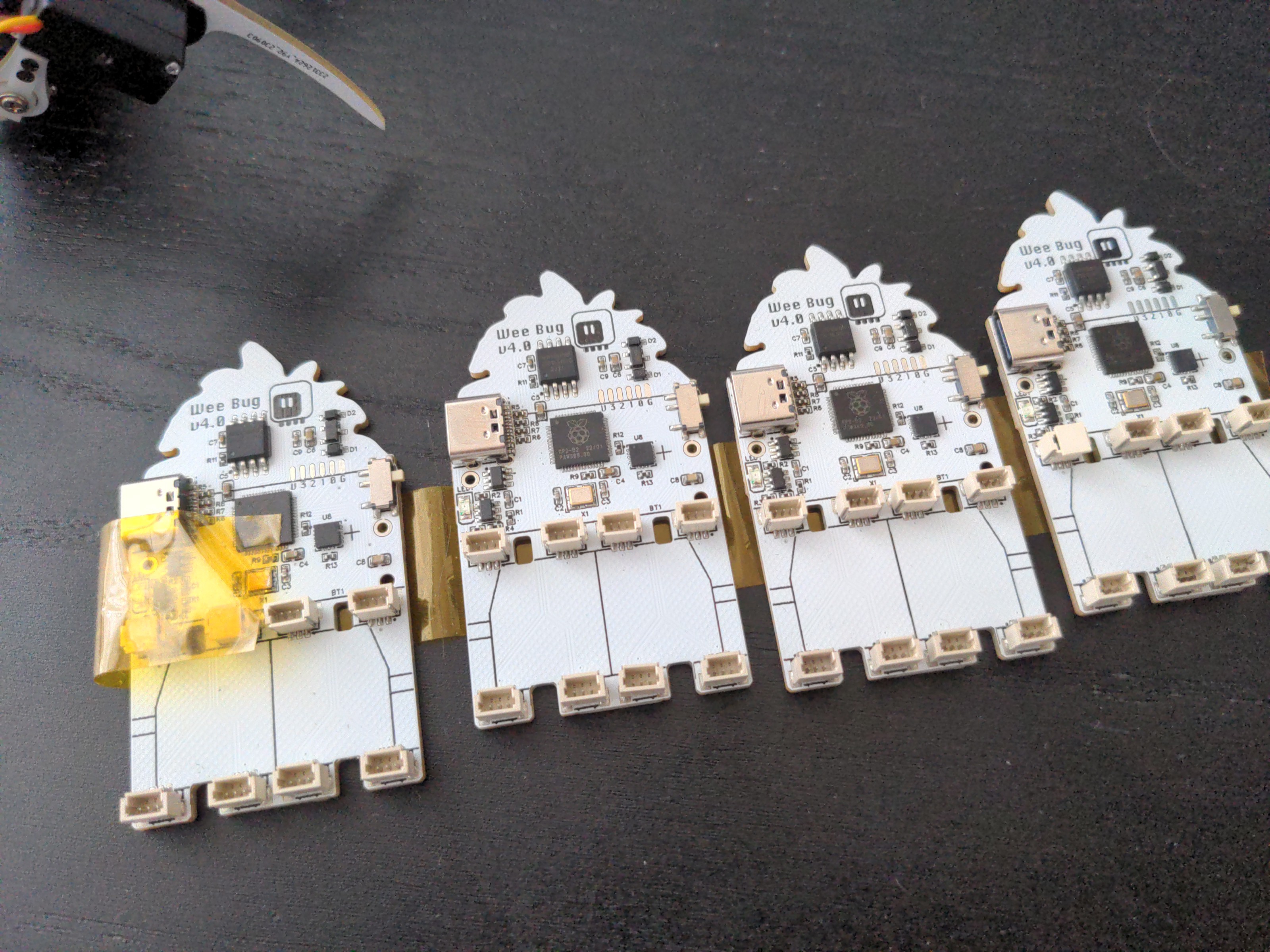
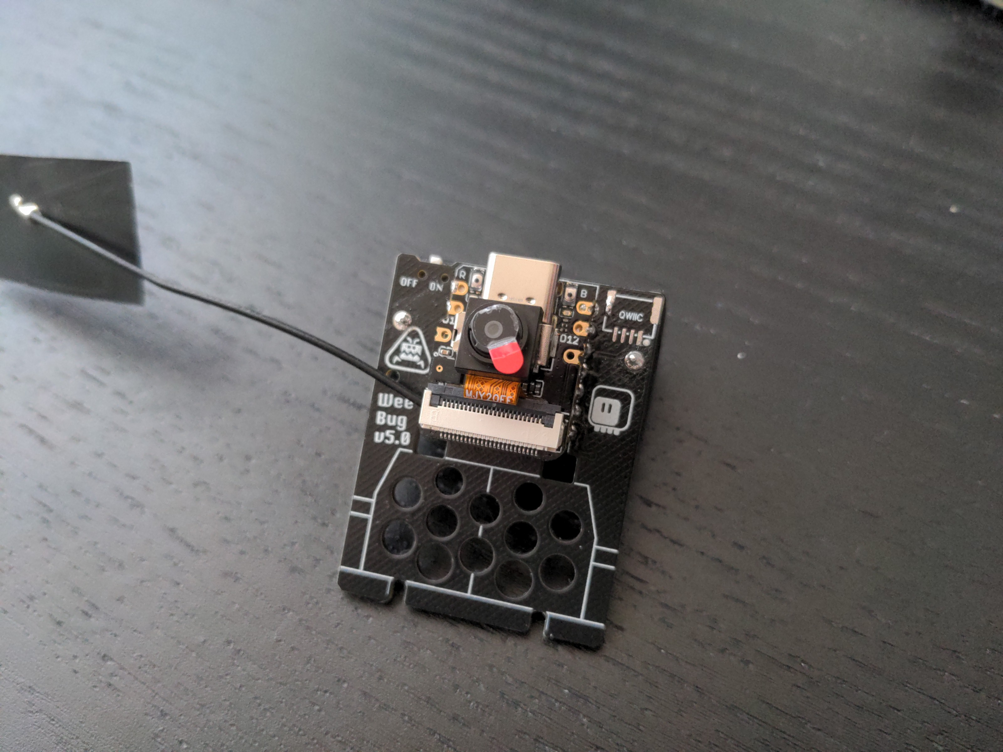
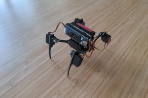
So I went ahead and started to design a Fluffbug, but with everything smaller.

  • Designs Published

    deʃhipu3 days ago 0 comments

    I have been putting off publishing the design files and code, hoping that I can clean them up a little bit first, but who am I kidding? If I don't publish them as they are, they are probably never going to be public. So I put them on github, you can find the link to the project repository on the left side of the hackaday.io project page.

    I will keep adding to the documentation, right now it's just the PCB schematic and designs, and the basic walking code. That should be enough for experienced tinkerers, but it could be much better, and I hope to make it better over time.

  • Thermal Camera

    deʃhipu03/19/2024 at 22:16 0 comments

    There is a header with the 3.3V power, I2C and INT pins broken out just above the servos on the Wee Bug (and other of my robots as well), because I was planning on plugging a time-of-flight distance sensor module in there. Turns out that a lot of different sensor modules are compatible with pretty much the same pinout, so you can use them in that place. So far I tried a gesture sensor and a TV remote IR sensor (that one is not a module, just a part plugged directly into the power and INT holes). But I noticed that the AMG888 thermal camera module also has the same pinout.

    So when I assembled a new #Moo Bug using a pi pico clone board with a built-in display, I decided to give it a try:

    Turns out that there is already a driver library for that sensor in CircuitPython, so my code was very simple:

    import time
    import busio
    import board
    import adafruit_amg88xx
    import displayio
    import rainbowio
    
    
    i2c = busio.I2C(board.GP5, board.GP4)
    amg = adafruit_amg88xx.AMG88XX(i2c)
    
    bitmap = displayio.Bitmap(8, 8, 256)
    palette = displayio.Palette(256)
    sprite = displayio.TileGrid(bitmap, pixel_shader=palette)
    board.DISPLAY.root_group = displayio.Group(scale=8)
    board.DISPLAY.root_group.append(sprite)
    board.DISPLAY.brightness = 0.01
    
    for i in range(256):
        palette[i] = rainbowio.colorwheel(255 - i)
    
    while True:
        for y, row in enumerate(amg.pixels):
            for x, temp in enumerate(row):
                c = min(255, max(0, int((temp - 20) * 30)))
                bitmap[x,y] = c
        time.sleep(0.1)
    

    Now I'm thinking about what kind of behavior I could code using that camera. And no, no heat-seeking missiles. 

  • Wee Display

    deʃhipu12/15/2023 at 17:52 0 comments

    A while ago I made a display shield (mask?) for the Wee Bug, but because it needs additional pins to talk to the microcontroller, it only works with the Waveshare Mini boards, and not the Xiao or QtPy boards, that don't have those extra pins. But then I found this tiny 0.66" OLED screen in my drawer, and thought "wait a minute, this display can use I2C for communication, and I already have an I2C bus for the accelerometer on the robot, so it would need no extra pins". All I need is a breakout board for it. Oh, and the tiny little issue of the reset circuit.

    What reset circuit, you ask? Well, I happen to know from experience, that those display will not work correctly when you just switch them on and start sending them data. They need to be restarted, physically, with the RST pin, a short moment after being powered on. I'm not entirely sure why, and why this isn't built into the chip's initialization, but that's how it is. If you don't do that restart, they will just keep displaying random pixels, ignoring any update commands.

    Normally I solve this in software. I have a GPIO pin connected to RST, and I wiggle it as a part of the display initialization. Easy enough. But in this case I don't have an extra pin to spare. So I need something else to wiggle the pin for me. A reset circuit.

    As always, as the first thing I went to Adafruit's excellent documentation, and looked at the schematics of their own display modules using similar displays. Sure enough, they had their reset circuits on them, in the form of an APX803L40 chip. Neat, just a single chip doing what I wanted, and I was afraid I would have to muck about with transistors and capacitors and resistors and diodes and who knows what else. The only problem is that the schematic didn't specify what threshold voltage should the chip have, so I ordered the 3.3V (because that's the voltage I will use to power the display) and 2.5V (because that's the 2/3 of the final voltage) versions. Then I quickly made a PCB and since it was so small, ordered it from OSHPark.

    When it arrived a few weeks later (free shipping from US is slooooow), I quickly soldered it up and tested. I immediately realized that I forgot to add the pull-up resistors on the I2C bus, but that's fine since the robot already has them, for the accelerometer. But even with those, it didn't show up on the I2C bus scans. What's wrong?

    At the time I was quite sick, and I didn't have the energy for too much experimenting. I just verified that it still didn't show up when I replaced the reset chip with a pull-up resistor, but didn't pursue it further. It went into a drawer.

    This week I felt better, and I decided to give it another look. I went over the schematic and compared it with examples of modules I found online. One difference between my schematic and the Adafruit one is that I didn't break out the RST pin, and I didn't include the pull-up resistor they have on it. A quick bodge job to add that resistor didn't help. Hmm. Another difference is that I didn't ground the unused pins. But the datasheet didn't say they have to be grounded... I tried another bodge to ground all those pins, and still nothing.

    What else could be wrong? I still suspected the reset circuit, so I desoldered the reset chip, and put a pull-up resistor in its place. And suddenly it showed up on the I2C scan! Turns out I need both the CE pin pulled low, and the RST pulled high. Of course the display wouldn't work like that, since it didn't get its reset after power up. So I once more put the reset chip in there, *and* added the pull-up resistor, while *at the same time* having CE connected to GND. That was it, that made it all work.

    It certainly took me more time than it should, but I have an animated eye working on the robot now.

  • 1mm and 1.25mm Versions

    deʃhipu12/12/2023 at 17:29 0 comments

    The 2g servos I'm using for weebug come in three different connectors: the traditional 2.54mm pitch servo plug, a 1.25mm pitch jst plug, and a 1mm pitch plug. I think the traditional plug is way too big for this kind of robot, so that leaves us with two versions: the 1.25mm and 1mm. I started with the bigger one initially, because that's what I had in my drawer, and I used through-hole sockets for them for the same reason. But when I later wanted to switch to SMD sockets, I found that all 1.25mm socket are for some reason unreasonably large, with big additional structural elements added on both sides. I switched to 1mm sockets because they were tiny in comparison. So all recent versions of the weebug use the 1mm sockets.

    I still had two early versions using the 1.25mm servos, and I wanted to upgrade them to the newer PCB. So I did a quick replacement to the through-hole sockets in the design, nudged aside some of the traces that got in the way on the back side, and added a footprint for the smaller battery holder, so that I can use either one. Oh, and I ordered it with yellow soldermask and black silkscreen, so that the danger stripes look how they should:

    I transplanted the legs from one of the old bots, and it works. I just have to update the code to account for the change of which servo goes to which pin.

    In other news, I'm still investigating servo power issues. No definitive conclusions yet, but I'm leaning towards ditching the boost converter and putting the servos back on direct battery power. Together with using reasonable quality of batteries, that should help.

  • Not All Batteries are Created Equal

    deʃhipu12/01/2023 at 18:08 0 comments

    With the new PCB in version 6.0 I switched to the bigger 16340 battery that I originally used in #Fluffbug, thinking that the extra weight is not so great, and extra capacity will be useful. Also those batteries are much easier to find, since they are commonly used in vapers. And incidentally, with version 6.0 I started to have problems with power. The robot would work on a fully charged battery for maybe half a minute, and then the servos would get all shaky, and soon the protection circuit would kick in and shut the power down.

    I initially thought the shaky servos are because those small 2g servos come in two versions: 3.7V and 5V, and maybe I got the 5V ones this time. So I made a PCB version 6.1 where I added a boost converter to give the servos consistent 5V voltage. It didn't make any difference, though, the servos were still shaky. I tried added capacitors everywhere I could, but that didn't solve the issue.

    On a hunch, I made a professional adapter out of a paperclip, and inserted the previous 14250 battery. Suddenly all the power problems went away, the servos are no longer shaky (both with the boost converter and without). Interesting. So I went looking for a 16340 battery from a different batch, and lo and behold, the power problems are also gone. It was the battery all along.

    Turns out that you really have to be careful where you get your batteries, because they differ not only in capacity (by the way, don't believe in what they print on them, a battery with that capacity would need to be four times bigger with this chemistry), but also in their C-rating, which is basically how much current you can draw from it at once.

    You need to somehow find a "reputable" source for your batteries, which is a bit of a problem, because obviously this is a lemon market. Out of curiosity, I also tried a battery removed from a vaper that I found on a sidewalk. Turns out that it performs really well, despite being a no-name thing. I guess the manufacturer of those devices found a trusted source.

    So if you really want to save on the battery, check your sidewalk for a free one. You will also save the environment from being poisoned with toxic lithium.

  • Add Some Fluff

    deʃhipu10/24/2023 at 14:33 0 comments

    I intentionally make my robots minimal in terms of additional aesthetics, to make them easier to make and customize for others. But sometimes you just want to have some fun, so when I saw this bunny-shaped ipods case, I knew what I need to do:

    It's just the right say to fit the Wee Bug's body inside, minus the battery. I just had to dremel two large holes in the bottom for the legs, and replace the battery holder with a more traditional pouch lipo battery.

    I also glued some small magnets to the lid and the case, to make the lid stay closed more firmly. As the microcontroller, this time I used a Waveshare RP2040 Zero board, so I have a bunch of extra pins at the bottom, that are not used by the servos. I added some wires to them, to potentially make use of them later. I think I will need at least one pin for an infrared remote control sensor, because that board doesn't have wifi for control. I have some sensors that look like small black eyes, so that should work pretty well. In the mean time I used a single goggly eye, just for some added character.

    While obviously this is a custom job, I think that ipod cases are a standardized and common enough thing for other people to be able to do similar things with them. It's a bit of shame that I couldn't keep the standard and replaceable battery.

  • Balancing

    deʃhipu10/14/2023 at 19:10 0 comments

    I had some time for coding at the hackerspace this week, so I wrote simple code for balancing to test the accelerometer. It goes something like this:

    import robot
    import time
    import lis3dh
    import busio
    import board
    
    
    i2c = busio.I2C(sda=board.D4, scl=board.D5, frequency=600000)
    accel = lis3dh.LIS3DH(i2c)
    height=20
    
    tilt = 0
    while True:
        x, y, z = accel.get()
        if x > 500:
            tilt = min(tilt + 20, tilt + 1)
        if x < -500:
            tilt = max(tilt - 20, tilt - 1)
        for leg in robot.LEGS:
            if leg.left:
                leg.move(0, height - tilt)
            else:
                leg.move(0, height + tilt)
        time.sleep(0.05)

    Even for simple code like this, the effect is pretty cool:

     Of course to make it useful, it has to also work in the other axis, and be integrated with the walking algorithm and others. I have some ideas about how to do it, though, so stay tuned.

  • A Display

    deʃhipu10/13/2023 at 20:47 0 comments

    There are many different microcontroller boards that you can use with Wee Bug, from the Seeedstudio Xaio, through Adafruit QtPy, to Waveshare Zero boards. They all have the power pins in the same places (sometimes mirrored), and the GPIO pins are flexible enough to be used in the roles they need in the robot. But the Zero is particularly interesting, because they have four additional pins at the bottom of the board, that could be used by an additional board connected on top. Like, for instance, a display. It so happens I was working on getting one display to work, and I needed to make a breakout board for it, so I thought why not, and made it a shield, or maybe a "face shield", for the Wee Bug.

    And since the other display I was recently playing with has the exact same footprint, I made the breakout in a shape that fits both of them. At a whim, I also added a footprint for the 1.8" ST7735 display on the other side, just because I could.

    Of course the next step is to make it display something interesting. I already experimented with eyes, and the closeup of a single monstrous eye that Adafruit demos do is a bit too monstrous to my tastes, so for now I went with the GIF animation I made for the #Astro-chan Badge. I plant to eventually re-draw the same character I used on the silkscreen on earlier prototypes, and animate it to make it look like it's controlling the robot from the inside, but of course that is much more work than it seems, so it will take a while.

    The practical advantage of having a display on a CircuitPython-programmed robot is the fact that you no longer need to explain how to connect to the USB console, so you can see error messages. People can just read the errors from the screen.

  • Version 6.0

    deʃhipu09/30/2023 at 21:10 0 comments

    That last prototype I mentioned in the last log finally arrived on Friday:

    And I got it all assembled and programmed today:

    I also have the camera and the accelerometer working, though I don't really do anything interesting with them yet. You can see that I re-used the servos that already had the cables shortened to the right lengths, so as to not be an unholy mess of wires, but if I didn't, I could tuck all the extra cables under the microcontroller board, plenty of space there. There is also a WiFi antenna hidden under the battery – the Xiao ESP32-S3 Sense board I used here comes with an external antenna.

    The bigger battery and longer legs work fine – the servos are easily strong enough to take it, and the hind legs don't need to move so high that they would collide with the battery.

    I'm really happy with it, and now I should be focusing on the software side of things, making the movements smoother, making use of that camera and accelerometer, and generally teaching it more tricks.

    I also want to try it with boards that are more or less compatible with Xiao, like the Adafruit QtPy, or Waveshare Zero. The latter will stick out a bit, and will need to be inserted up-side-down, but the extra pins could be useful for a display shield.

  • A String of Prototypes

    deʃhipu09/20/2023 at 17:23 0 comments

    The first Weebug was just a quick hack to see if it will work. It turned out to work even better than Fluffbug, so I made a second one, this time trying to make it look cool, and cleaning up the design. But if I want to do workshops with this eventually, I need to make it easily manufacturable and as easy to assemble as possible. So I made another prototype, with the same PCB art, but with an RP2040 chip instead of the unobtainium SAMD21.

    That was also a test for the JLCPCB assembly services, a test of the new leg design, and a test of the 1mm servo plugs, that are physically much smaller than the 1.2mm ones, at least in the SMD version. The results are... mixed. The assembly service works as advertised and is very nice, but now I have five assembled boards I paid for that I have no use for – I will explain why shortly. I also had to pay the customs duty on the package, because with shipping it went over the threshold, so it got more expensive than I anticipated. I think that in the future I will prefer assembling the prototypes by hand myself, even if that means I have to make a separate order at LCSC for the parts.

    What didn't work so great are the servo sockets, and that's mostly because of my own mistakes. First of all, I placed them too close to the servo mounting holes. There is enough clearance for the servos themselves, but not for the head of the screw that holds them in place. I had to break out my hot air gun and move the sockets slightly in on their footprints to make everything fit. Of course I can't expect anyone else building the robot to do that, so I can't give out or sell those boards. The second mistake is even more stupid. I swapped the signal and ground pins on the sockets. I was able to test the robot by carefully swapping those wires on the servos (the contacts in the plug are easy to remove and swap), but again, I can't expect anyone else to do that.

    And of course there is still the continuing problem of cable management, for which the only solution I found so far is to open each servo, desolder the wires, cut them to the right size from that side, and solder them back and reassemble each servo. The result is very clean and aesthetically pleasing, but it's a bit too much fiddly work for a workshop, and I can't do it for every servo in every kit.

    So that's a partial success. I definitely learned a lot, but there is some unnecessary waste in there...

    I also decided that putting a bare chip on my boards doesn't always make sense. It's great when I need a lot of GPIOs, for example for a display or camera, but otherwise using a development board is both less work, and, in at least in case of the rp2040 and esp32 boards, cheaper – when I'm not assembling them myself, anyways.

    In the mean time, I got my hands on the Seeedstudio Xiao ESP32-S3 Sense devboard, and I was greatly impressed. Not only is it blazing fast and has loads of memory and flash, but it even comes with a tiny little camera and microphone module, perfect for a robot like this. And it's still in the Xiao form factor. So I made another prototype, this time specifically for this Xiao board:

    It even includes battery recharging chip, though to use it you have to solder to some pads on the back of the board. That is what pushed me towards soldering the Xiao board directly to the PCB instead of using a socket. In hindsight, I think it was a mistake. For convenience, I made through-hole contacts on the back where those pads are, so they are easy to solder this way, but it would be much nicer to have the devboard removable. Oh, and I got the servo sockets right this time: the signals are correct, and I moved them out of the way of the screws. I had to move some electronic components under the battery holder, which made it later very annoying to debug my battery problems, but oh well.

    But I didn't avoid mistakes completely this time either. The DW07D chip I use for protecting the battery didn't work correctly this time, even though it worked in all the previous...

    Read more »

View all 17 project logs

Enjoy this project?

Share

Discussions

Similar Projects

Does this project spark your interest?

Become a member to follow this project and never miss any updates