 Tobias
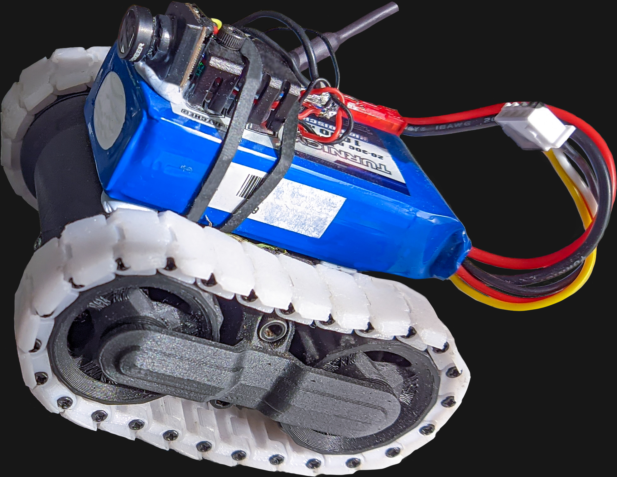
Introduction
This is a project that I designed like a year ago, and only got to building more recently. Too many RC tanks I see online either use tiny N20 gearmotors, or sh***y plastic continuous servo motors. SLOW! LAME! The aim of this design is to make an RC tank that is small, but also has POWAH. To do this, I squished 25mm diameter brushed gearmotors into the smallest, most sturdy body I could. I also designed some 3D printable tank treads.
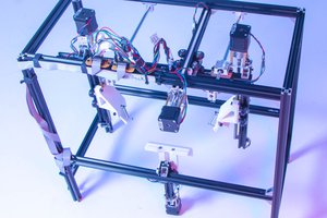
3D design
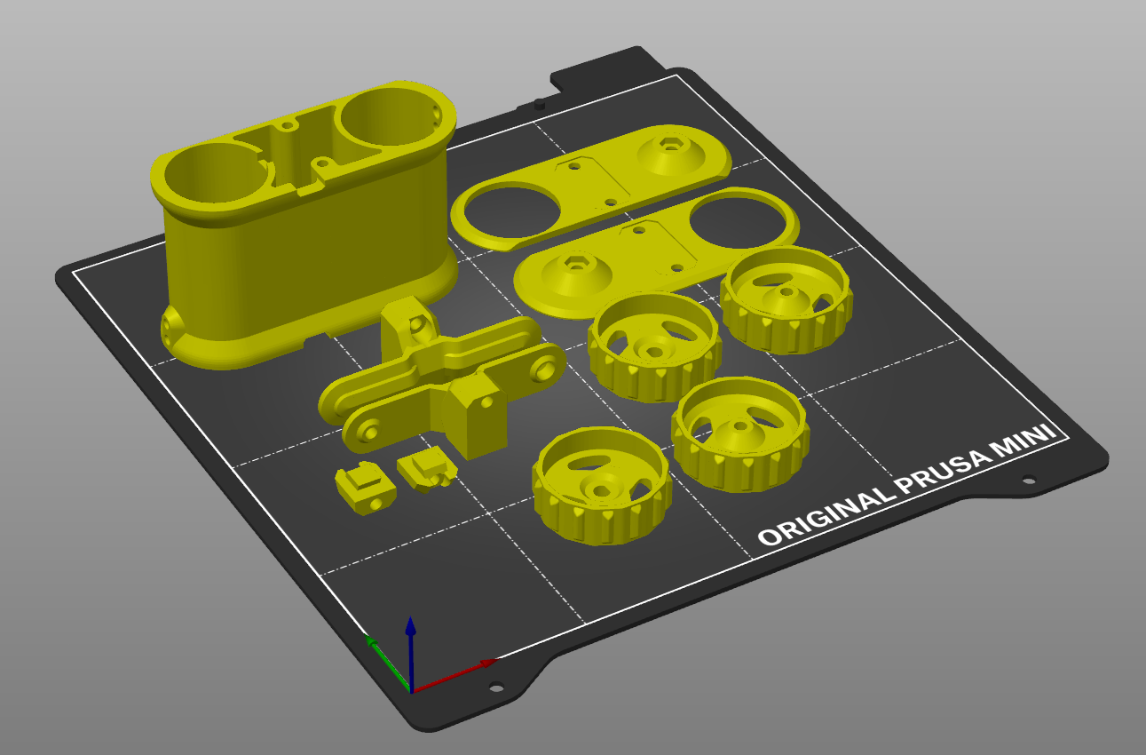
This tank was designed in Autodesk Fusion 360, with a focus on maximum compactness and structural integrity, whilst hopefully looking somewhat sleek. I probably spent too long on this, but I did enjoyed optimising each part of the design!
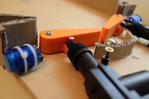
Treads
I wanted to design some miniature treads that would be strong and flexible. The process of designing these took the longest due to the iteration and refinement that was required to get these right.
This is one of my early test prints (deliberately broken to test strength):
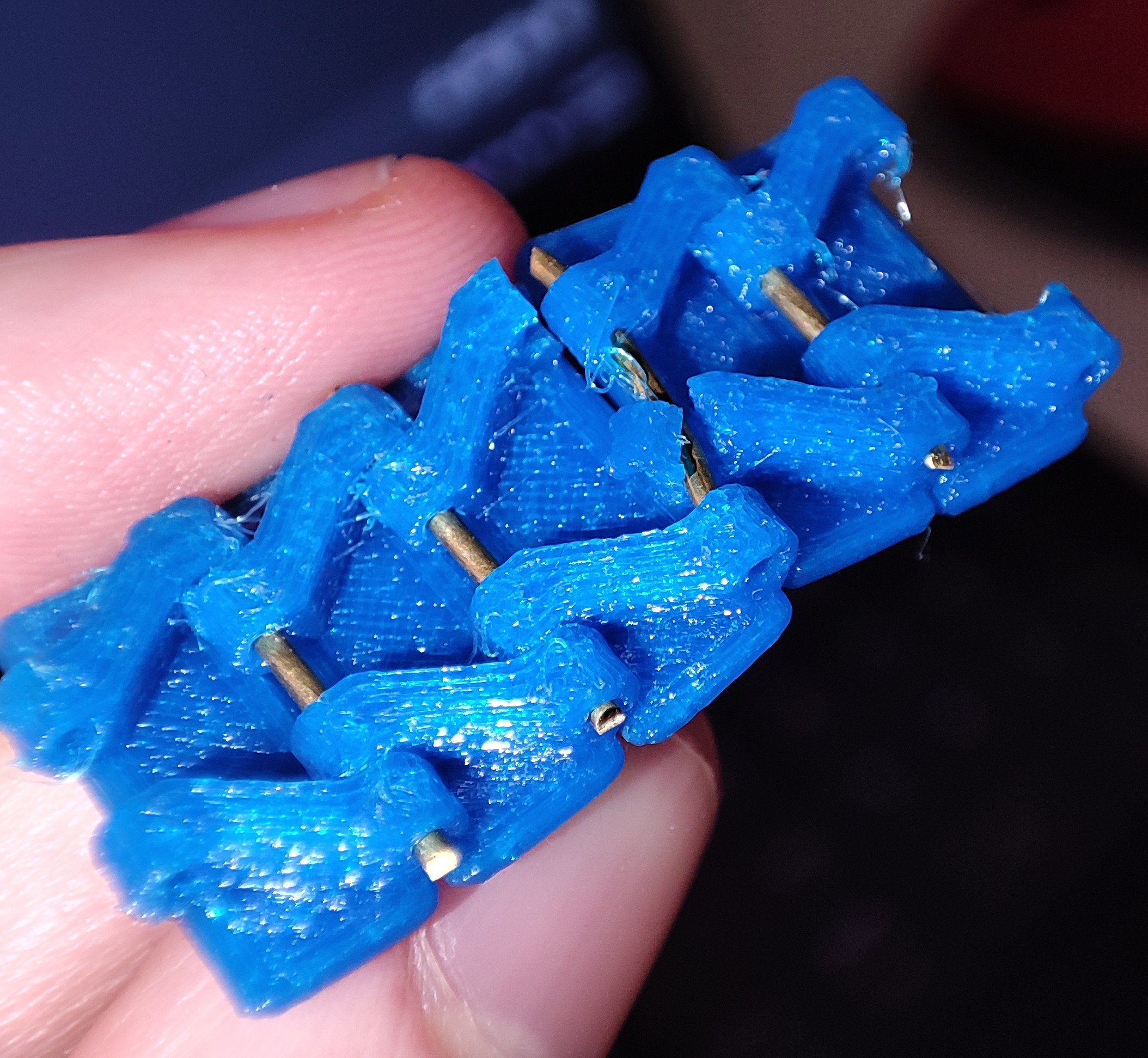
The design of these early treads was simpler, and I was initially trying to use brass rods. Unfortunately using rods instead of screws doesn't work in such small treads, as they are prone to slipping out, plus they can bend under load.
I also tried using flexible TPU material to print the whole tread in a single piece, but I dismissed this quickly because the TPU treads were pretty stiff, and just not as cool as a tread made of discrete segments!
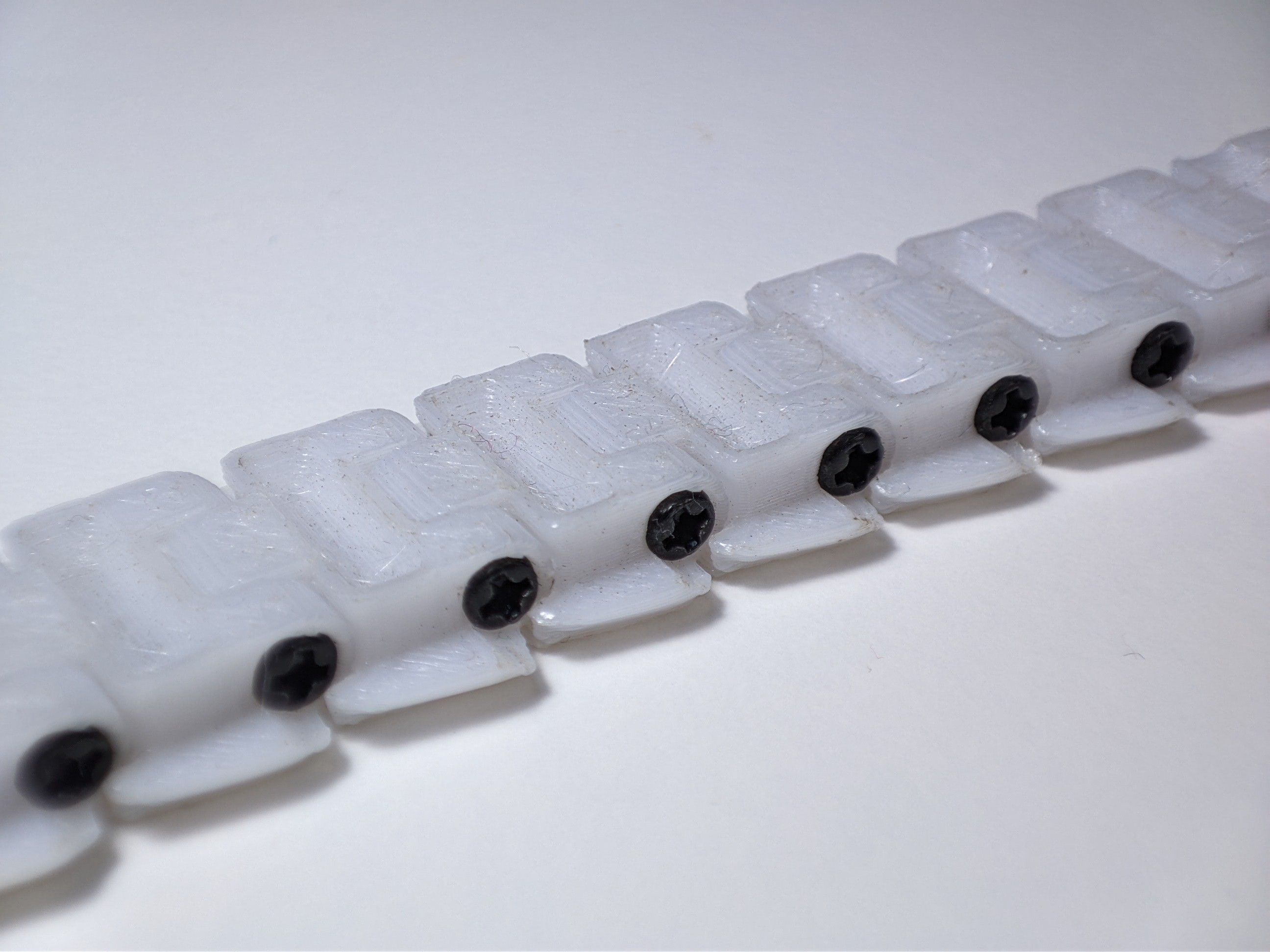
Below is the final tread design. The treads are linked together with course-threaded M1.7 screws, and have grooves that match the teeth on the wheels. I maximised the material around the hinges for the sake of strength, and when printed out of PETG they have are plenty durable. I also gave them cool angular sides which gives the tank a +20% speed boost.
Body
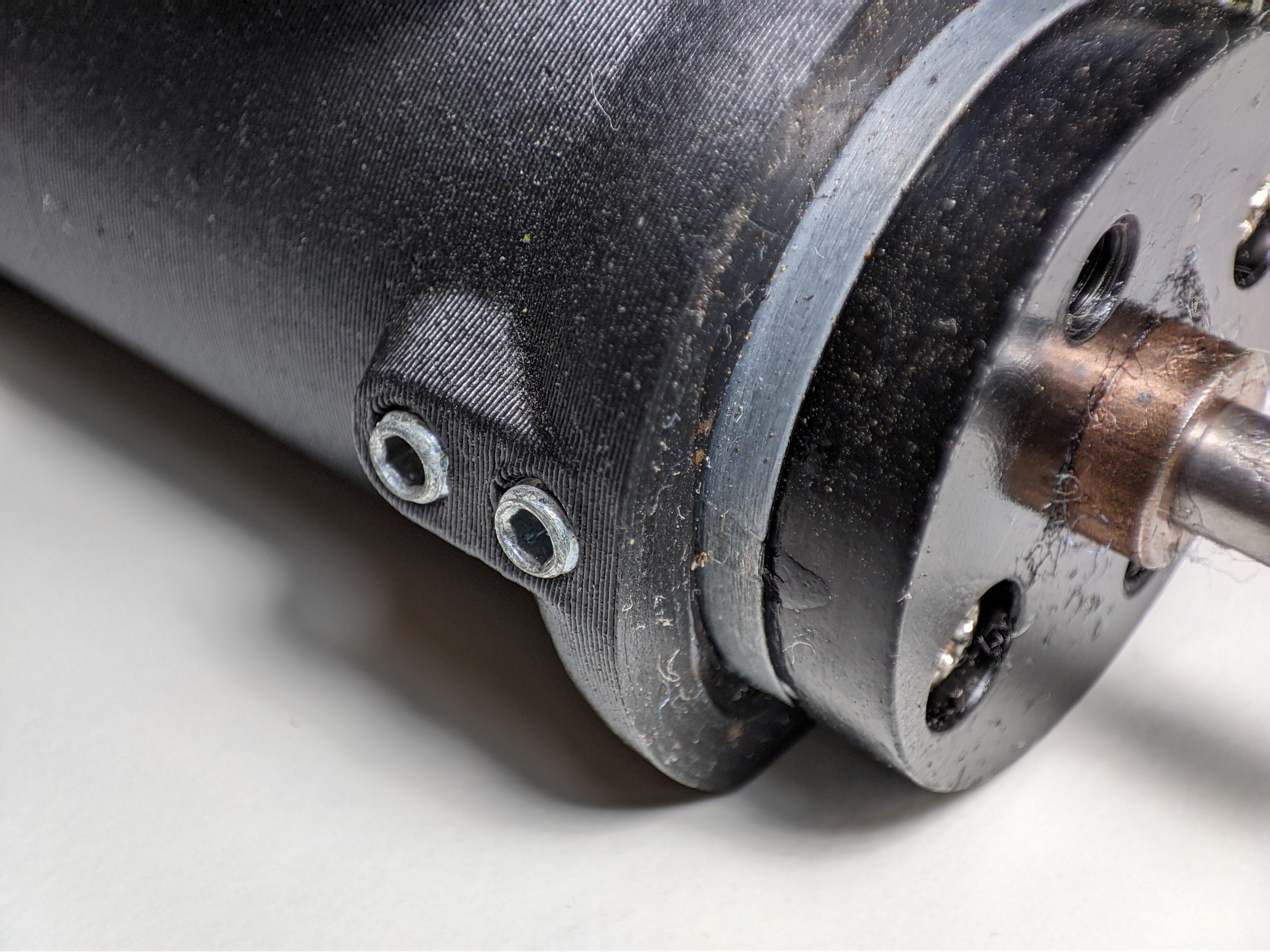
Below is a cross section showing how the space for each component is arranged. As you can see, the motors take up most of the area and extend into the wheels! Additionally, the motor shaft and idler screw tips would stick out of the sides if not for the part that covers and holds them in place. Two grub screws hold each motor in place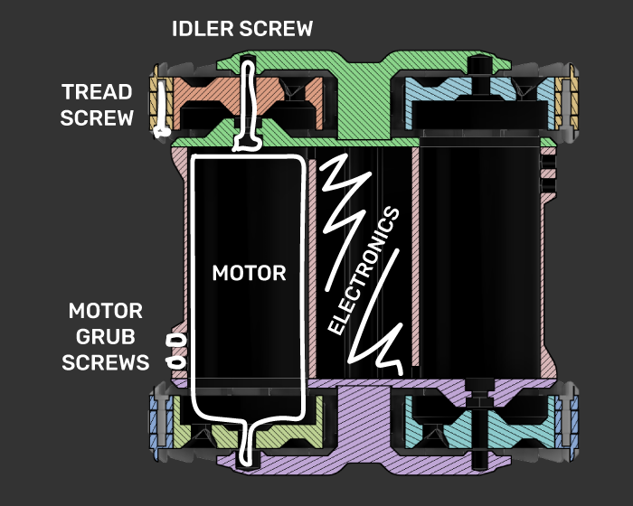
Design done!
Hardware
These are the motors I bought on Aliexpress:
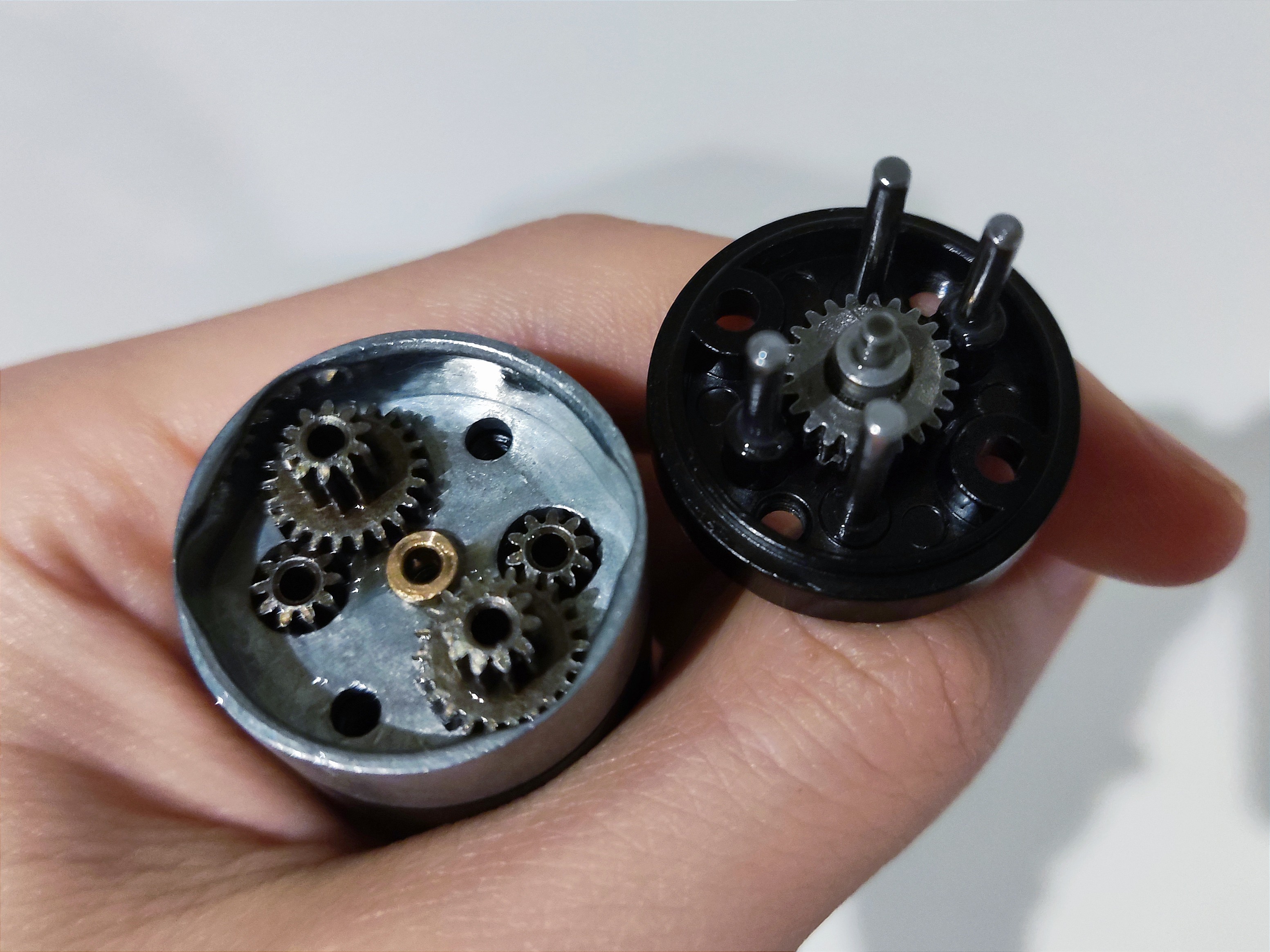

These are 25mm diameter 2083rpm brushed gearmotors. Brushed DC motors are hardly the apex of power systems, but a brushless system would be WAY more expensive, so I'm using these for now. Plus, they have more than enough power for the size of the tank.
Electronics
FPV related
I decided to use standard RC/FPV devices for the remote control and video transmission.
I was initially planning on using nRF24L01 transceivers, and making a custom-modelled 3D-printed hand-wired Arduino-powered controller, as I have seen some on the internet do. However, even after buying most of the the parts necessary for this, I considered the complexity that this would add, and decided against it. Instead I opted to purchase a proper FPV controller, which communicates over the amazing ELRS protocol. This allows me to use one of the tiny 1x1cm, SMD antenna receiver modules.
I also picked up a tiny FPV camera from Foxeer, and a tiny FPV analog video transmitter. I could have used an ESP-32 camera and stream the video over a web server or something, but again, this is much simpler.
Here is a family photo of the three aforementioned electronics next to an Aussie $2 coin:
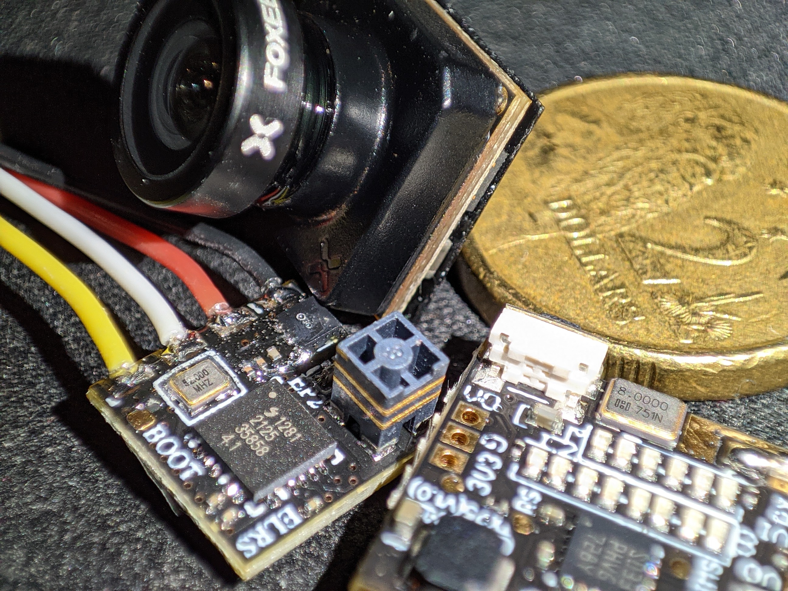 Awww, so cute!
The rest of the electronics
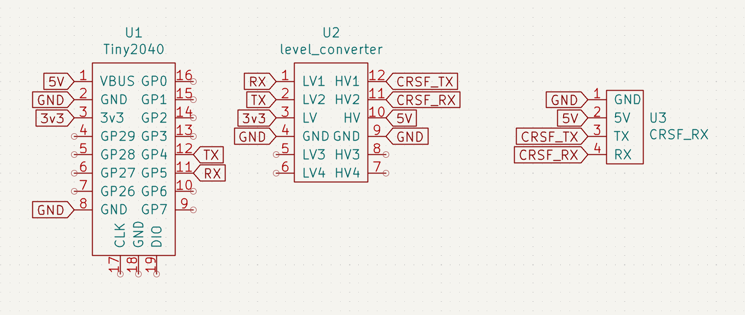
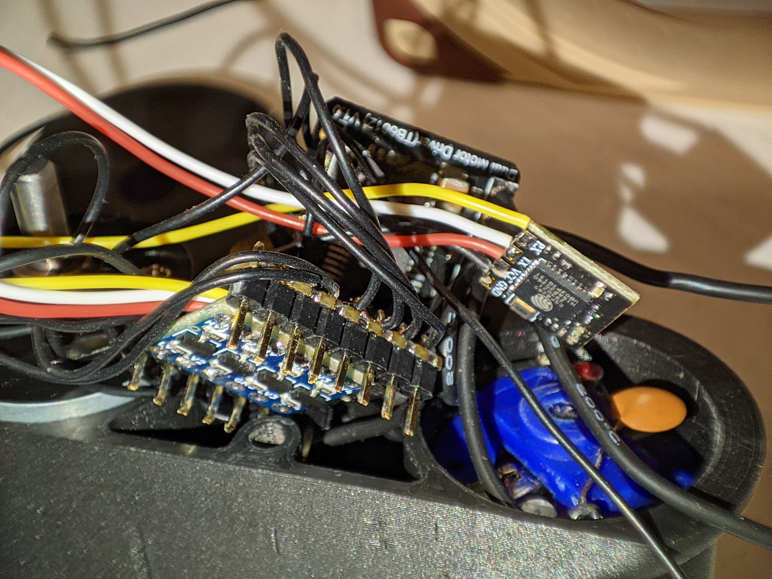
Here is where I transition from the RC/FPV ecosystem into just normal electronics. In my setup, I have a motor driver that is designed to be controlled by a microcontroller (and not by an RC system servo signal), so I put my smallest board to the task:
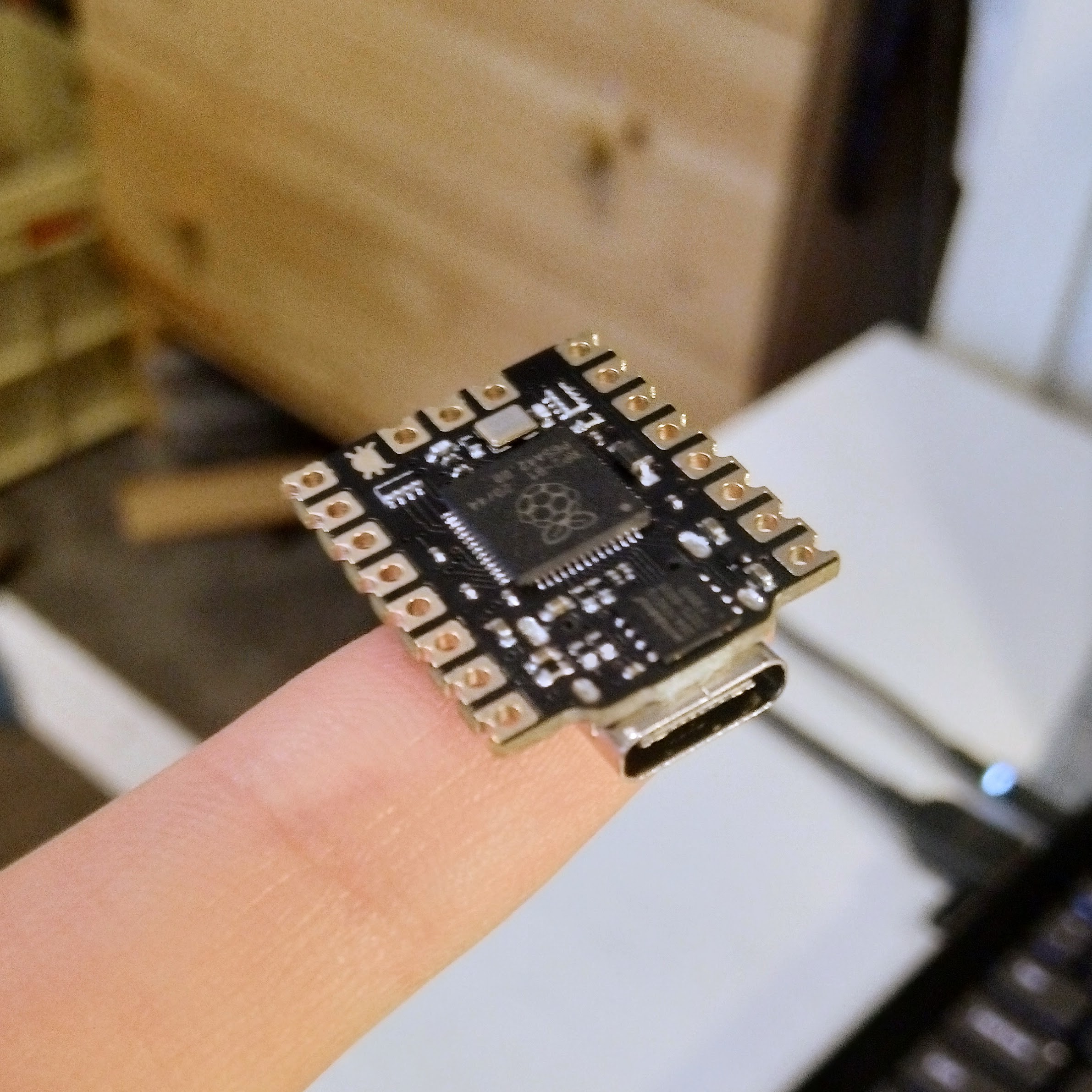
Again, so cute! This Pimoroni Tiny 2040 has an RP2040 aboard. It does the job great, but I won't actually be using much of its' potential. I chose this one which I already had, but any microcontroller that fits, and runs Arduino code, should work! (I think)
The Tiny 2040...
Read more »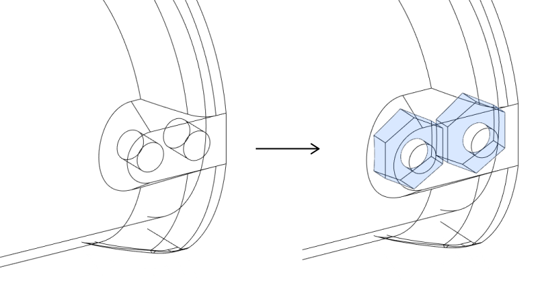


 Chris Mitchell
 Brian Brocken
 ProgressTH
About RPM: I bought 1200 and 400, just to be sure that the motor can turn the track. If that works well I'll swap out the motor for the faster ones.
Have you mentioned somewhere that the screws for the tracks need to be M1.7 (I found that somewhere) x 12 (I wasn't able to find that anywhere). (I bought 10, 12, 14 and 16 and 12 seems to be what it was made for.
I don't really have electronics yet. I might make a Pico W "shield" that has two motor drivers.