Close
0%
0%

Next Gen Interactive Dance Floor

Modular touch-sensitive LED dance floor

Similar projects worth following
I've gone back to the drawing board to make a better touch-sensitive, interactive, dance floor.

Follow along my journey to make this a reality.

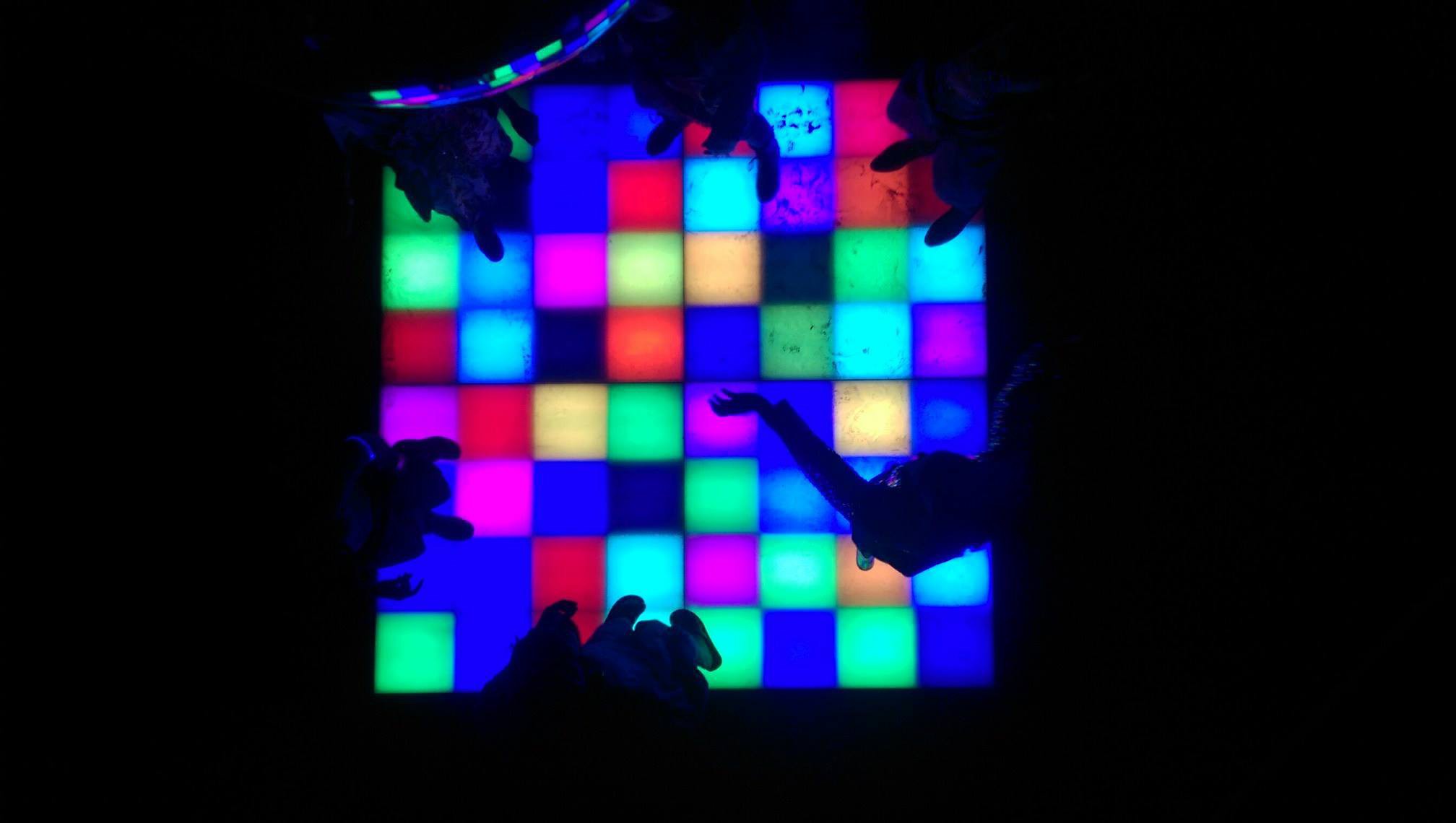
Back in 2016, I made the original interactive dance floor, and ever since then, I've wanted to rebuild it from scratch and make it better. 

Project goals:

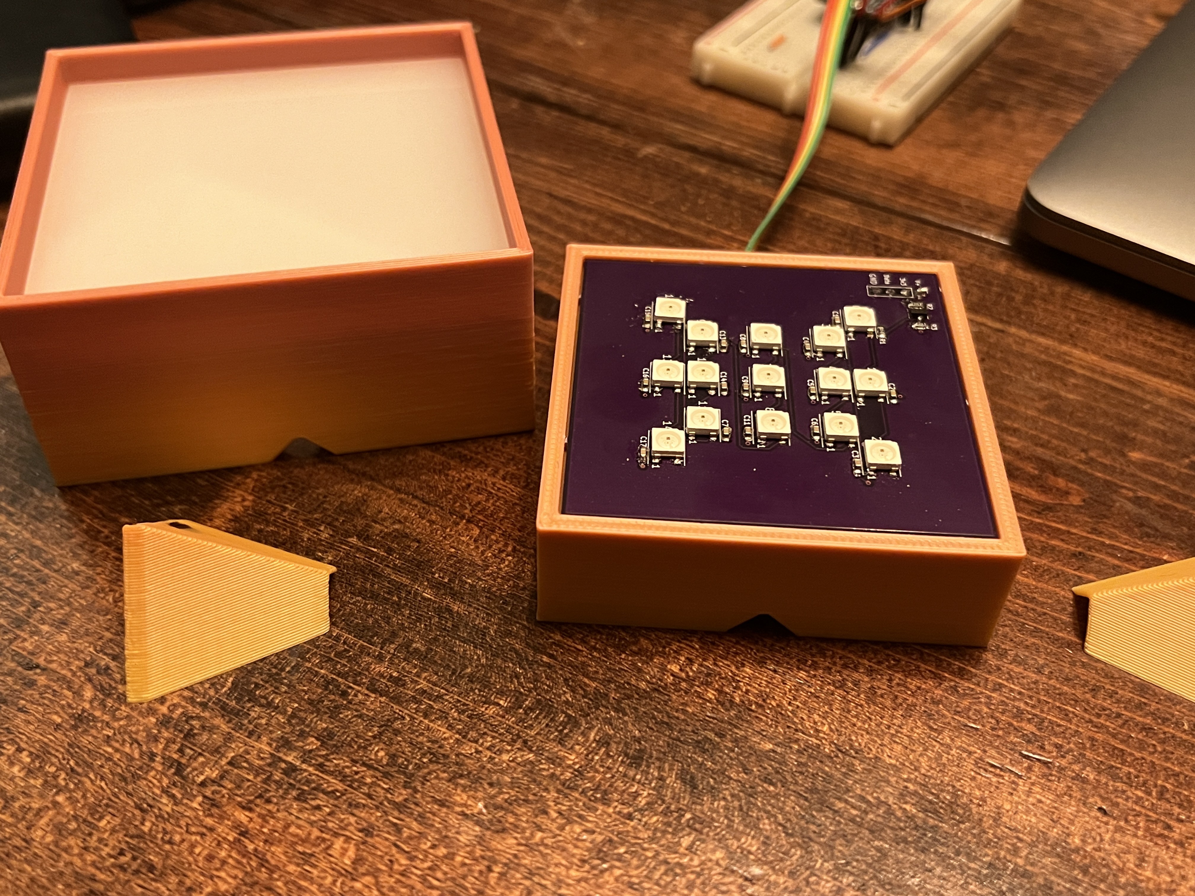
  • The floor will be constructed of small modular panels that snap together (~15" x 15") .
  • Each LED "pixel" on the floor will be between 1" to 2.5" squared.
  • The entire floor will be a giant capacitive touch screen.
  • Animation programming will be PixelBlaze compatible.

  • 1 × ESP32-C3-MINI

  • Determining diffusion distance

    Jeremy02/10/2023 at 06:37 0 comments

    To keep cost and weight down, it's essential to make the floor as compact as possible. However, LED diffusion is in direct competition with this goal.

    The surface of the dance floor will be 1/4" semi-opaque white acrylic. If the LEDs are right up against the bottom of the acrylic, the dance floor will be pretty thin, but very little diffusion will occur, and you'll see each LED as an RGB dot. So the LEDs will need to be at an undefined distance from the acrylic to optimize diffusion but reduce unnecessary height.

    To determine this distance, I 3D printed a jig and designed a PCB with an addressable LED grid that I could use to light different patterns.

    This was driven by a Thunderpack compact microcontroller.

    Setting distance

    The box with the acrylic fit over the PCB, and the half-pyramid pieces slid in either side to raise or lower the acrylic.

    LED Patterns

    Here are the LED & color patterns I was testing. The brightness is kept at 50% for each color -- if I optimized for 100%, the diffusion would look pretty bad at anything less than full brightness.

    Diffusion in action

    The video doesn't do it justice, but you can see how the diffusion changes as the height changes. 

    Results

    After several rounds of testing and two different LED grids, I found that the outer square pattern at a distance of 1/2" (13mm) from the acrylic provides the best overall diffusion. This put's each floor tile at about 1" thick (1/4" acrylic + 1/2" diffusion gap + 1/4" floor tile base). 

    For comparison, this is a pretty big improvement over the original dance floor which was 4" thick.

  • What's my plan

    Jeremy01/08/2023 at 01:51 0 comments

    The goal is to have an interactive dance floor made of modular tiles with LEDs divided into ~2.5" touch-sensitive cells. But there's so much to it.

    I think the best way to describe the current plan is to talk about the things I plan to do differently from the original dance floor.

    The original dance floor

    Touch Sensors

    This floor will use capacitive touch sensors under each LED cell in order to make it interactive. Using capacitive sensors means fewer moving parts that might wear out and allows each LED cell to sense even a light movement over it.

    I'll be using similar touch-sensor technology as the original floor. The sensor itself will either use ITO conductive plastic under the floor surface or a loop of wire. I'm still figuring this part out.

    Higher Resolution

    On the original floor, each LED cell was roughly 12" x 12". An "LED cell" is an area of the floor that acts as a single light-up square. The size of the original cells worked well but limited the kind of animations that could be done.

    The new floor will have much smaller cells at about 2.5" x 2.5". This should allow for much higher-resolution animations.

    Modular Floor Panels

    The last floor was made of heavy 3' x 3' sections and a large fixed-size frame to hold the entire floor together. It was all very cumbersome and required a pretty big truck to transport.

    This floor will be made up of individual floor tiles that are each roughly 12" x 12". Each tile will have 16 LED cells in it. Each tile will be built on top of interlocking dance floor tiles. This should remove the need for an exterior frame and make setting up and tearing down the floor much faster. 

    Communication Protocol

    The original floor used an RS485 bus that allowed for a pretty robust and fast way to communicate with all the nodes (see the Disco Bus Multidrop Communication Protocol). It worked pretty well, but was pretty limited in what it could do and required a considerable amount of time to build and debug.

    The new floor will be "wireless" and each floor panel will have a single ESP32-C3 module that will communicate to a central hub. The potential issue here is overloading the wifi router if too many floor panels try to communicate at the same time. This shouldn't be too much of an issue, since there will likely be, at most, 64-floor panels (for an 8' x 8' floor). If the network starts getting overloaded, the panels can limit how frequently they make requests to the hub. I'm also planning to use the lightweight UDP networking protocol, where possible, and keep the data sent in each request to a minimum.

    Automatic Layout Discovery

    Ideally, when the floor is turned on, it can automatically determine the floor layout and build a map of all the floor tiles in relation to each other. To do this, each floor tile will have a connection to its neighbors.

    There are a couple of ways we can map the floor:

    Mapping method 1 

    To detect neighboring tiles, the hub will ask a single floor tile to drive the wires between its neighbors to an active state. When neighboring floor tiles notice this wire go active, they'll report back to the hub which side became active. Now the hub knows who that tile's neighbors are. The hub will repeat this for each floor tile to generate a floor map.

    Mapping method 2

    Or, the wire between each tile will be connected to UARTs between tiles. During the addressing phase, each tile will announce its ID repeatedly. The neighboring tiles will receive these addresses and report back to the hub which tile is along which edge. After all the tiles report back, the hub should be able to generate a floor map.

    Whichever method, we'll need a way to wire one tile to the next. I'll likely use blade or compression connectors to make it easier/faster to connect the tiles together as the floor is assembled.

    Animation Library

    These days Pixelblaze is the leading LED animation hardware/API. Their underlying API...

    Read more »

View all 2 project logs

Enjoy this project?

Share

Discussions

Similar Projects

Does this project spark your interest?

Become a member to follow this project and never miss any updates