ElectroBoy
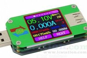
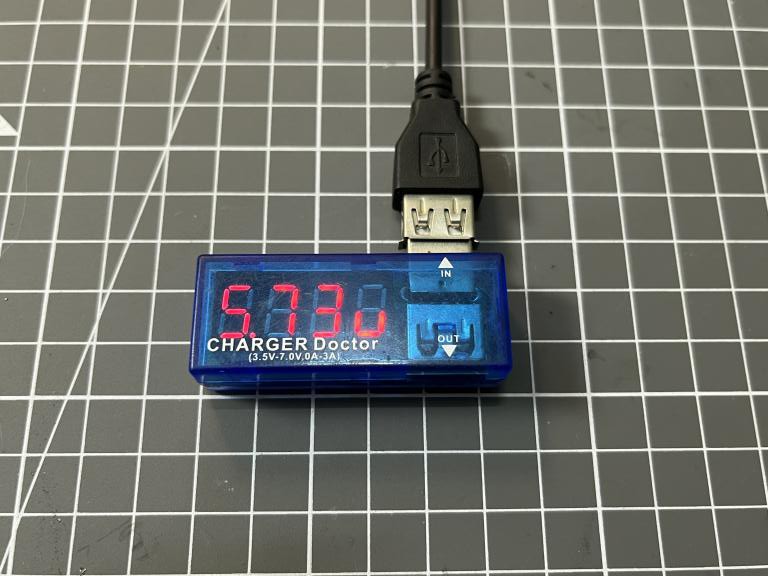
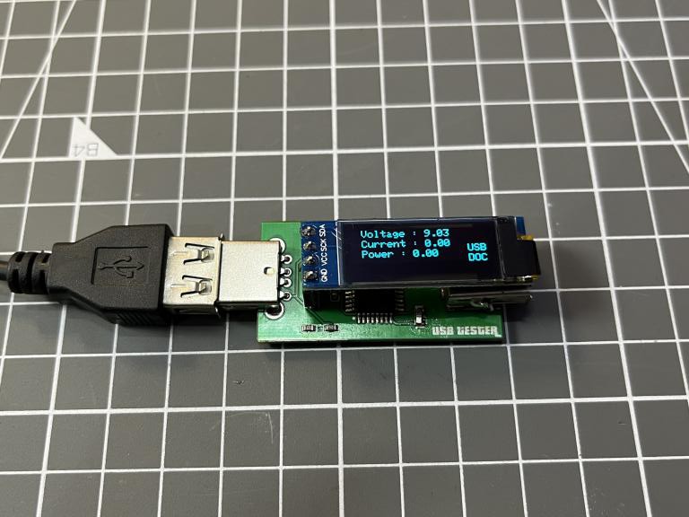
A lot of power meters available in market which delicately made to work with 5volt charger power. The maximum ratings of my commercial one is 7v at 2amps. Now I want to use this USB charger doctor with my fast charger but it is not compatible at all. That’s why designing of this DIY charger came into my mind. My fast charging adaptor goes upto a rating of 80watts. A voltage divider network is used to measure the voltage upto 20volts with a current rating of 5ampere. I want to display the real time readings of this USB doctor on a small display and I choose atmega328p as a microcontroller and SSD 1306 128x32 OLED display of it.
Voltage readings are direct measurable with 10-bit internal ADC of the microcontroller which gives a resolution of 15mV and I used dedicated ACS712 for the current measurements. Which is based on hall effect and using this current readings can be easily converted into respected voltages and then any variation in current produce variation in voltage (For 5v ACS take 2.5v as a reference). To know more about ACS712 and it’s different variants check the data sheet from here.
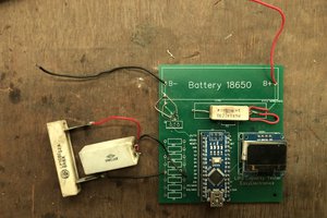
I prefer to make a PCB for this project because you can directly plug this into charger socket. Variation due to wires and tracks will be very less. I am using JLCPCB for the PCB prototypes, JLCPCB is China based PCB manufacturing company deals in a lot of PCB products including SMT assembly, precision PCB, stencil making and 3-D printing.
Components Required:
- Arduino nano or Atmega328p
- ACS712 5A version
- SSD1306 OLED 128x32 display
- 10k, 4.7k resistors
- 100nf and 10nf ceramic capacitors
- Ams1117 5v
- USB Type A connectors
- 16MHz crystal oscillator
- Custom PCB from JLCPCB
Circuit diagram:
I made this circuit using EasyEDA because it is very compatible to JLCPCB. I used a 5v linear step down convertor to power the microcontroller and other peripherals. rather connecting pin headers of Arduino Uno I designed a circuit which has same properties using the microcontroller IC and 16MHz crystal.
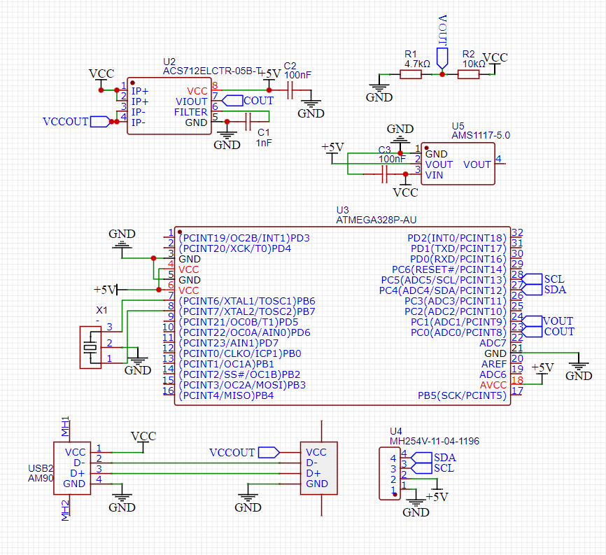
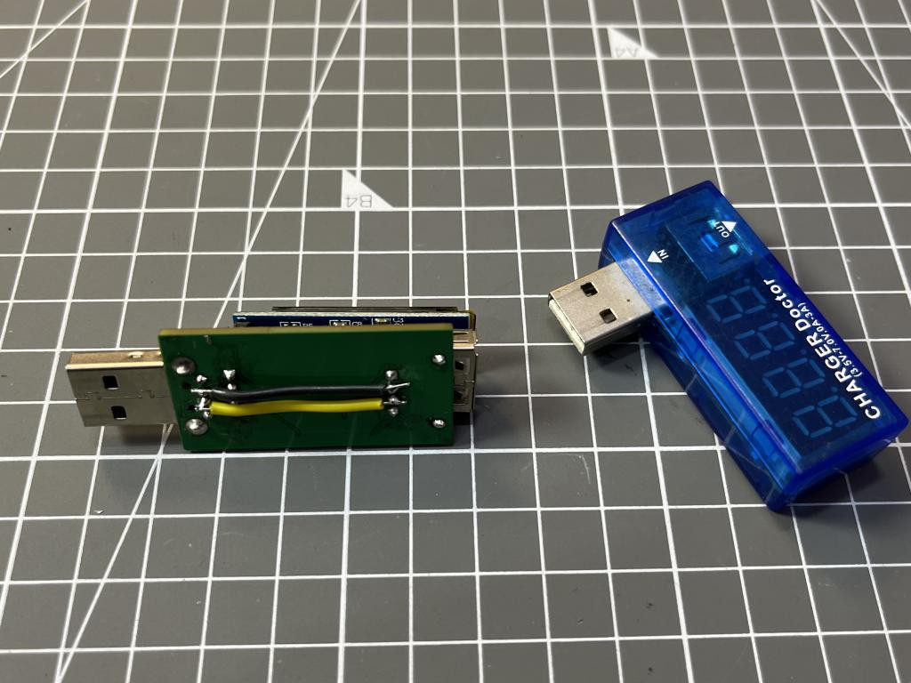
All the connection details are given here in the schematics. Keep one thing in mind, If you want to use this USB charging doctor with fast-charger then datelines of USB need to be connect to each other. Phone gets an interrupt using these data-lines when a fast charger is detected.
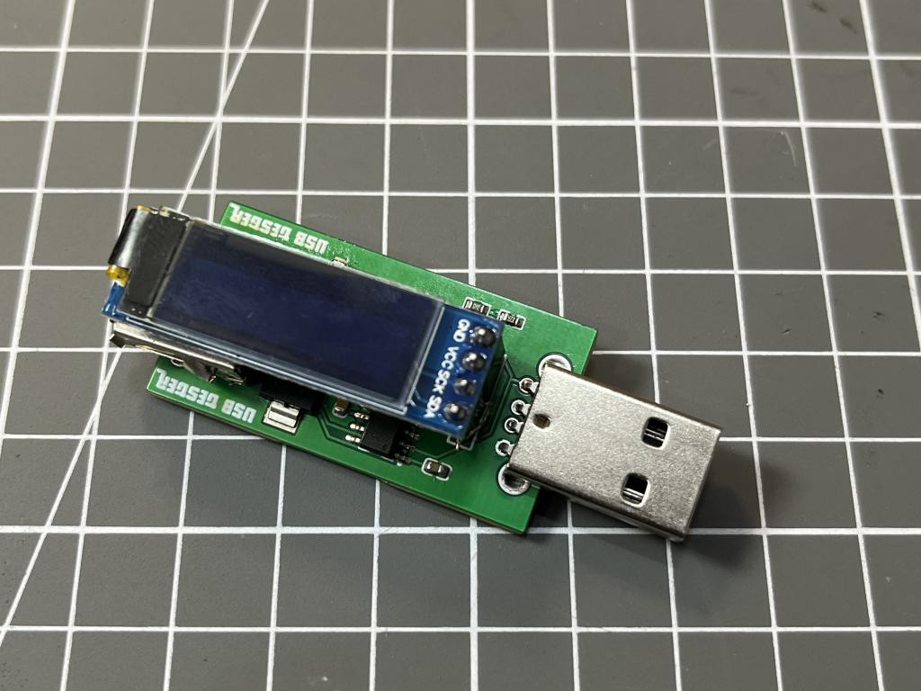
PCB and design:
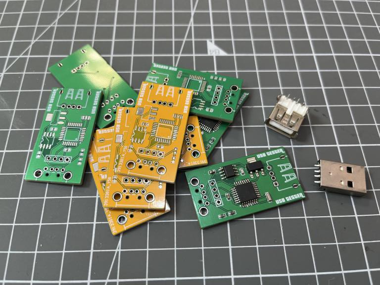
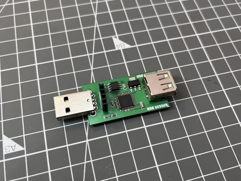
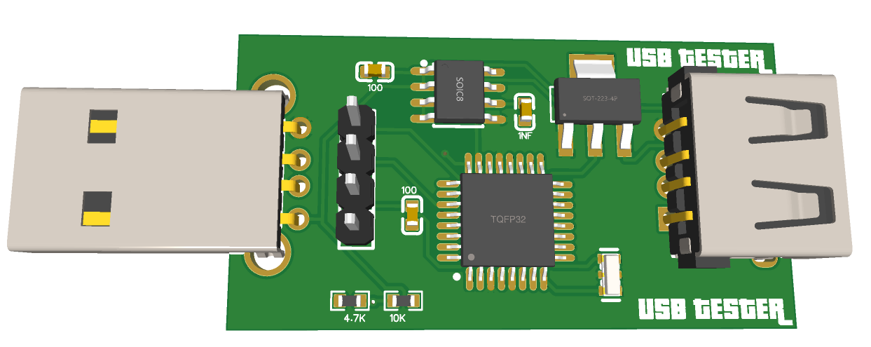
I made a really small PCB having microcontroller on one side and on board pin headers for the small screen. One male and female USB connector, to give power to the system and other one for the power output. I will recommend to use USB 3.0 socket because they are more durable and has very good connection approach.
You can download the Gerber files from here, my PCB is made using FR4 material and HASL finish which costs me around $2 for the 5 piece. You can also use SMT assembly service offered by JLCPCB at a very low cost starting from just $8. Sign-up now to JLCPCB and get free coupons of worth $54 as new user.
Code for the USB DOCTOR:
The code utilises some basic LED driver and current sensor libraries. You can download all the libraries directly from the manage library section under the tool menu.
// Suitable with 12v battery, adaptor wattage, current and voltage monitoring.
// Resistor divider network need more upgradation if voltage is higher that 15.6
// Try 0x3f OLED address if screen did not work.
// Precision of the voltage depends on the tolerance of the resistors.

#include <Wire.h>
#include <Adafruit_GFX.h>
#include <Adafruit_SSD1306.h>

#define OLED_RESET -1
Adafruit_SSD1306 display(128, 32, &Wire, OLED_RESET);

void setup() {
  // put your setup code here, to run once:
  Serial.begin(9600);
  display.begin(SSD1306_SWITCHCAPVCC, 0x3C); // Change the address to your's one
  display.clearDisplay();
}

void loop() {
  // put your main code here, to run repeatedly:
  int adc = analogRead(A0);// current
  int adc2 = analogRead(A1); //voltage
  float voltage = adc * 5 / 1023.0;           // Currrent value... Both ADC values converted into voltages
  float voltage2 =...
Read more »
 puneet1984
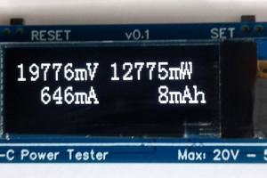
 Mrinnovative
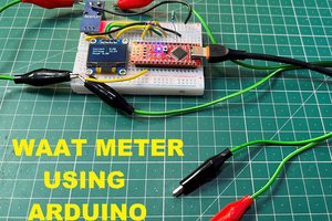
 Sagar 001