 Christopher Xu
Youtube channel with short videos
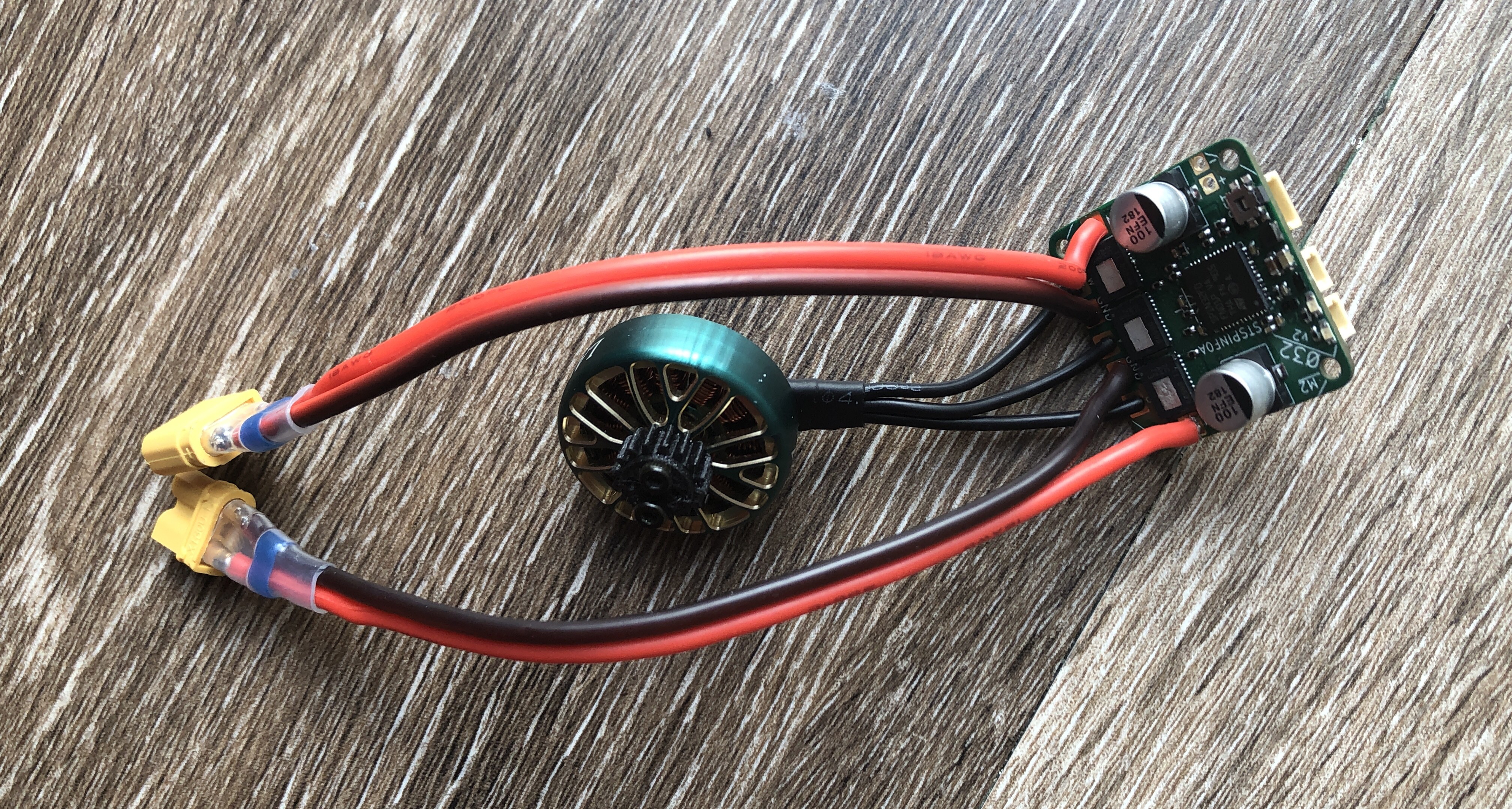
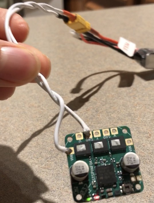
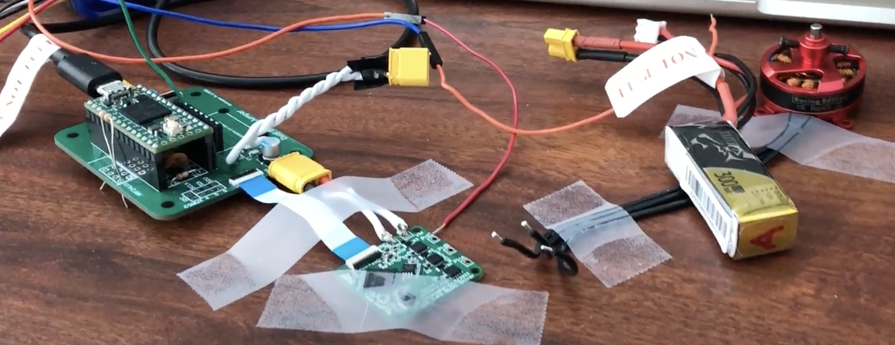
Application project of motor driver
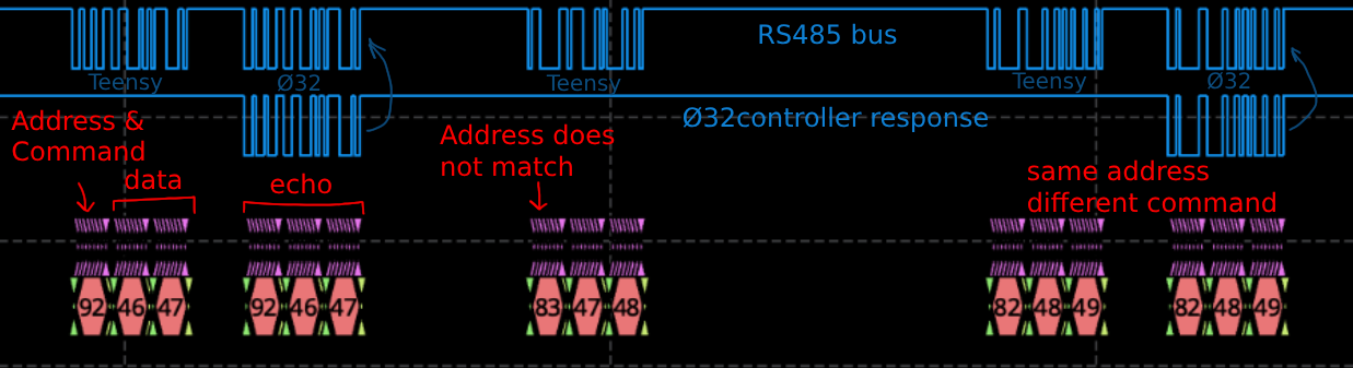
Works with my RS485 controller
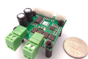
Specs:
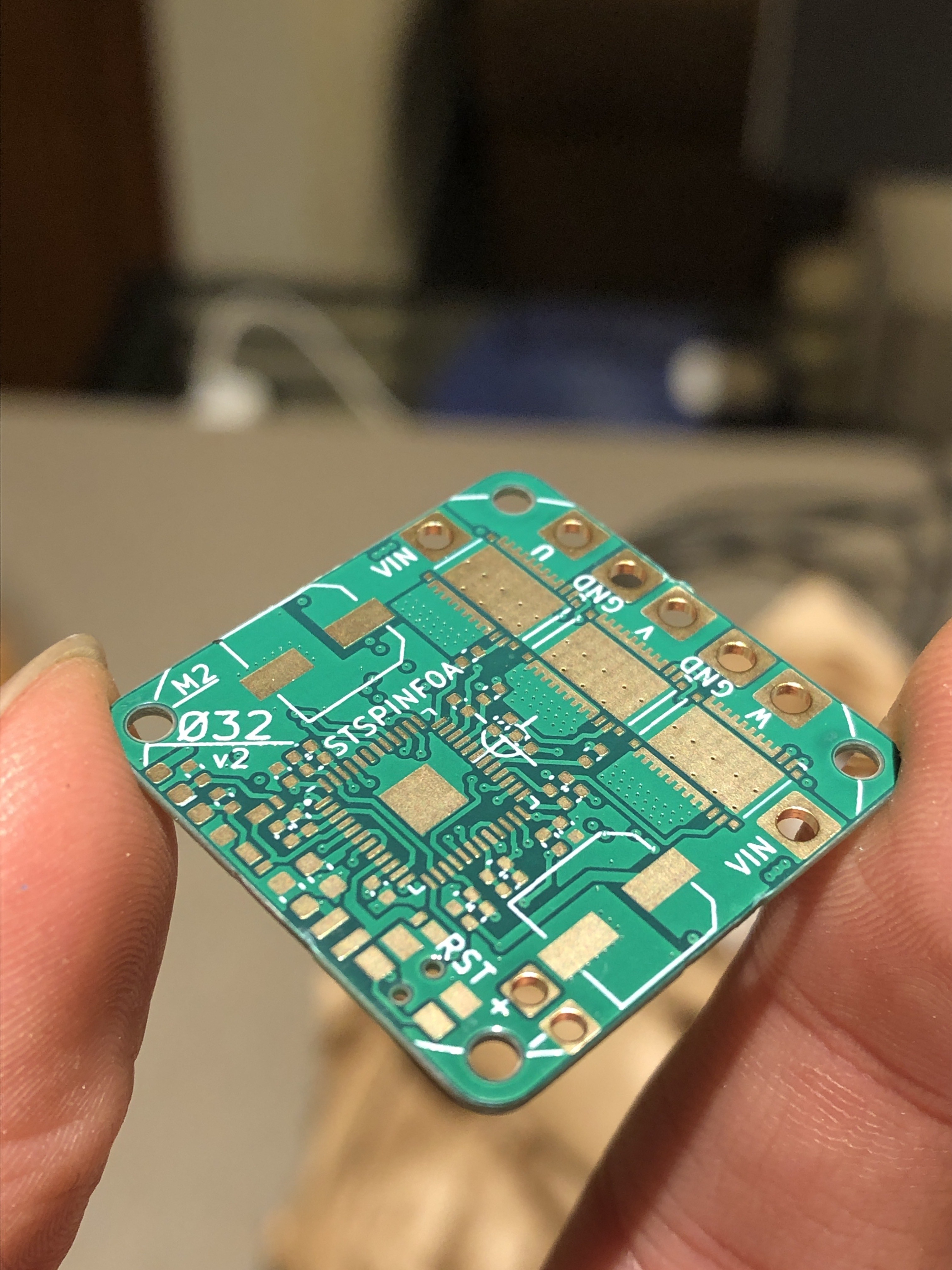
- M2 mounting holes on a 32mm diameter circle
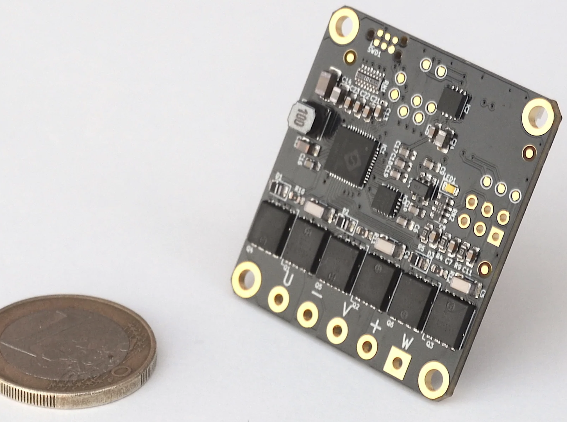
- 27mm x 27mm x 0.8mm, 4-layer, 1oz copper PCB
- 7-15V input, built-in voltage sensing
- Internal temperature sensor
- 12-bit magnetic angle sensor
- 3 shunt current sensing and overcurrent protection
- 2x 2-pin JST-SH connectors for I2C for RS-485 communication, allowing daisy chaining
- 1x 4-pin JST-SH connector for Serial Wire Debug programming and UART output
- External SPI for mounting encoder farther away
- NTC thermistor for monitoring coil temperature
Critical components:
- STSPIN32F0A BLDC gate driver and Cortex-M0 MCU
- MA702 magnetic angle sensor
- CSD88584Q5DC dual MOSFETs (40A continuous)
Tested:
- 12200 rpm with a 1800KV motor
- 12A bus current at full torque stall
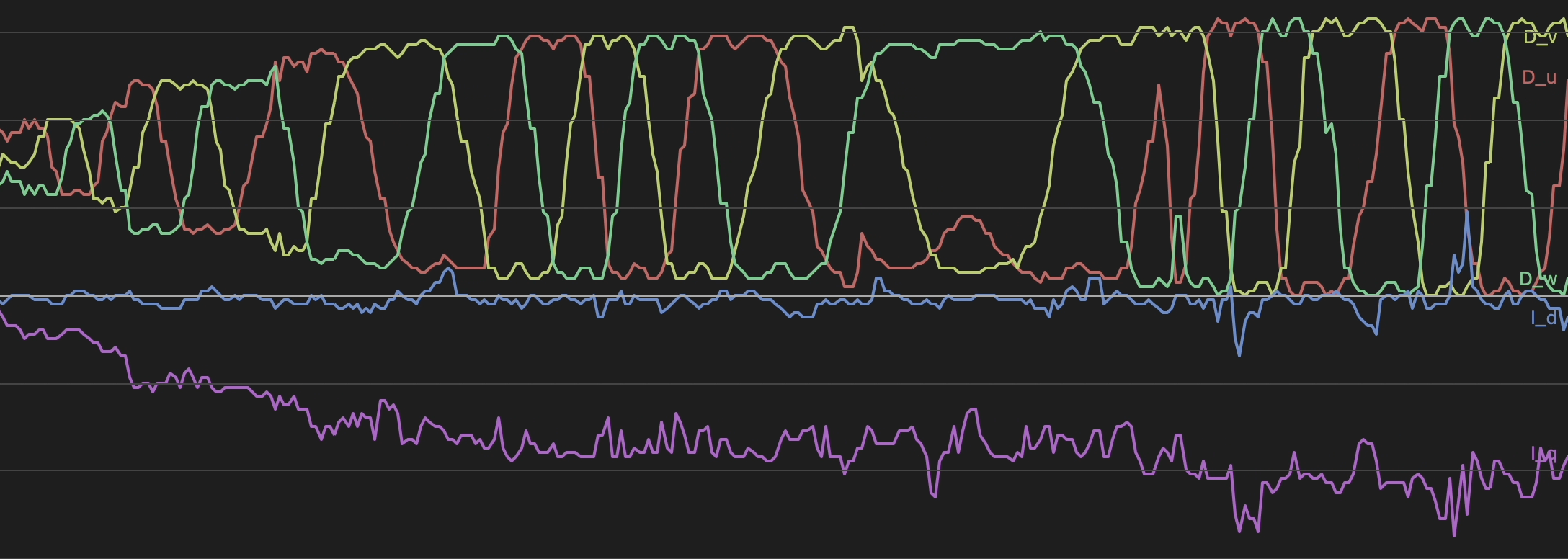
- Position, velocity, voltage, and current control over RS485
- Field oriented control (FOC)
Should be possible:
- 50A continuous, 110A peak phase current
- Temperature-dependent current limiting
Status: Currently working on NTC temperature monitoring and current control loop gains


 ottoragam
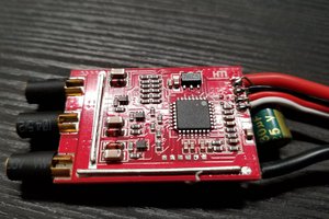
 Anthrobotics
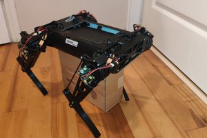
 Peter Wasilewski
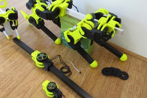
 Paul Gould
Do you wanna make regenerative braking a feature in the future?