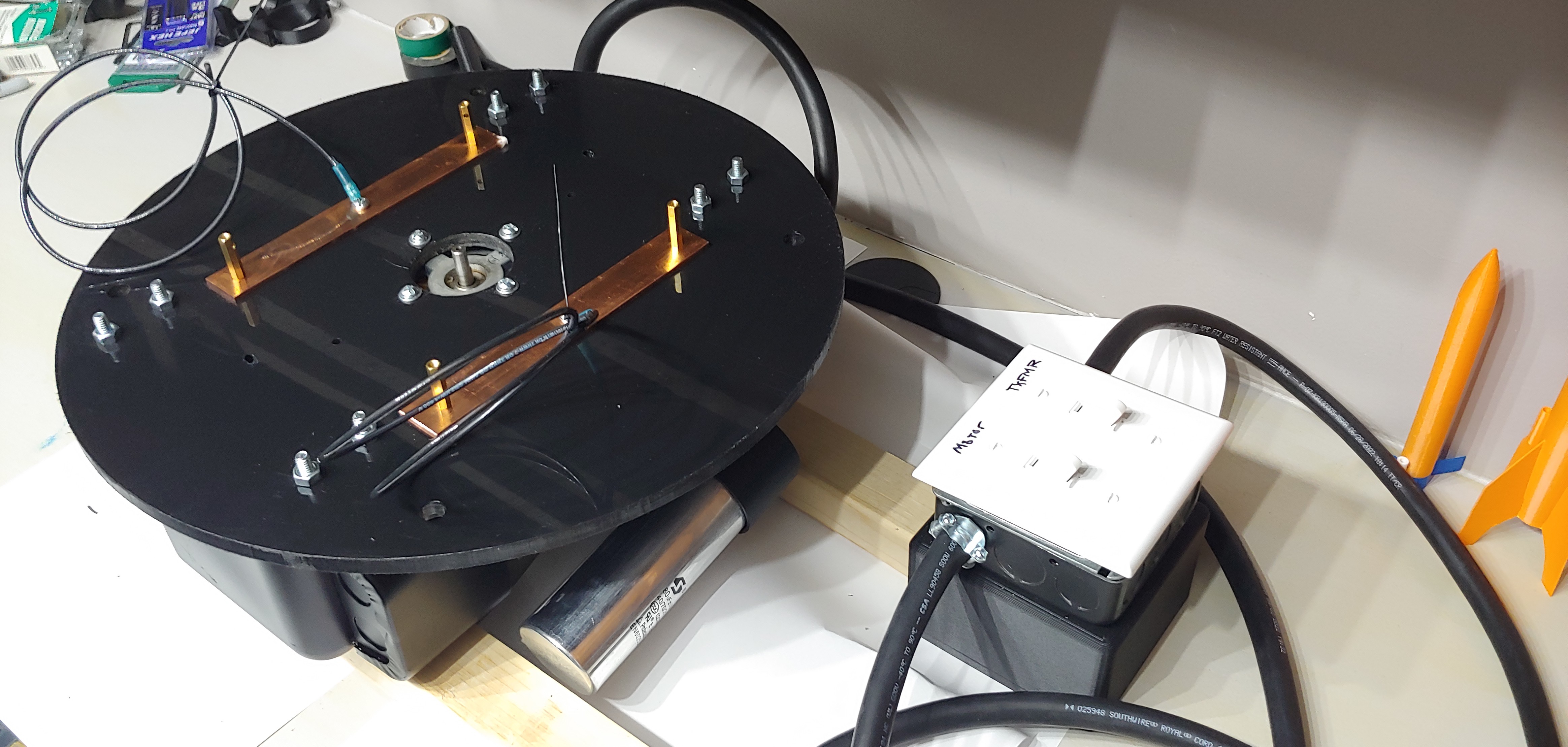
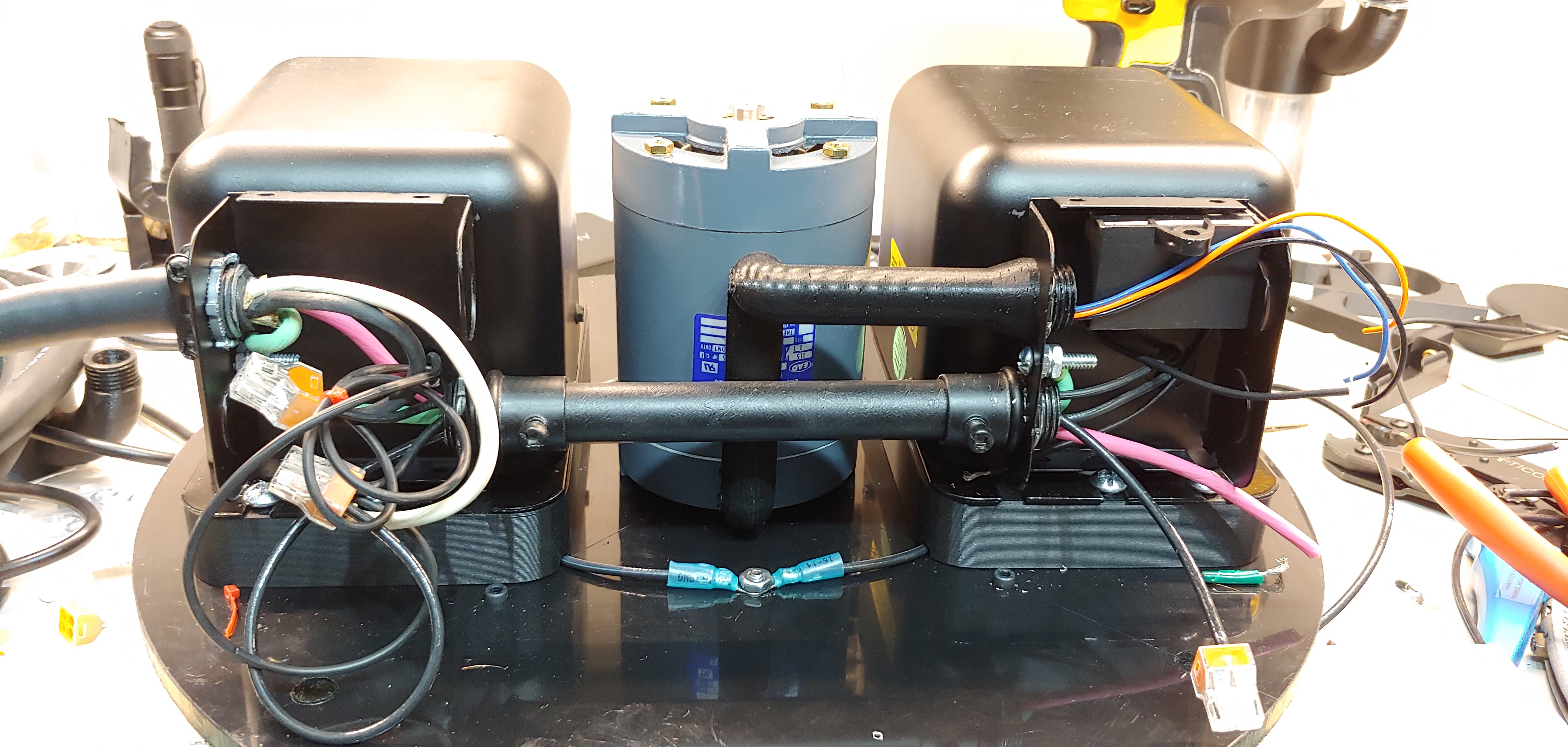
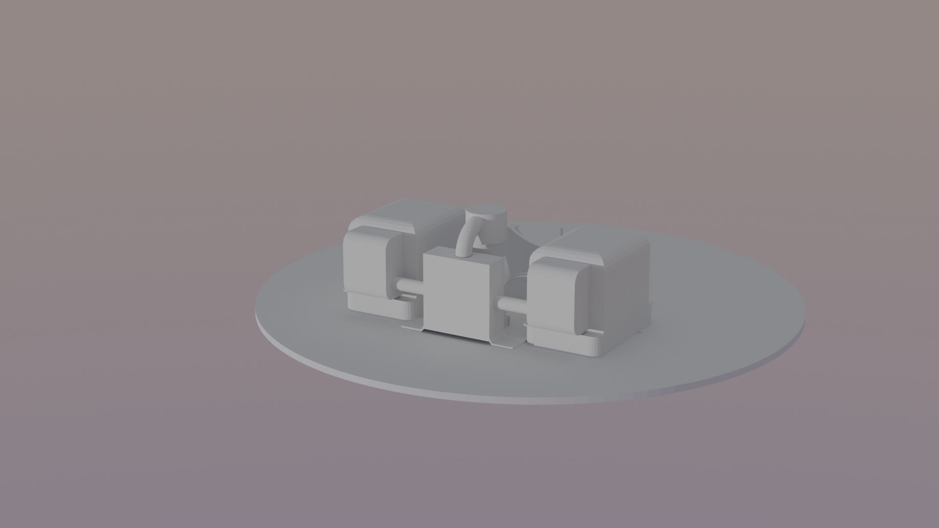
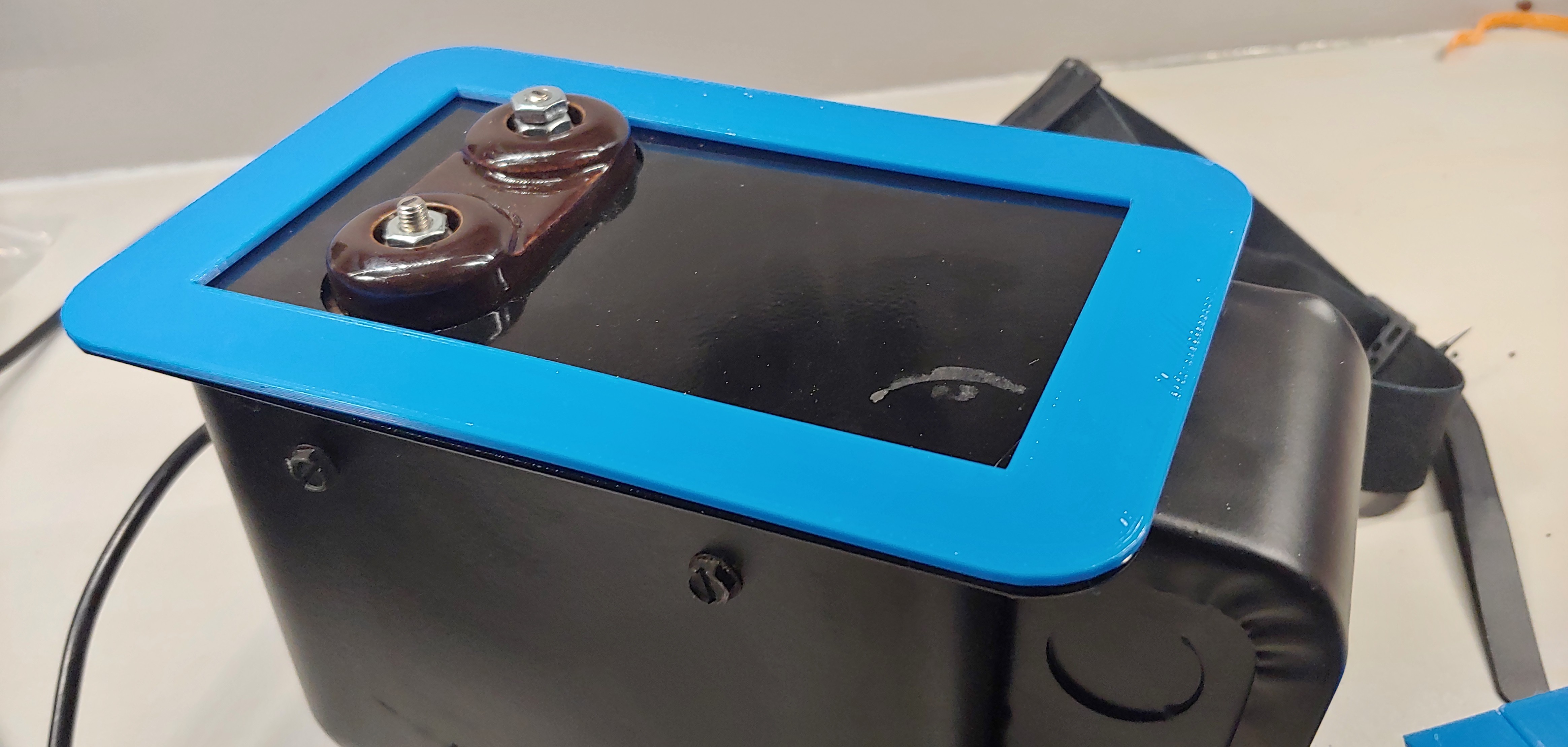
• Switches & Supply

    George Gardner01/25/2023 at 02:47 0 comments

    Tonight I continued down the supply side, adding a 1900 box with switches and an EMI filter. I printed a custom case for the EMI filter that attaches to the 1900 box, then used a grommet to bridge the wires between the two. 

    The two boxes marry together with a couple nuts and bolts, which I conventiently used for the grounding lug. 

    After getting everything wired up, I gave it a quick test to make sure the motor runs and transformers power up without any internal arcing or other abnormal behavior. Everything started right up with no issues. I believe the next step in this process is to figure out the MMC layout and get them soldered together. 

  • Starting the Build

    George Gardner01/24/2023 at 00:40 0 comments

    So, the project has gone under many changes, the largest of which is the layout of parts on the chassis. Turns out when I was modeling the base, I entered the diameter instead of the radius, causing me to believe that I had twice as much room (4x the area). In essence, I had much less space and had to re-think and re-orient all the parts. 

    The new plan is to keep the transformers in a straight line, and rotate the motor upwards, mounting it in the vertical position between the two transformers. The middle part of the chassis is now planned to be used as a result. Previously, I decided I would double up on the bottom layer, but that is no longer an option. 

    The power factor correction capacitor will go on the power input side of the transformers, still with a custom conduit cap leading from one of the knockouts on the transformer input. In addition, I've modeled a custom conduit to lead from the motor, where the wires protrude, back to the boxes as well. 

    The PFC cap will mount to the base with custom printed brackets. There are (2) unused knockouts on the insides of the transformers that I will use to run the power from box to box. This will be standard EMT conduit with couplings. While the (2) boxes may get grounded together, I'll be running an additional grounding wire that is bolted to the chassis of each transformer to ensure they have a good ground connection. 

    I've read the case where the transformers should be connected to RF Ground, and others who say it should be connected to mains ground. After much reading, I've decided to go with grounding the transformers to mains ground and making use of an EMI filter. In a parallel combination, which is what I'm doing with (2) transformers, the cases should definitely be grounded to each other. Before running the parallel wires between each transformer, it's important to check phasing to make sure they're in phase with each other. There's a good video by Chris Boden of the Geek Group on phasing if you want to check that out below. 

    Basically, it entails bringing one of the hot HV leads from one transformer over to the other while they are both in operation. If an arc jumps across, they're out of phase, and these (2) leads should not be connected in the final build. Bear in mind that if you reverse any of the wires on the low voltage (mains) side, this phasing will change. Once I determined phasing, I put green electrical tape on each of the mains wires so I didn't hook them up backwards on the final build. 

    My transformers were identical - same make, model, size, etc,.. and oddly enough, the wires coming out of the primary side (there's a top and bottom wire) were not phased with each other, meaning I had to connect the upper wire on one transformer to the lower wire on the other to ensure the secondary side leads were phased with each other. So don't ever assume the internal wiring is the same - even if you have two identical transformers! 

    I purchased 12 gauge, 4 conductor wire as input to the transformers. The thinking there is (1) neutral, (1) hot for transformers, (1) hot for asynchronous motor, and (1) ground. I wanted independent control of both the transformers and the motor to ensure the motor is fully spun up before activating the high voltage transformers. 

    As seen below (on right transformer), the 4uF start/run cap for the asynchronous motor conveniently fit inside one of the transformer's electrical housings. 

    You can also see on the left side of each case, the grounding wire bolted to each case. Also notice the transformer mounting spacer used, which puts the total depth of the transformer w/ mount about 3 millimeters deeper than the motor. The idea here was to use 3mm felt pads (seen below) so the motor is not sitting directly on the base causing unnecessary noise -- like it won't be loud enough to begin with. 

    In the above image, the top is facing down, so the HPDE seen below the motor and...

    Read more »

  • Preparing & Modeling Parts

    George Gardner01/18/2023 at 00:24 0 comments

    I've begun the teduious process of measuring and modeling all the parts and pieces, and I'm starting to make preliminary parts. 

    In the above render, you can see the two OBITs, connected by two conduits with a 1900 box in the center. Behind the 1900 box (hard to see) is the power factor correction capacitor. I modeled a custom cap with a conduit for it so there won't be any exposed line level voltage wires hanging out. Otherwise, the cap has some pretty exposing terminals on it that I wouldn't be satisfied with leaving it in that condition. 

    I went through the trouble of modeling threads on the 1900 box adapter so I can use a standard EMT nut (14 threads per inch if you're wondering). 

    You can see the transformers are facing down towards the HPDE. I chose to have the high voltage terminals on the Transformer facing down for this build. Again, another safety consideration (not that I'll be anywhere near this thing when it's firing). I printed a few test pieces to make sure my measurements were correct. 

    For the HPDE, I mounted a small strip of masonite to my wood router to made the radius & circle cut. I wish this stuff didn't scratch so easily! 

    I was originally going to have a chassis with (3) layers, but decided on omiiting the middle platform for a single base and single top piece. I'll likely double up the bottom layer (using the middle layer) due to the weight of all the components. I could use the extra support at the base as a result. 

  • Winding the Secondary

    George Gardner01/17/2023 at 01:15 0 comments

    To make life easier, I modeled and printed a winding jig that supported the standard 608 bearings, along with a holder for the drill

    The part that attaches to the drill also contained an actuator that contacts a microswitch for counting revolutions. This was attached to a mechanical counter. 

    After the coil was wound (timelapse below) I used some brush on polyurethane. The counter didn't work as I intended, as I forgot to solder the wires and they became disconnected during the process. I was shooting for approximately 16.8 inches of winding, but ended up adding another inch or so, as I planned to remove some of the lower threads and cut the bottom to height. After the below video, I ended up winding another secondary. The reason being was the poly had just come from the garage and was cold and thick, which made for a very unattractive appearance. On the second coil, I used kapton tape around the base and top so the poly would not distort the clean look of the plexiglass form. In addition, I ended up soldering the wires to the counter and ended up with 1,180 turns. This number will decrease, as I plan to remove the first few windings at the bottom. 

  • Secondary Form & Chassis Material

    George Gardner01/15/2023 at 15:06 0 comments

    I've opted for an acrylic tube secondary and decided on black HPDE for the chassis. The tube I purchased is ~3" Diameter x 24" long , so I'd be looking somewhere around 18" of winding for a 6:1 coil length to diamer aspect ratio. This ratio was obtained by the guide at http://deepfriedneon.com/tesla_guide.html. I've read other sites which claim the maximum should be 5:1 and others that state you should be in the  area of 4:1-6:1.

    Plugging in known values into TeslaMap, I can see I'd be shooting for a capacitance of around 31.8 nanofarad using a synchronous rotary spark gap. Much reading has yet to be done on my end for the spark gap. 

  • Preliminary Thoughts and Transformer Selection

    George Gardner01/14/2023 at 14:32 0 comments

    So here we begin the long journey of an attempt at a tesla coil. My aim is to create a medium sized tesla coil, and after having watched hours of videos and read through many websites and a book, feel as though this is a journey that will not be fruitless. 

    This project will be fully designed and layed out prior to constructing a single component. While during the construction of a tesla coil, there are many components that are highly variable, such as coil diameter, number of turns, capacitance, etc,.. , there are some components which are a bit more rigid in terms of variability. Such is the transformer, which is largely determined by availability and cost. 

    While funding for this project is finite, I have chosen to use an oil burning transformer in lieu of the commonplace neon sign transformer found in many TC projects. They are typically offered in 10,000 volt, 23ma variants. According to http://deepfriedneon.com/tesla_guide.html, the spark length is proportional to the power output of the transformer. Consequently, we can either change the voltage or the current supplied by the transformer to alter the power output. 

    As a result, my plan is to use (2) identical OBITS (oil burning ignition transformers) wired in parallel for twice the output current. We cannot, in this instance, series wire the transformers and expect they will not catastrophically fail, according to many people more experienced than myself.

    I have purchased (2) new OBITs, shown above, for this venture. The cost, combined, was less than that of a single NST, albeit slightly lower current output as a result.