 Arya
AryaNothing's better than reverse-engineering, right?  Well, maybe I can actually learn something from the existing parts, especially provided there are so many DIP-8 ICs shipped with Fritzing. I'm creating everything from scratch, but this saves my frustration for me and time for readers.
Fritzing is huge - 182MB archived, 360MB unpacked. I can go make hot chocolate while the archive is unpacking.
Fritzing has a folder named "fritzing-parts" inside, wonderful! What's inside?
bins/ #Seems like binary files go here?
      #two .fzb's inside - what are those?
----more/ #Icons in PNG and .fzb's.
          #Something about libraries?
contrib/ #Empty in stock install.
         #Probably for whatever libs you download.
core/ # a lot of .fzp's - "Fritzing parts"? Seems so!
Didn't even need to scroll far to see a part named ATtiny85.fzp. Look inside:
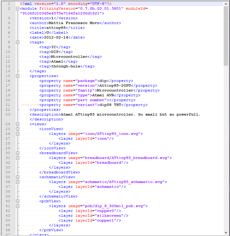
XML. Not a bad choice here, though JSON would take less space - but it works pretty well and is very readable. However, the SVGs are XML and using XML and JSON in one app heavily is likely a clusterfuck. The space hog is the SVGs anyway (they take 125MB in stock install, and another 131MB is Git history).

So, parts make heavy use of SVG layers and IDs. Wonder how usable it will be in Inkscape...
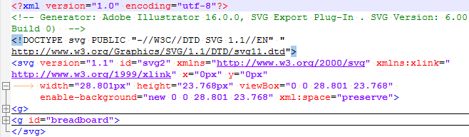
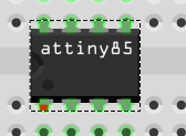
The paths shown in svg seem to start from fritzing-parts/svg/core. Let's see those and determine how hard it's to make a part from scratch and where it could be optimized. First, the breadboard view:
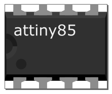
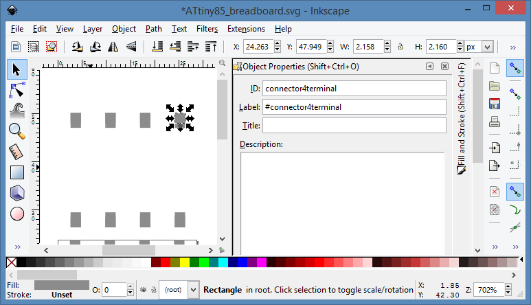
A little bit of pulling layers apart and ungrouping:
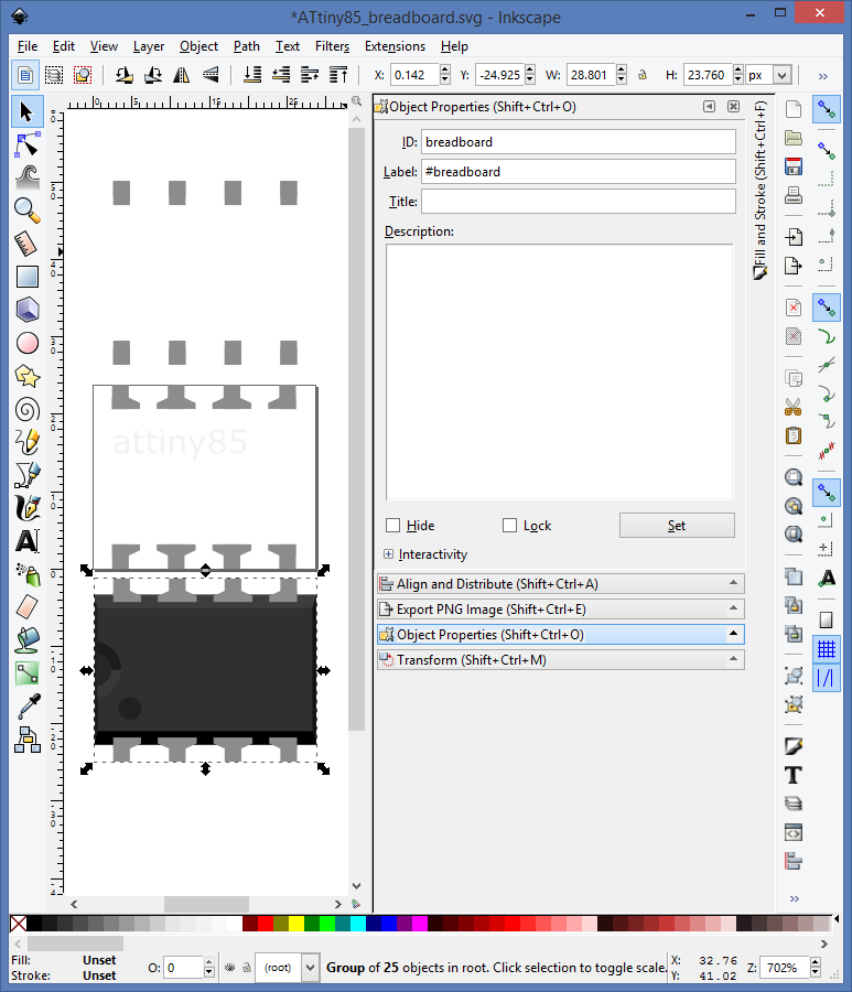
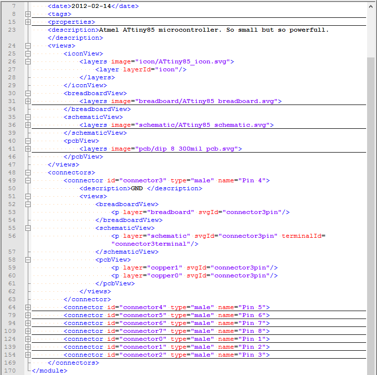
The thing selected is the #breadboard SVG object, as you can see in the upper right. Wonder if that's "layerId" from the breadboardView -> layers -> layer (in SVG excerpt just above), I'm not in the mood for testing (Fritzing loads slowly) and will just assume it is. What else is mentioned out of SVG elements? Connectors, that is - pins!
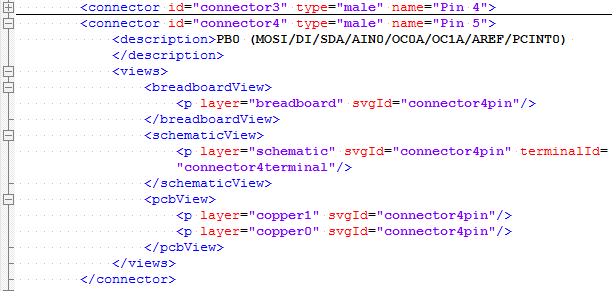

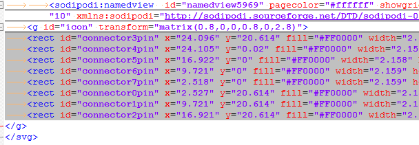
Funny how the connector4terminal is there, but only mentioned in schematic view. Now, the SVG source:
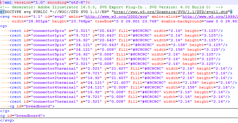
I get it, this is autogenerated, but duplicate IDs aren't really the best idea ever. If you look through the file, not only "breadboard" ID is duplicated, but the "connectorXpin" are too. If it's interpreted how I figure it should be interpreted... Let's see.
IDs in .fzp:
- breadboard
- connectorXpin
Additional IDs in SVG:
- connectorXterminal
- Duplicate "breadboard"
- icon
That's it. Let's fix the .SVG by removing all the useless things - it's a little hard because I don't know what's useful and what's not. Thankfully, workflow is simple - editing the SVG in Notepad++ and reloading the Inkscape view:
Will not describe the entire process - too much talking for 15 minutes of work
Editing SVGs manually, what could go wrong?
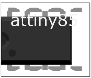
After this, I started making more granular changes and eventually got there.
End result:
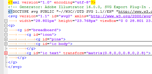
Redundant tags are there just for readability. Though, come to think of it, that outer <g> is not needed - removed.
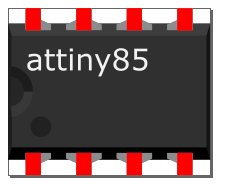
It looks alright in Inkscape, let's put an ATtiny85 on a breadboard in Fritzing... Crap, it looks the same. How do I know it's changed? Let's color pin 1 red:
Seems like that to test the changes in SVG, it's sufficient to delete the component and place it again. Nice! Footprint works, and there are no duplicate IDs/graphics, and half as much SVG lines.
So, bare minimum should be:
<g id="breadboard">
	<g id="icon">
		<g id="pins">
			<rect id="connector0pin" x="2.521" y="20.643" fill="#FF0000" width="2.16" height="3.125"/>
			...
			<rect id="connector7pin" x="2.521" y="0.008" fill="#8C8C8C" width="2.16" height="3.125"/>
		</g>
		<g id="ic_body">
			<!-- Polygons for graphical IC representation -->
		</g>
	</g>
	<g id="ic_text">
		<!-- IC name layer -->
	</g>
</g>
Oh, and all the header cruft.
Next step? Drawing the simple outline with all the pins in Inkscape!
Thoughts:
- It could be possible to reuse breadboard footprints by having a PCB body layer in one file and IC name layer in another file then combining them somehow. I feel like there's a way to do this already, but don't have a clue yet - maybe I will look into that.
Discussions
Become a Hackaday.io Member
Create an account to leave a comment. Already have an account? Log In.
You don't have to edit that XML file by hand. And you don't have to have everything in a single SVG file.
If you right-click on a part in the palette in Fritzing, and select "edit part", it will make a copy of whatever you selected, and let you replace all of the images, define pins, select which SVG elements correspond to which pins in each view, etc. It's really super-easy.
Are you sure? yes | no
I know, I just was geting familiar with what Fritzing needs from SVG files and playing with things. The "Edit part" is the "Super simple tutorial" I made, I discovered it later =)
Unless, of course, you're talking about functionality I didn't notice, which I'll probably check. Do you mean Fritzing can create the .fzp file for you? If so, how do I do it? Never saw an option to export the part I made the super simple way.
Are you sure? yes | no
The "super simple tutorial" thing is yet another Fritzing feature -- that's parametrized parts for stuff like pin headers and chips. But what I meant is the "edit part (new parts editor)" option, which lets you change basically everything.
Are you sure? yes | no
Yeah, I had to modify my tutorial in some places once I found it =) thanks!
Are you sure? yes | no