 IoT-devices, LLC
Functionality
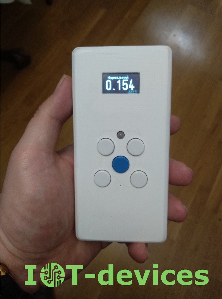
The keypad module connects to the main controller via a 4-wire I2C bus interface and provides the following functions:
- Data entry with a five-button keyboard (left, right, down, up, OK);
- Data output to RGB LED;
- Output of sound sequences to the active indicator of the buzzer type;
I2C bus input and output through ports. Input for connection to MCU and output - for connection of any external devices that support the I2C specification.
Thanks to the use of the I2C bus and the MCP23017 port expander, GPIO savings of the main controller and the ability to input and output information in a user-friendly way are achieved. The rest of 7 GPIOs are connected to separate pin connectors for additional I / O signals connection according to the user's design. Int A & Int B output signals are available - can be used for interrupt processing when the state of the module inputs changes.
Application
I2CUI4_V1 keypad will be convenient to use as a control panel and status display on user devices
- electronic clocks,
- radiation level dosimeters,
- smart outlets,
- thermostats,
- multimedia and audio devices,
- weather stations and others.
Usecase example
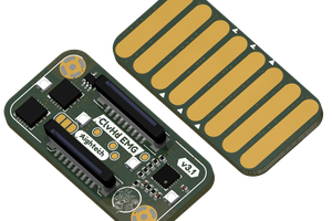
The image shows the application of another of our I2CUI3_V1 modules in a DIY GGreg20_V3-based Geiger counter. The I2CUI4_V1 module is an updated and more versatile version that allows you to build convenient and reliable DIY and IoT solutions for most platforms.
Compatibility
Compatible with controllers and platforms:
- Arduino,
- ESP12.OLED_V1,
- NodeMCU board (based on ESP8266-12),
- modules on the ESP8266EX chip,
- ESP32,
- or others powered by 1.8 - 5.5 V.
Integration into Home Assistant (with ESPHome plugin), Blynk, OpenHab, Node-RED is possible.
Minor and major versions of the module
Unlike the minor version I2CUI3_V1, the I2CUI4_V1 user interface module uses a widely supported 16-bit MCP23017 port expander. This makes it possible to use this module in IoT devices for easy integration in Home Assistant, Arduino and many others.
Chips of user interface modules:
- I2CUI3_V1 - 8-bit, I2C, PCA9538, 2^3 GPIOs;
- I2CUI4_V1 - 16-bit, I2C, MCP23017, 2^4 GPIOs.
The major version of I2CUI4_V1 has the following features:
- single digital interface - 2 x I2C (input / output) ports;
- 5 “joystick” buttons; sound indicator; RGB LED indicator;
- selection of one of 8 module addresses on the I2C bus via solred-pads;
- 7 free GPIOs are connected to separate pin connectors.
Driver-level support
Support for the MCP23017 chip at the driver level is stated in particular by the following platforms:
Assignment of module ports
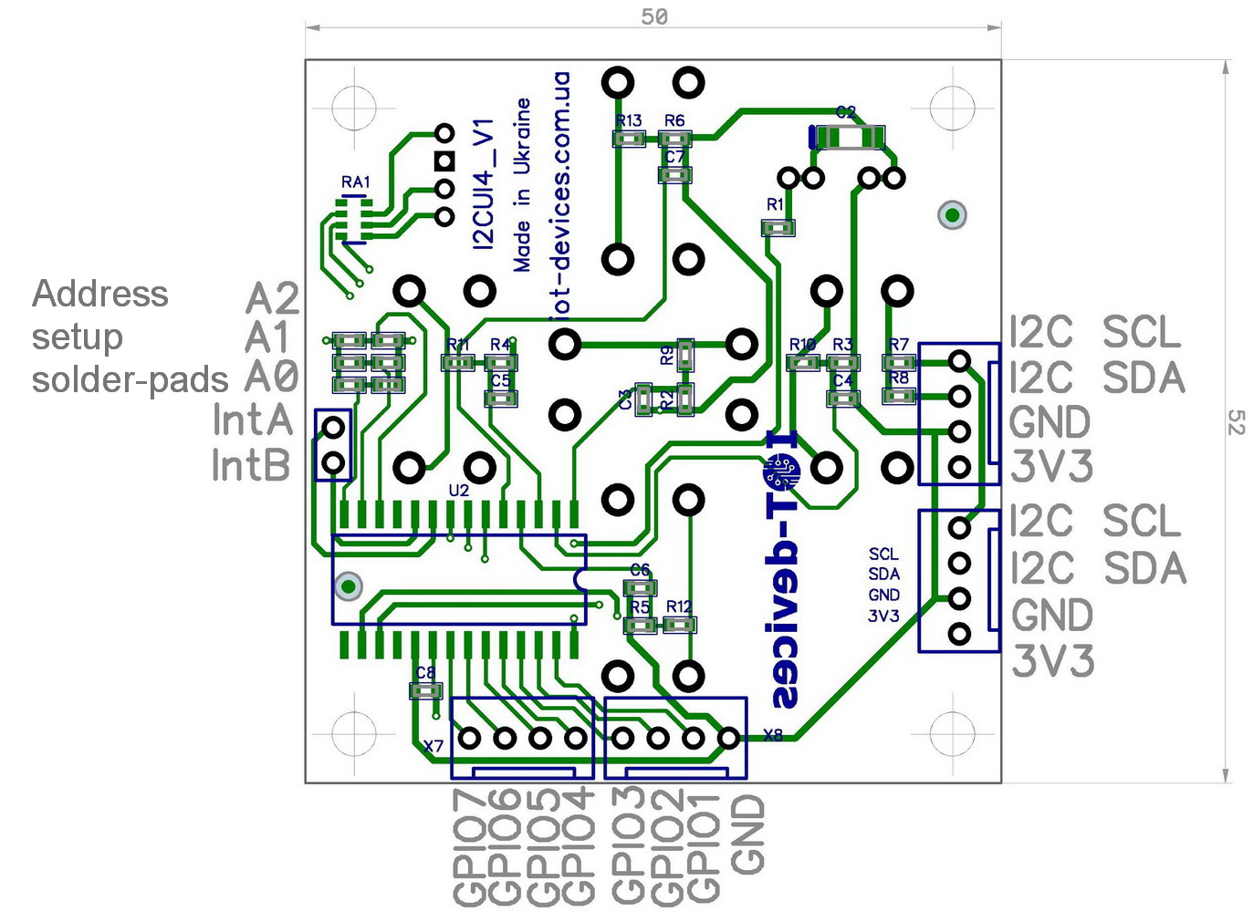
The following ports are provided on the I2CUI4_V1 module board:
| Port Name | Assignment | Logic |
|---|---|---|
| GPIO 0 (GPB0) | Buzzer on board | 3V3 or 5V active high |
| GPIO 1 (GPB1) | Free, for user extensions | 3V3 or 5V active low |
| GPIO 2 (GPB2) | Free, for user extensions | 3V3 or 5V active low |
| GPIO 3 (GPB3) | Free, for user extensions | 3V3 or 5V active low |
| GPIO 4 (GPB4) | Free, for user extensions | 3V3 or 5V active low |
| GPIO 5 (GPB5) | Free, for user extensions | 3V3 or 5V active low |
| GPIO 6 (GPB6) | Free, for user extensions | 3V3 or 5V active low |
| GPIO 7 (GPB7) | Free, for user extensions | 3V3 or 5V active low |
| GPIO 8 (GPA0) | LED - Blue on board | 3V3 or 5V active high |
| GPIO 9 (GPA1) | LED - Green on board | 3V3 or 5V active high |
| GPIO 10 (GPA2) | LED - Red on board | 3V3 or 5V active high |
| GPIO 11 (GPA3) | Key Up on board | 3V3 or 5V active high |
| GPIO 12 (GPA4) | Key Down on board | 3V3 or 5V active high |
| GPIO 13 (GPA5) | Key Left on board | 3V3 or 5V active high |
| GPIO 14 (GPA6) | Key Right on board | 3V3 or 5V active... |
 Aightech
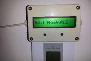
 Ruslan
The designation "I2CUI4_V1" likely refers to a specific version of a user interface (UI) keypad utilizing the I2C communication protocol, commonly used in electronic devices. The "4" might indicate the number of keys on the keypad, and "V1" likely signifies the version number. This UI keypad is designed for easy integration into electronic systems, offering a simple and efficient interface for users. With 5 keys, it provides basic input functionality for navigating menus, selecting options, or controlling various functions within a device. The use of the I2C protocol ensures reliable and efficient communication between the keypad and the device it's interfacing with. Overall, the I2CUI4_V1 keypad serves as a convenient input solution for electronic devices requiring a user-friendly interface.