ElectronicABC
GERBER PCB :
https://mega.nz/file/uNQj1LwI#mqYhVisXP4zY4DqZX5PRBSEoG2oQuzNoXeyr9paDnjs
SCHEMATIC DIAGRAM
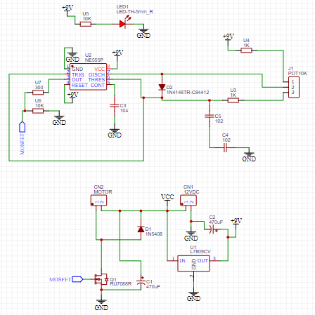
Here we can see the schematic diagram with all the values of the electronic components to be used. the schematic diagram was made in the EASYeda design program.
The Electric Shutter
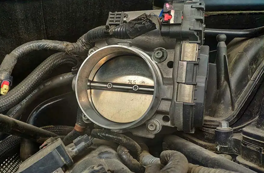
Cars today are equipped with an electronically controlled throttle (ETC). If I try to increase or decrease the idle speed, there is no way to manually adjust it with a screwdriver. My client will also not be able to open the throttle by stepping on the accelerator pedal. The engine control module (PCM) is the only one that directly controls the opening angle of the throttle. If the minimum is accelerated or off or is going down and up, then we are facing bad decisions from the PCM.
Let's analyze its many advantages over the conventional butterfly control. Approximately more than fifty percent of the vehicles produced are equipped with the ETC. Since the PCM has absolute control of the throttle opening, it must first know the combustion needs according to the information from the various sensors that define both the load on the engine and what the driver of the vehicle requests.
During cold engine starts, when emissions are high, the PCM increases engine rpm and will quickly reach its normal operating temperature. Also the catalyst will heat up as soon as possible and start its work. Whether during near smooth driving on the highway or rough driving in city traffic (accelerations and decelerations), the PCM controls the ETC by opening the throttle slightly more than the driver would have done if he had direct throttle control. throttle via the throttle cable or linkage. This "extra" throttle opening reduces engine "pumping" losses that occur as the pistons seek to overcome the vacuum built up in the closed throttle condition. On the other hand, since the butterfly is not directly connected to the accelerator pedal, the PCM better protects the gearbox (manual or automatic) against sudden and irrational driving decisions by the driver. Before the ETC era, the PCM acted directly as a rev limiter, reducing the pulse width for the fuel injectors. Now, with ETC, the PCM controls both air and fuel flow. If the transmission is in park or neutral and someone steps on the accelerator pedal trying to rev the engine, the PCM will limit the throttle opening and thus prevent over revving the engine. The same strategy applies while driving on the highway. No matter how hard you step on the accelerator pedal, the PCM will decide the exact throttle opening angle. And if the driver insists on exceeding the set rev limit, the PCM will reduce the throttle. Also, the ETC coordinates with the stability and traction control systems. Without ETC, the traction control could only use the ABS (anti-lock brakes) and was limited to braking the wheel that had lost traction. This is a waste of energy plus the risk of component damage depending on how panicked the driver is pressing the brake pedal. Now, the PCM combines the ETC with the ABS, reduces the throttle opening and decreases the rotation of the wheel that has lost traction, finally restores the stability of the vehicle.
FUNCTIONING
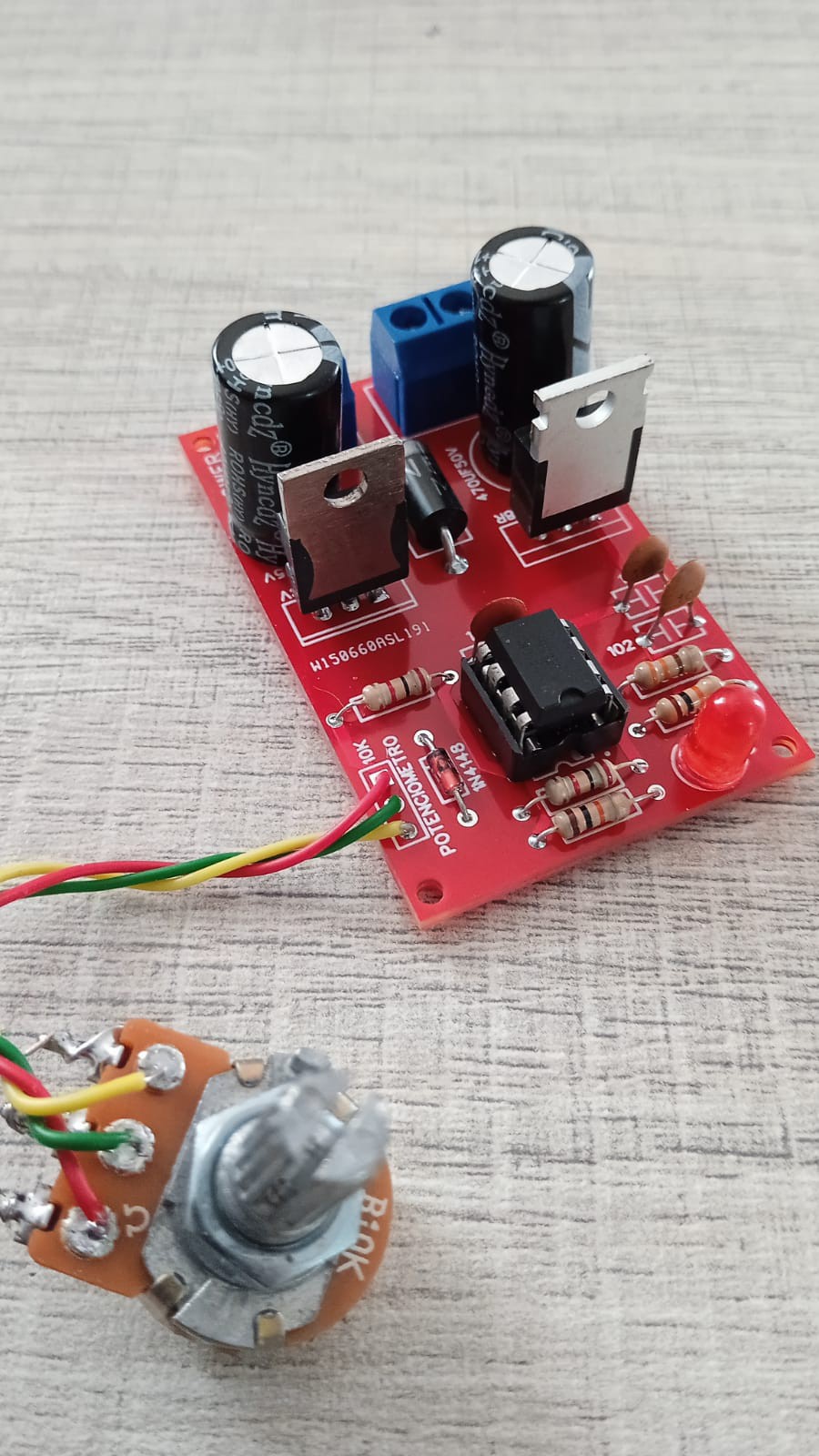
For a component for automotive use, as we have seen in the description of the shutter, its operation and description, now let's analyze a bit, this shutter will be activated by a PWM signal, that is, we have to vary the PWM to be able to open or close the throttle and with these tests we It will give a result of how the shutter is located. It should be noted that the tests are given with the shutter outside the vehicle. then we create a PWM system with the integrated NE555 and we use it in PWM configuration and at the output we use a fast switching MOSFET that is the RU7088R AND WITH A CURRENT PROTECTION DIODE 1N5408.
By varying the potentiometer we will vary the opening and closing of the shutter using PWM.
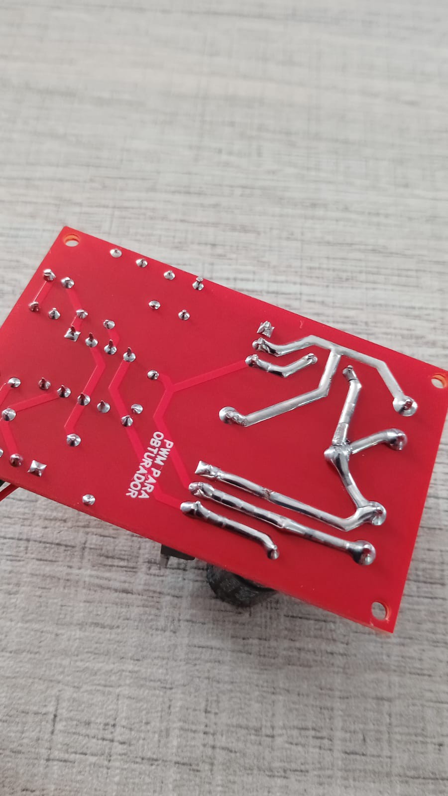
To pass a greater amount of voltage to the output for the shutter, we need the tracks to be uncovered and solder them with more tin so that it can improve conduction and not heat the PCB, therefore in the design of the pcb we have to take into account which tracks will be exposed .
ELECTRONIC COMPONENTS
. 1 NE555
. REGULADOR VOLTAJE LM7809
. MOSFET RU7088R
. DIODO 1N5408
. 2 CAP ELECTROLITICO 1000uF 35v
. 2 CAP CERAMICOS 102
. 1 CAP CERAMICO 104
. 1 DIODO 1N4148
. 2 RESISTOR 10K 1/4W
. 2 RESISTOR 1K 1/4W
. 1 RESISTOR 330 ohm 1/4W
. 1 POTENCIOMETRO 10K
. 1 DIODO LED 5MM
. 2 BLOCK TERMINAL BLUE 2 PINES
. 1 PCB
TECHNICAL CHARACTERISTICS
- VIN VOLTAGE 12VDC
- INTERNAL VOLTAGE OF THE PCB 9VDC
- CONTROLLABLE CURRENT AT THE 2A OUTPUT
- OPENING AND CLOSING WITH THE SAME POTENTIOMETER
- EFFICIENT AND RELIABLE
EASYEDA
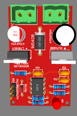
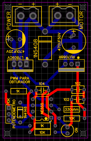
Once the project is finished with all the respective tests, we carry out the PCB design and we will obtain the routed tracks and the 3D image of how our finished PCB would look.
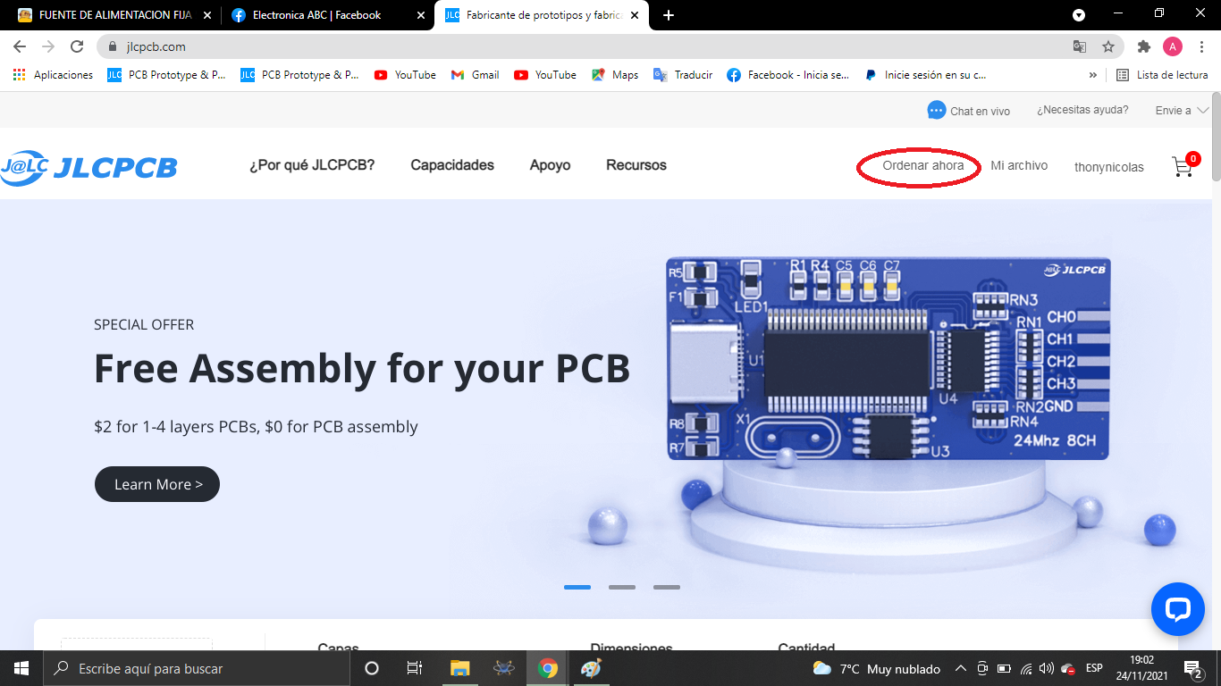
JLCPCB
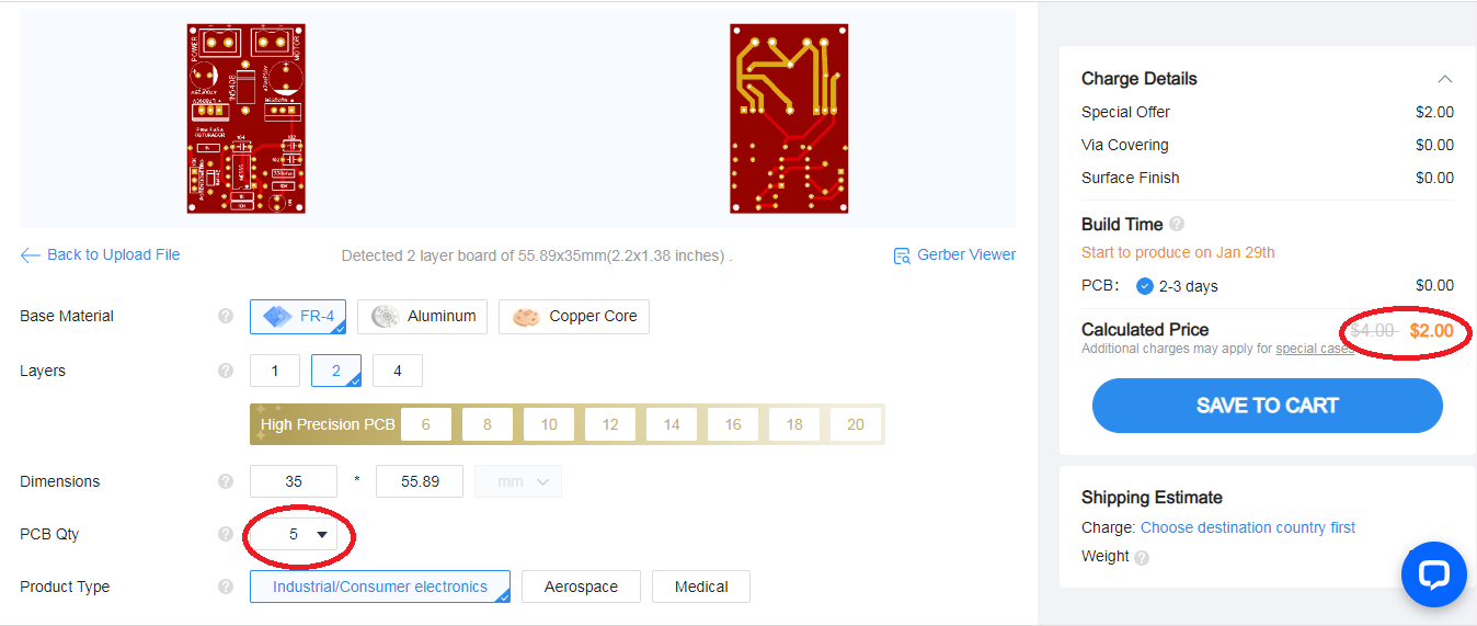
Once the pcb is designed, we will send our friends from JLCPCB to manufacture our PCB.
5pcbs only $2
JLCPCB number 1 PCB manufacturing company worldwide professional pcbs and excellent finish.
GERBER PCB:
https://mega.nz/file/uNQj1LwI#mqYhVisXP4zY4DqZX5PRBSEoG2oQuzNoXeyr9paDnjs
you can get your pcbs in different sizes and colors.