You can find all the data on my github.
0%
0%
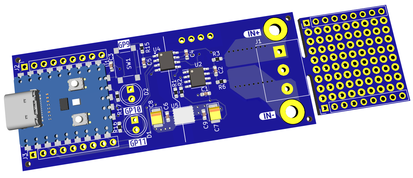
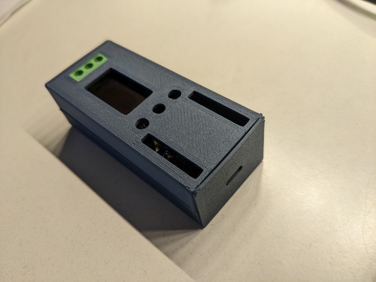
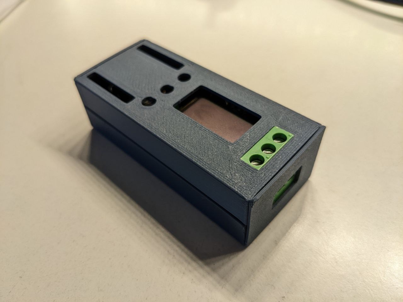
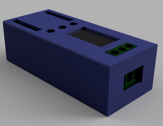
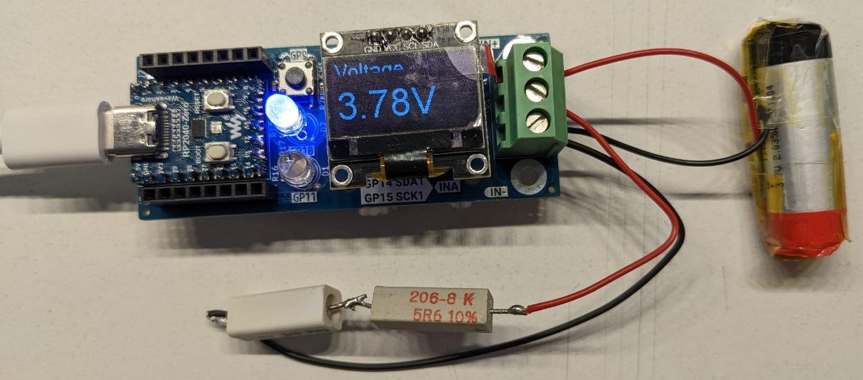
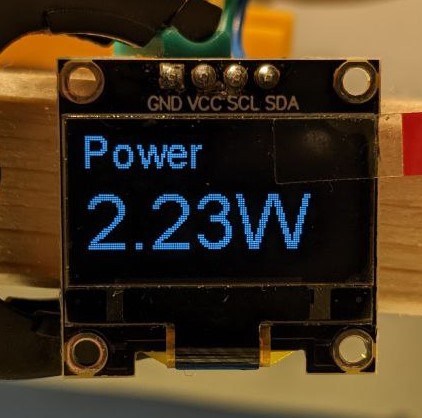
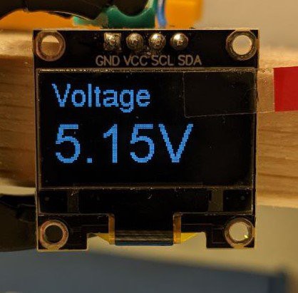
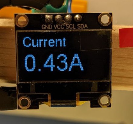
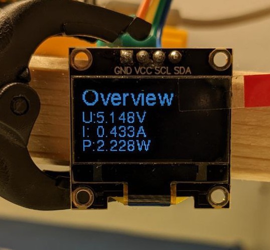
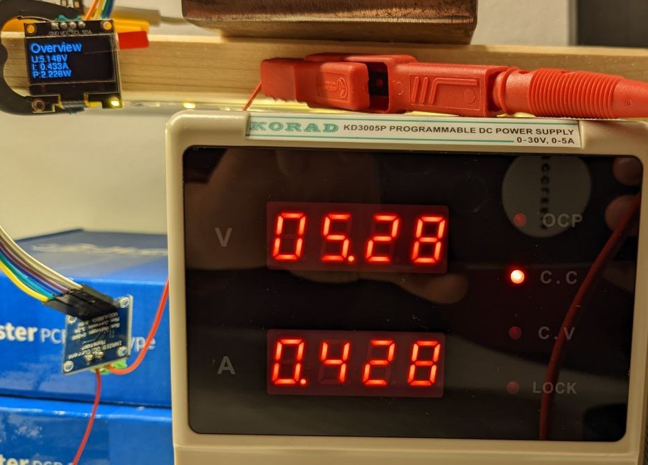
Pi Pico Power Meter
For my electronic developments I need more than one multimeter to get the power. Here it is!
Become a Hackaday.io member
Already have an account? Log in.
Just one more thing
To make the experience fit your profile, pick a username and tell us what interests you.
Pick an awesome username
hackaday.io/
Your profile's URL: hackaday.io/username. Max 25 alphanumeric characters.
Pick a few interests
Projects that share your interests
People that share your interests
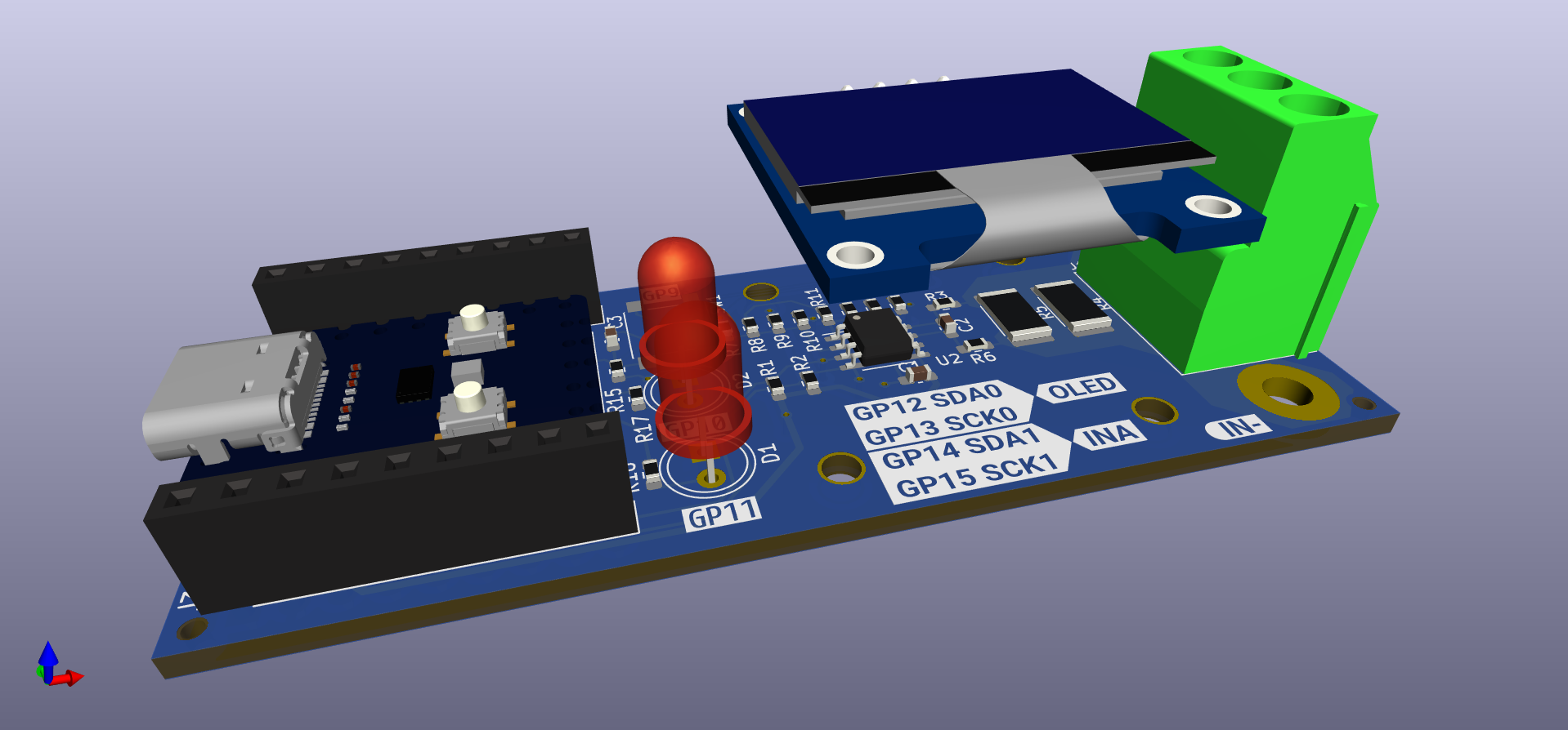
 I disabled the THT components to see below the OLED display.
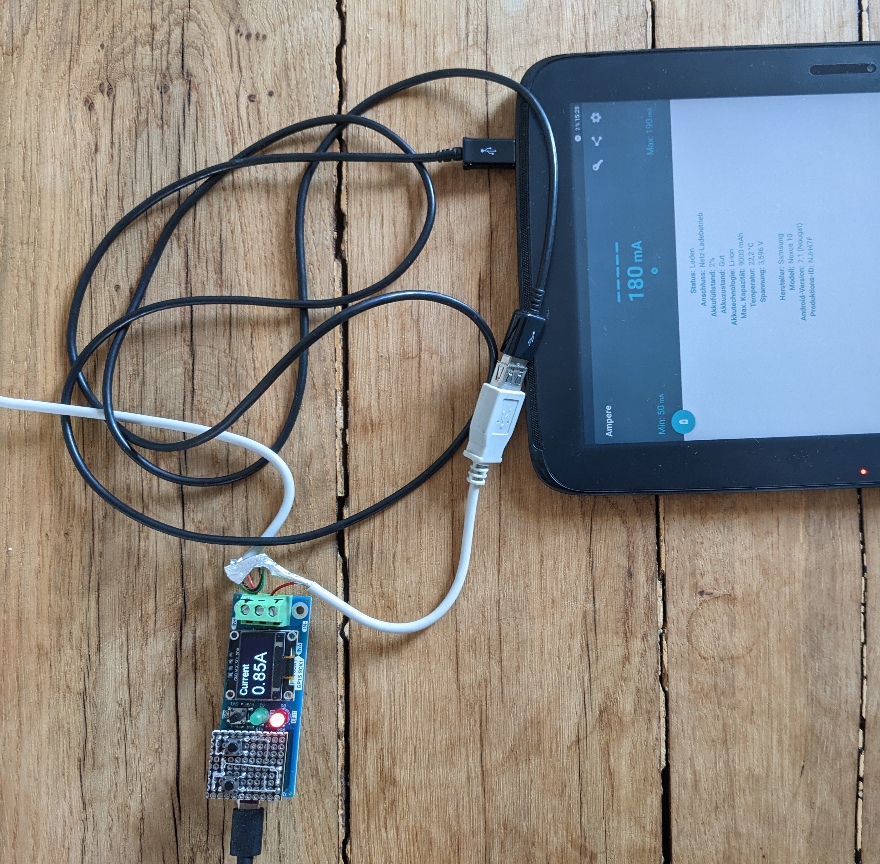
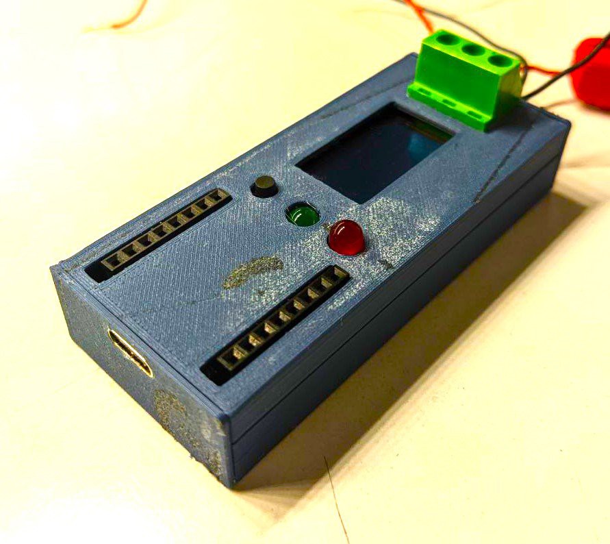 It came out a bit ugly due to a dirty printer bed...
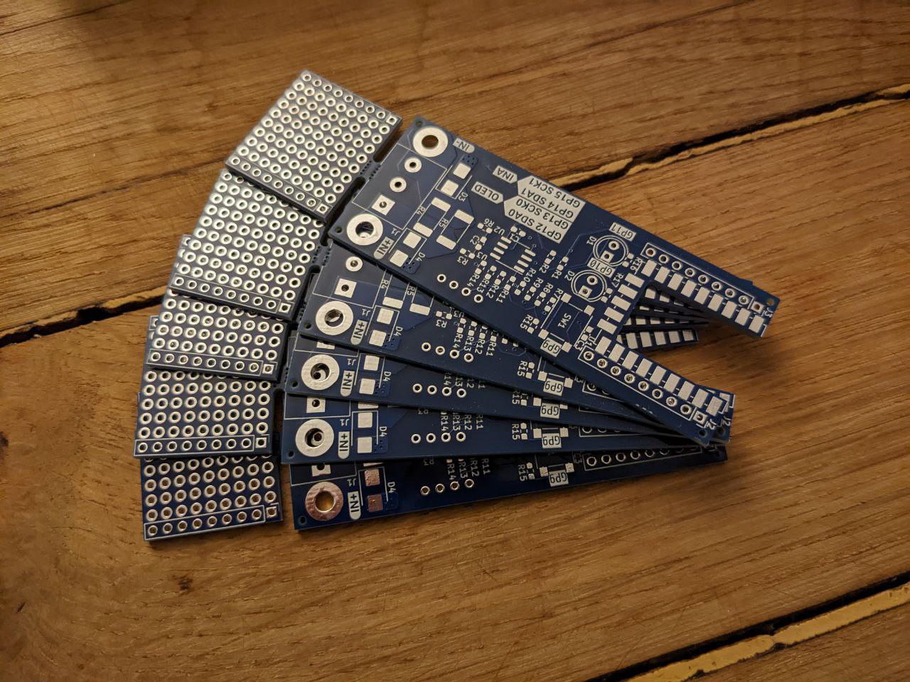


 Matthias
 Stephen Harrison
 Bob Baddeley
great project, there is a lot of need for power and voltage meters at industrial sites. I work at a plant where we want to reduce energy usage. It would be great if there would be an open hardware IOT device which can measure current or voltage and sent it to the cloud Just current could be helpful as well. The idea is that you can sent people a message to turn of a device that shouldnt be on or seems to be not functioning. Imagine that current is too high for the device being off and too low for thw device being working.