 Savo
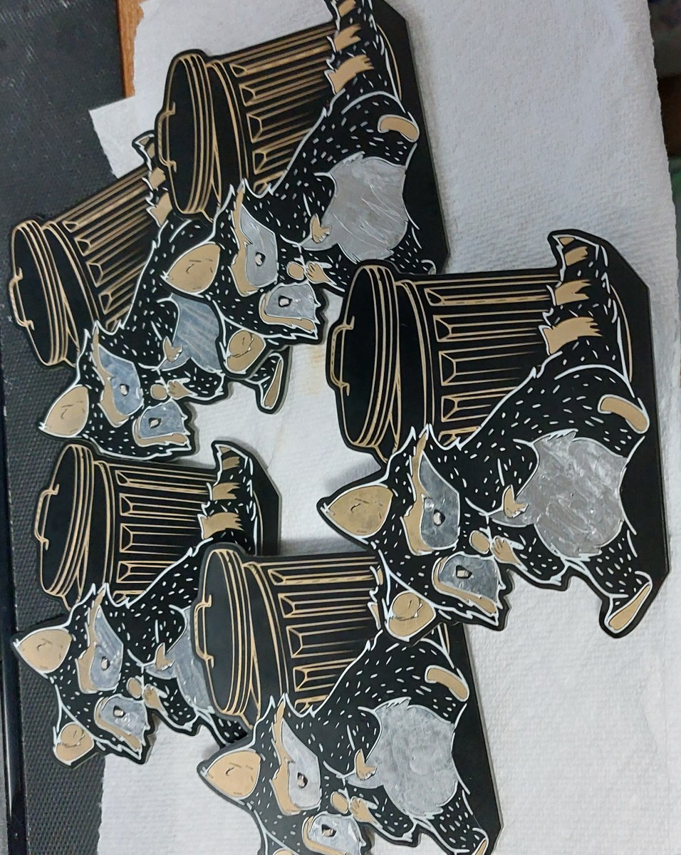
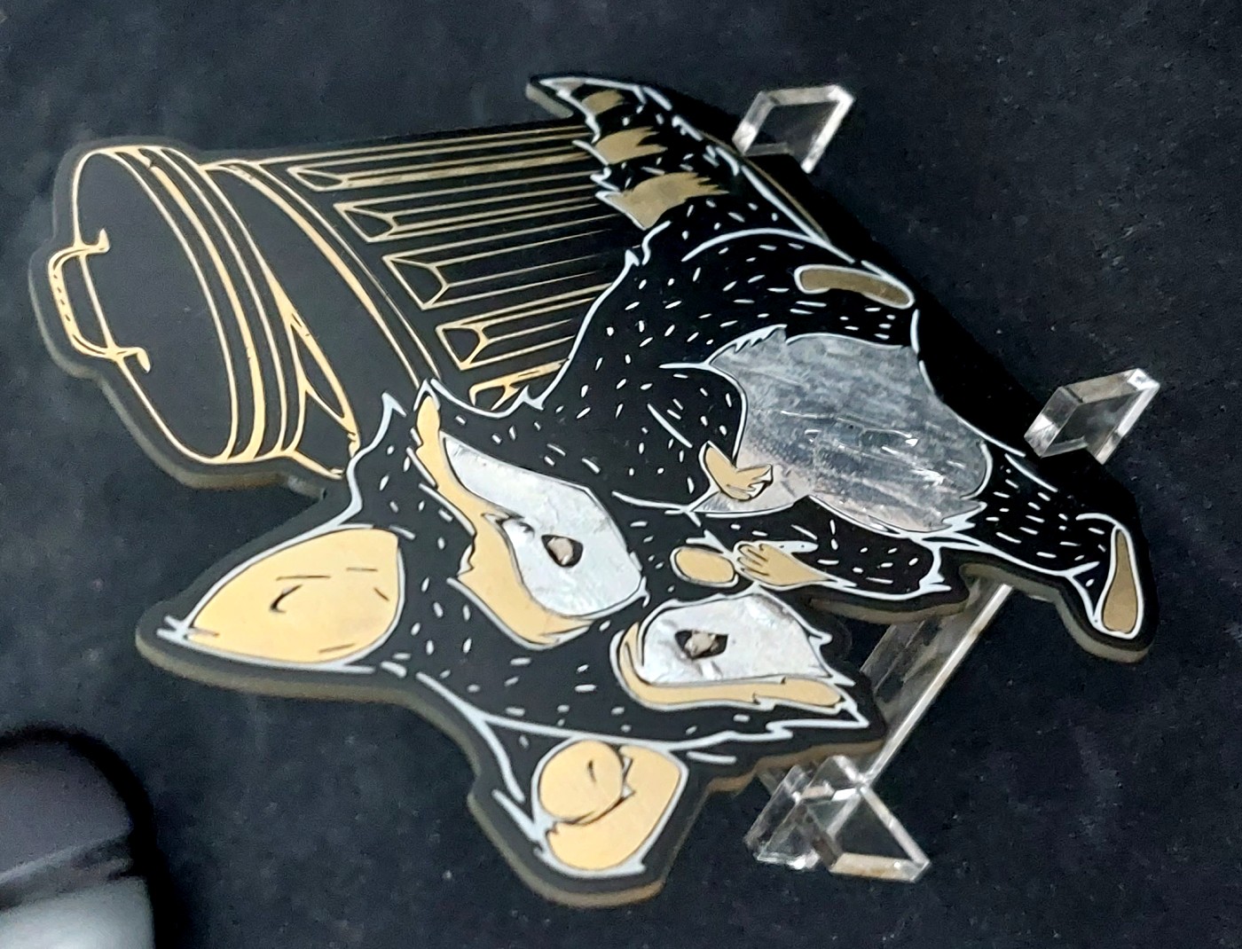
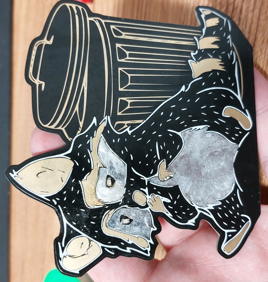
SavoI wanted to make a small circuit gift for some friends and family. My main consideration was that it had to be flashy and easy to explain so my non-engineering mother would be able to show it off, so blinking lights it was. As for a nice design though I decided to go for a raccoon since some of my friends really like them and its a nice homage to my home of Toronto. Combining the two I got this idea for a raccoon with illuminated eyes.
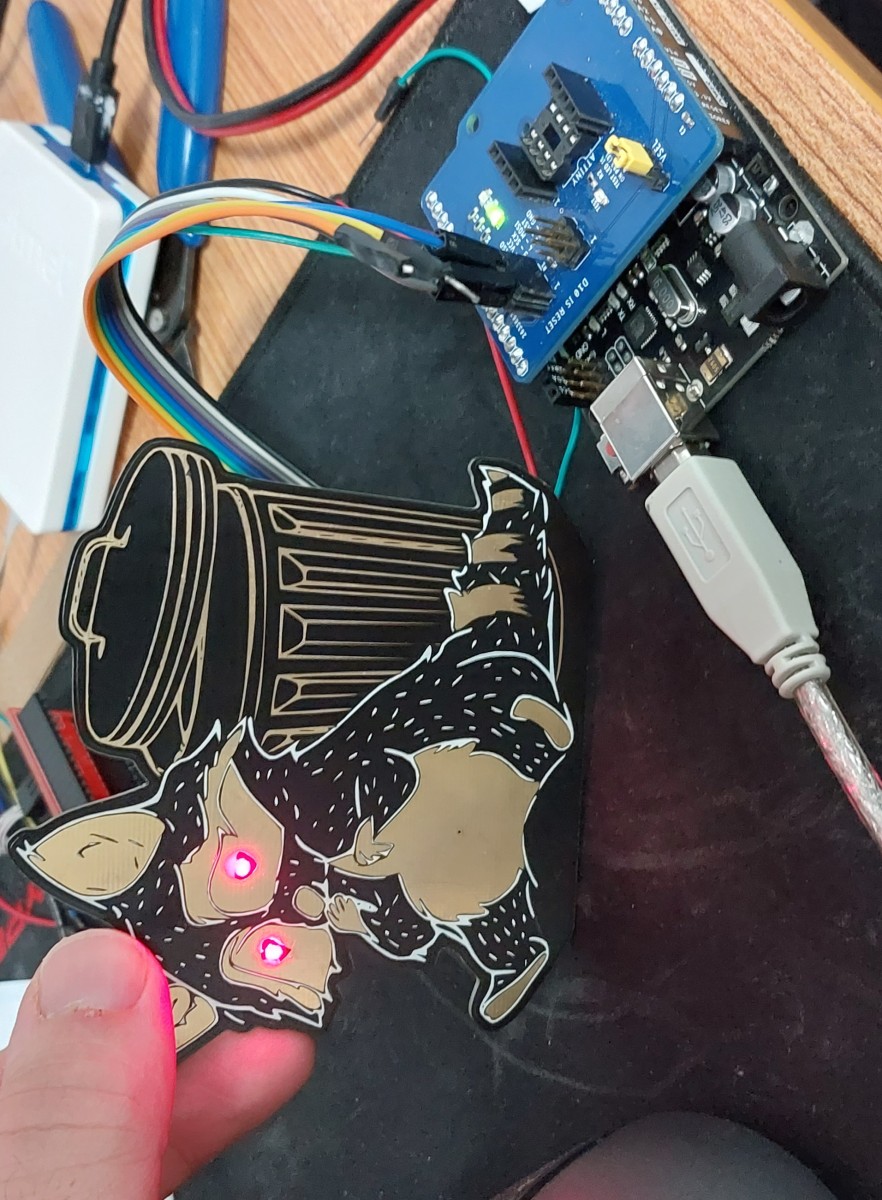
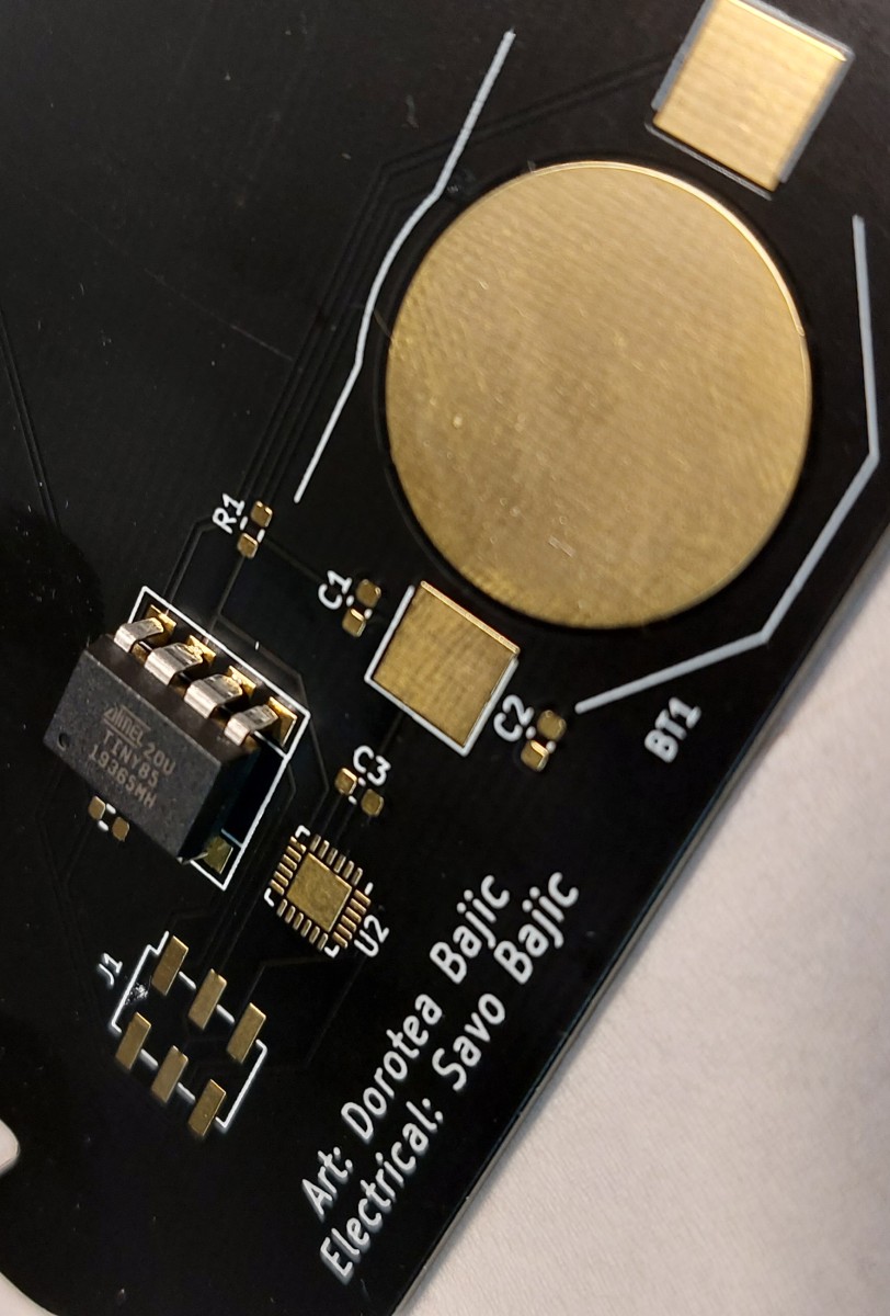
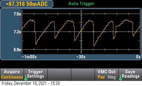
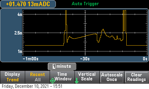
To get it to work I didn't want to have to buy any new chips since there was still a drought of most microcontroller I was used to using, so I decided to use the ATtiny85s I had laying around that seemed to have very good low power consumption and the potential to do some capacitive sensing! To get the system running required a minimal amount of code really, although it took me a while to really get the power consumption as low as I could without greatly sacrificing functionality.
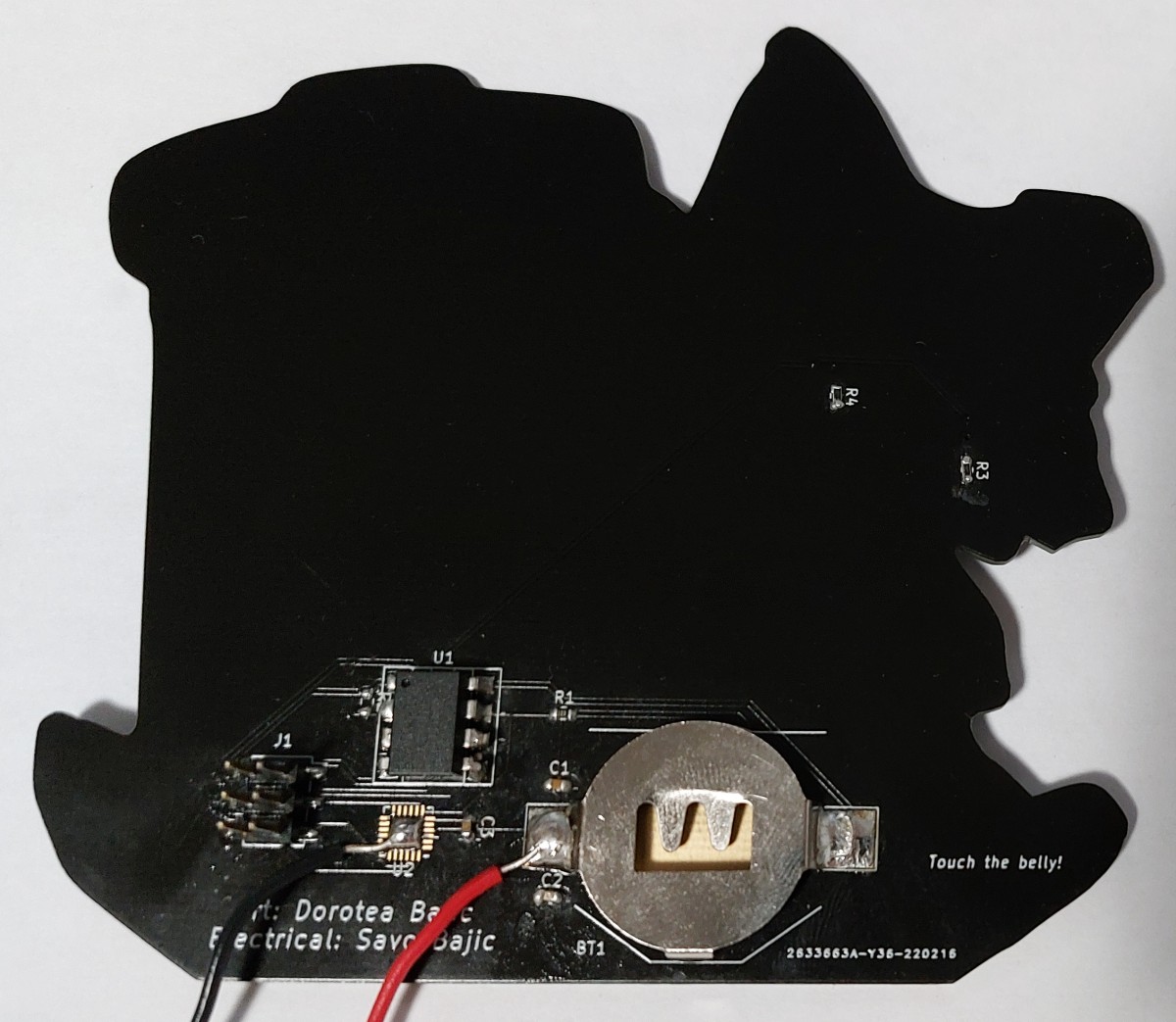
The circuit is quite simple, and the board my first attempt at PCB art. I think my sister's artwork came out quite nicely after I imported it into KiCad.
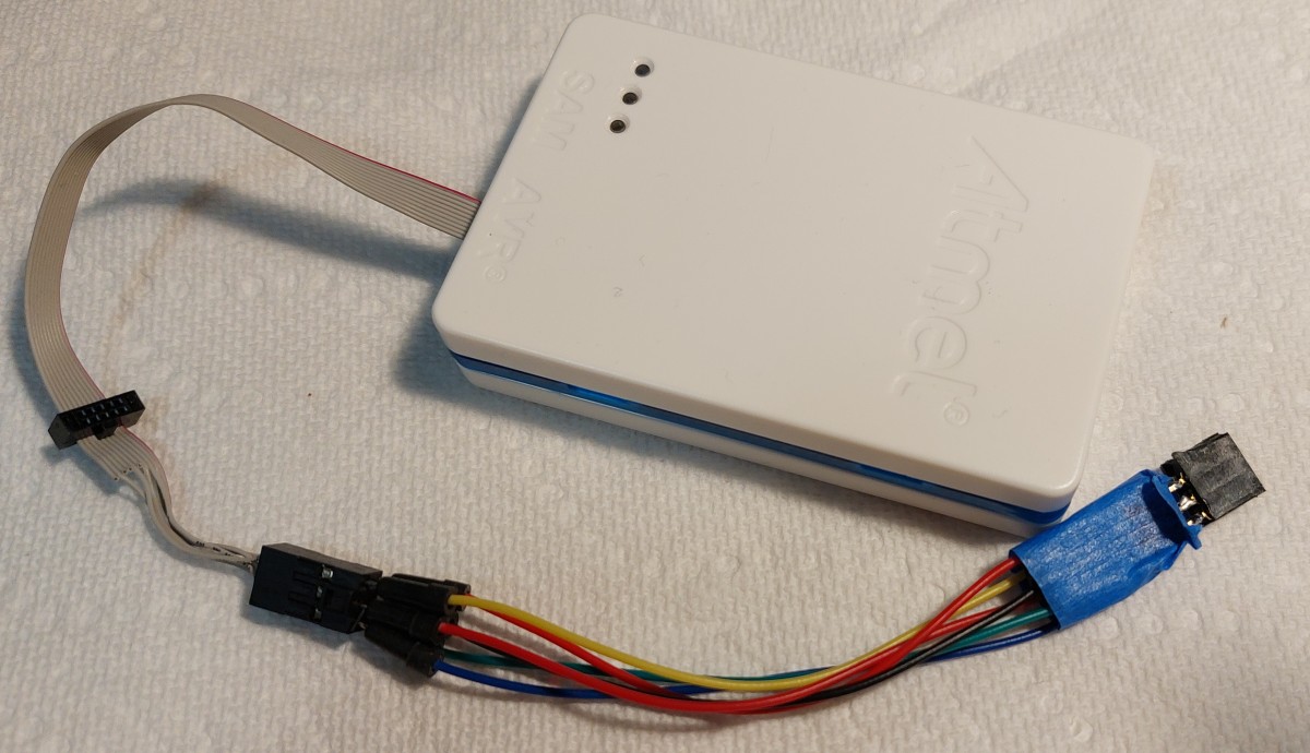
Assembly was easy and programming required little reconfiguration on the final boards.


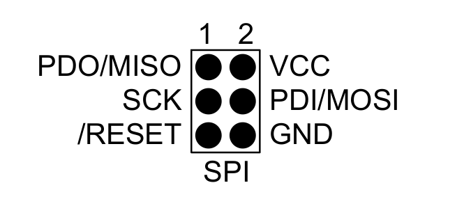


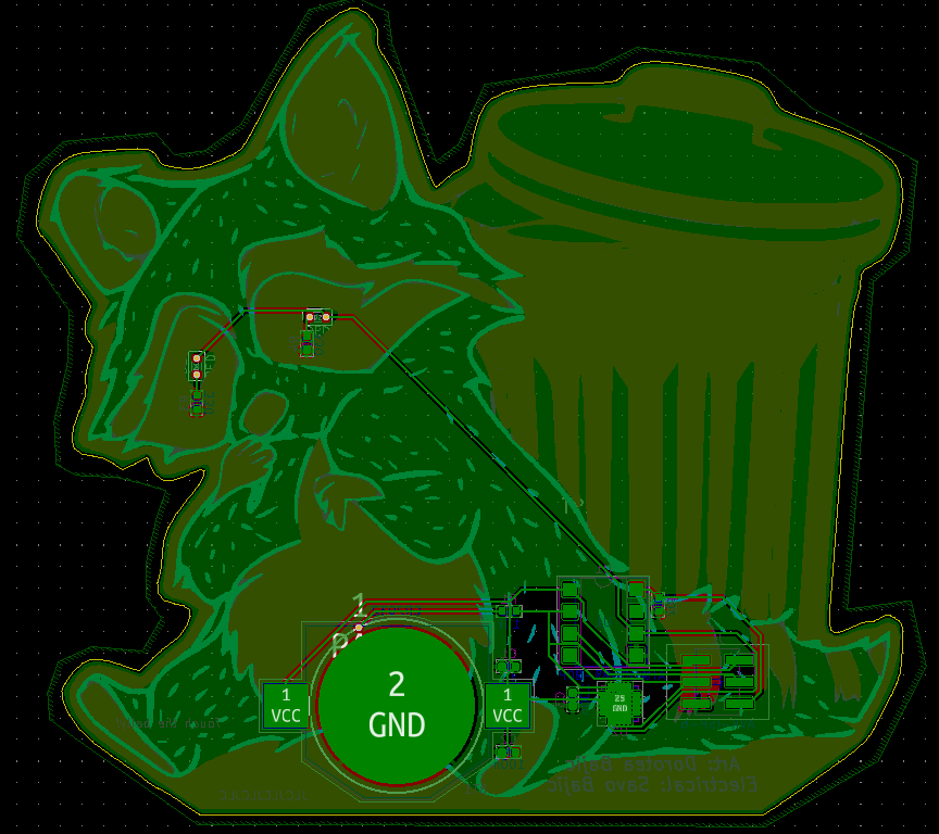
 Schematic for the raccoons
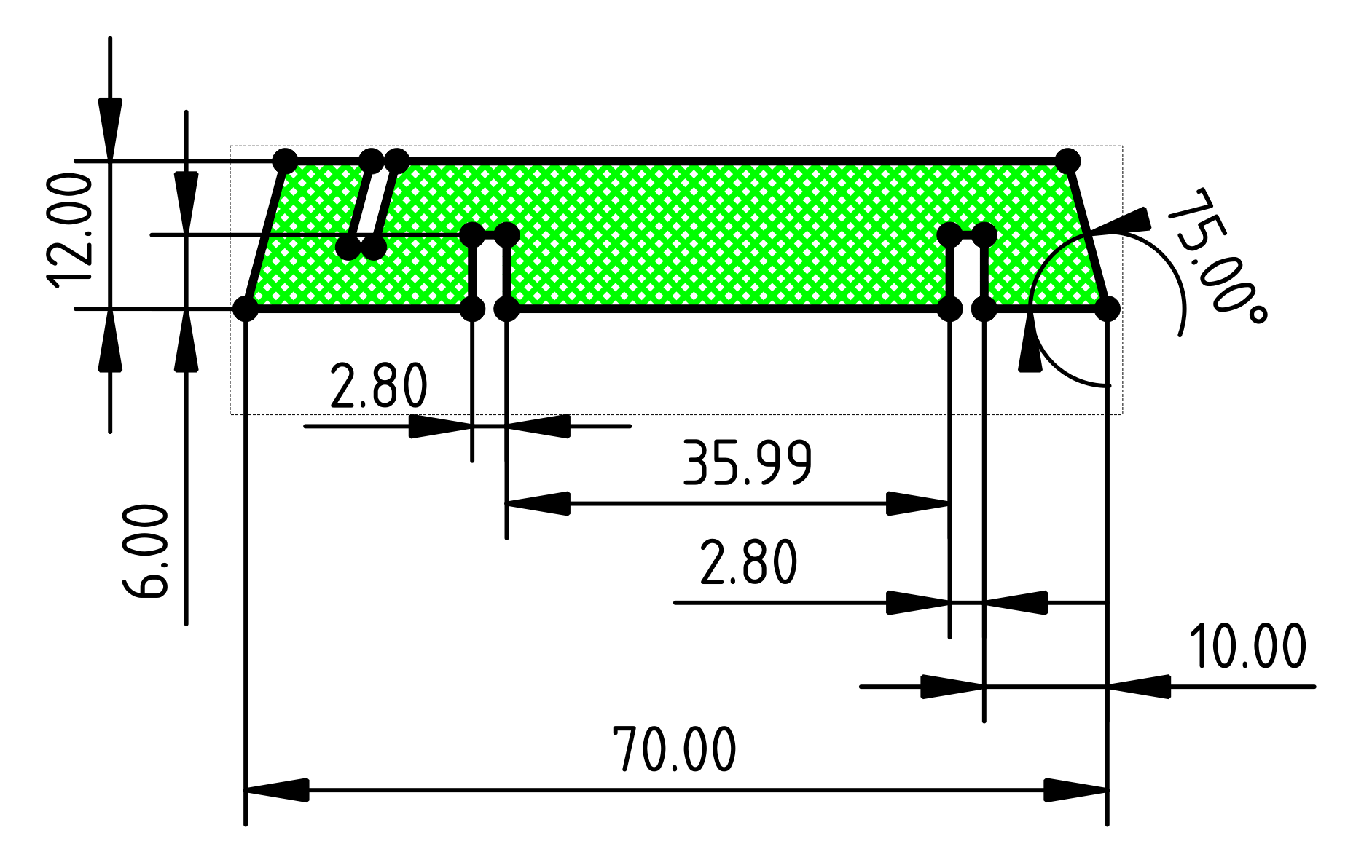
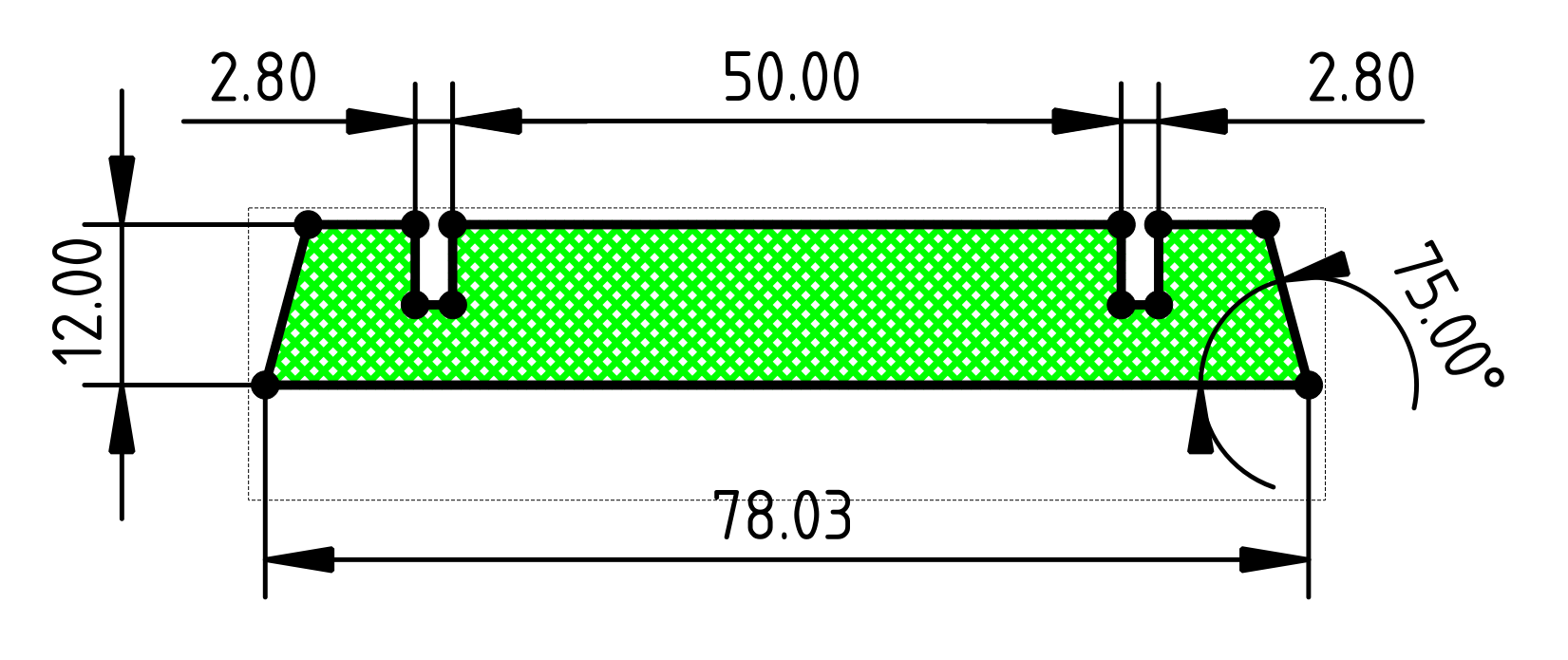
 The base image, with a green outline for the edge cut.


 Andy
Andy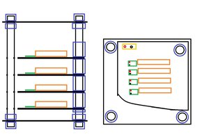
 cyplesma
 Jon Kunkee
 Pinski1