 Matthias Hasenfus
Motor/Servo selection
In my search for a suitable motor I came across the HBS 880 BB MG
brushless servo.
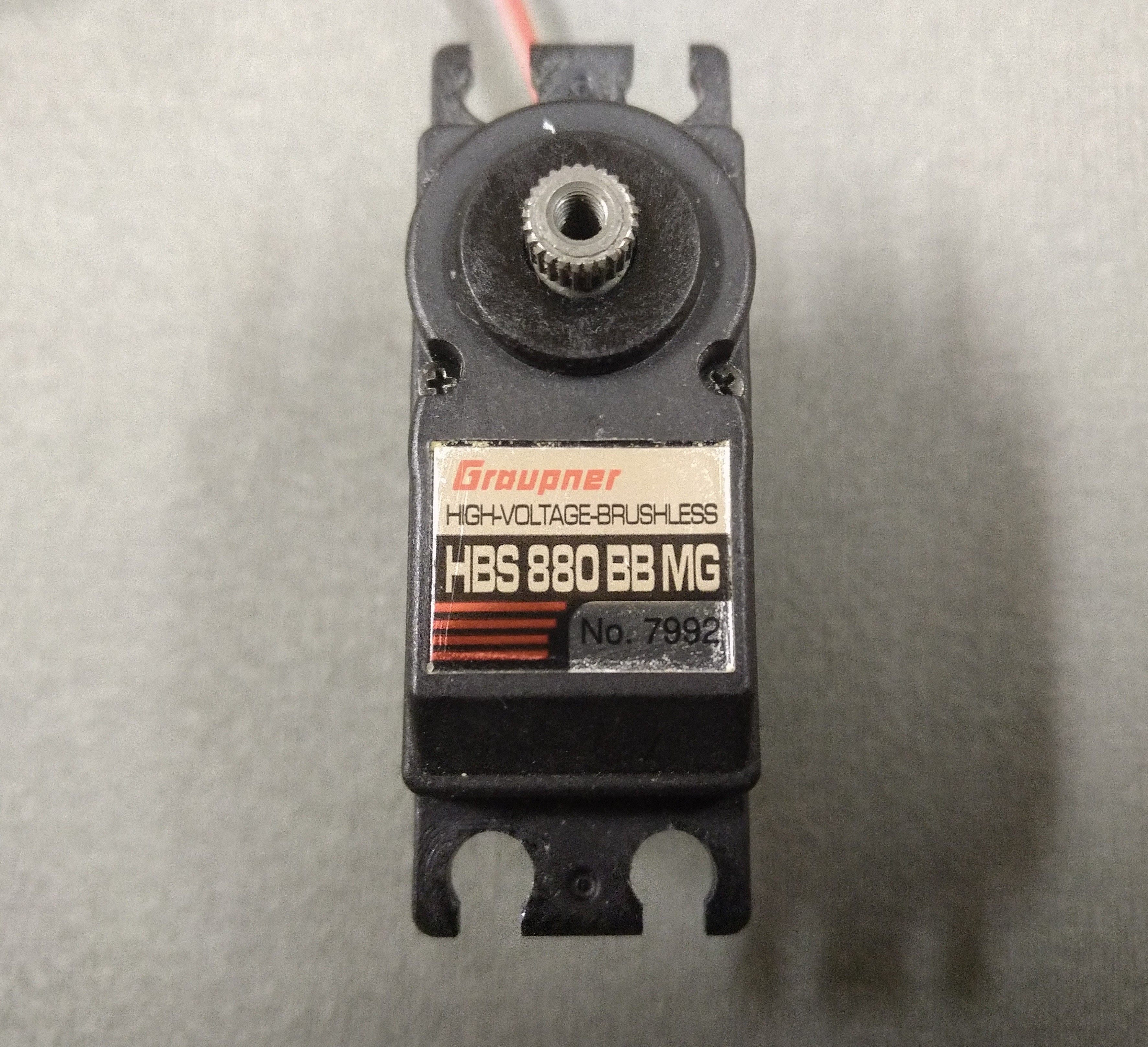
Hobby servos are a good fit for this project since they are relatively cheap, lightweight and already include a gear train. Also the splined output shaft can double as filament drive gear. This particular servo has the following things going for it:
- Brushless (no brush wear and we can use the commutation sensors for control feedback).
- Partially metal gear train.
- 2 ball bearings on the output shaft (we will apply some lateral force after all).
- 1Nm at 7.4V (that’s 333N on the 6mm output shaft, the filament would probably slip earlier).
- 140rpm at no load conditions (enough for 40mm/s retracts).
- 70g (I measured it at 64g).
I was unable to judge if this servo can easily be converted to continuous rotation so I just bought it and found out.
Continuous rotation modification
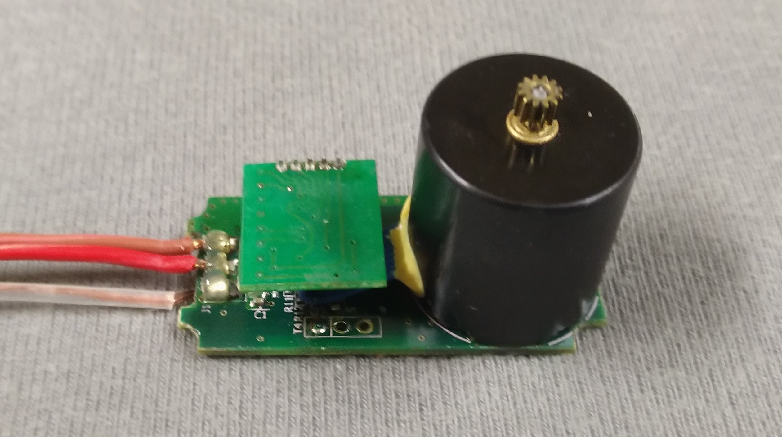
This Hobby servo is quite easy to open up. After removing the 6 visible screws it can be pulled apart. The feedback potentiometer is no longer needed so I simply cut the wires. Now is the first time we see the motor its a mere 17.4mm in diameter and 18mm in length. The three motor phases are soldered directly to the PCB. The wires for the hall sensors go to a little daughter board.
But what we care about now is the gearbox. It comes apart as 4 gears nicely spread across the workbench. I took the liberty to reassemble it for the photo.
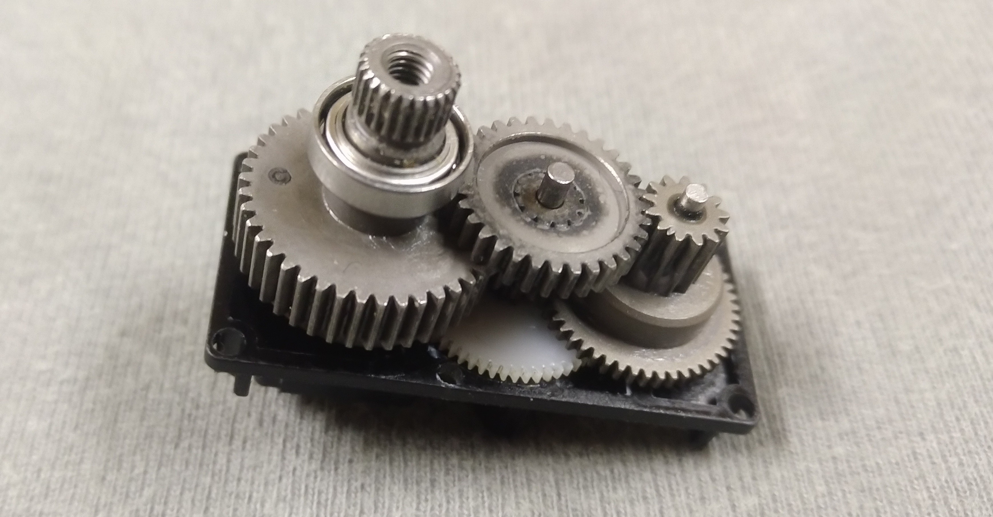
The only things keeping the output gear from rotating 360° are the potentiometer and a small pin embedded in the final gear. The potentiometer can easily be pulled out after unscrewing the single fastener holding it in place.
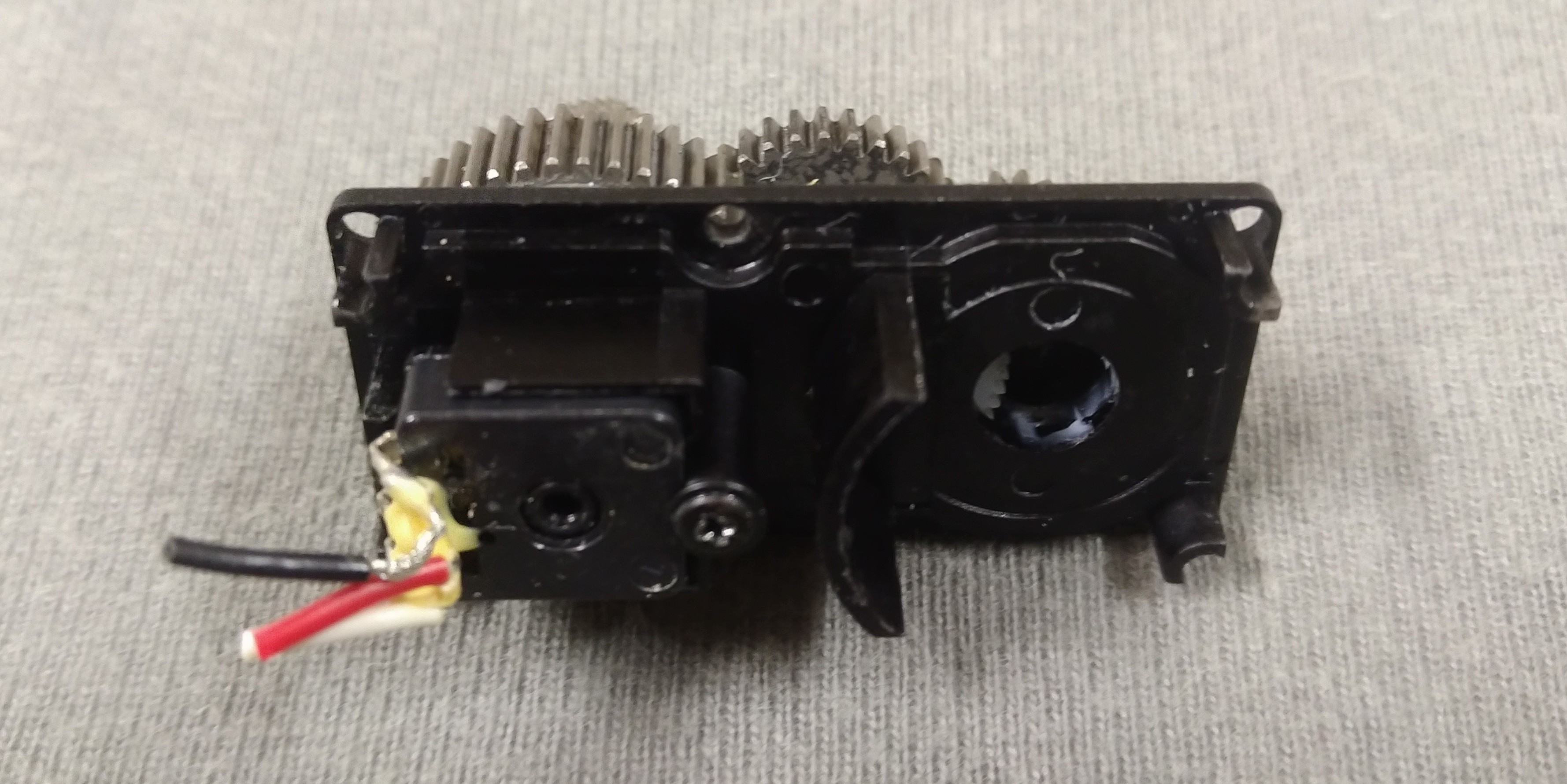
Pulling the pin from the gear didn’t work so I used a saw to cut it
off. A file works for removing any remaining unevenness.
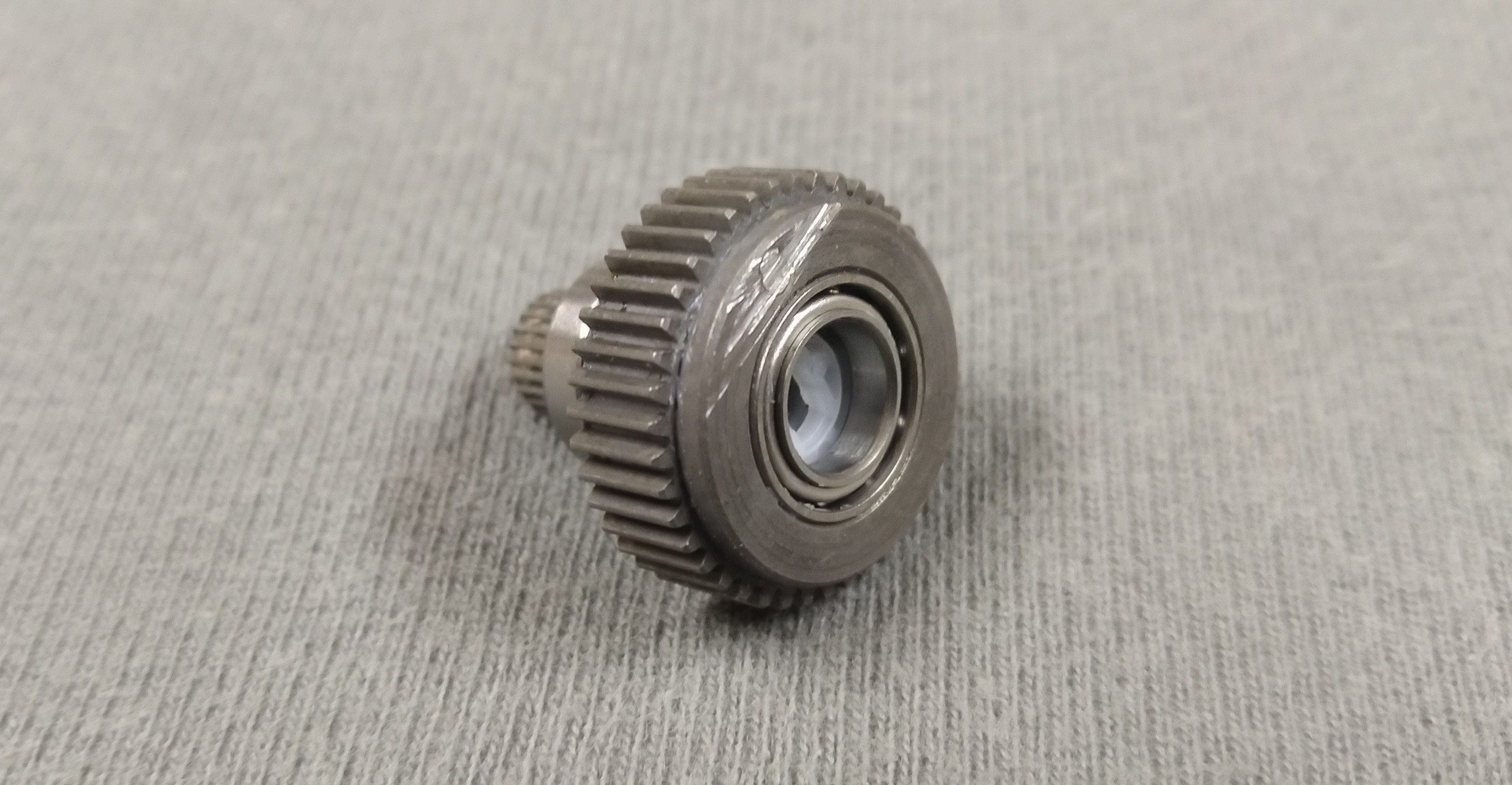
About now I notice that one of the ball bearings doesn’t run as smooth as expected. Rolling the output shaft across an even surface reveals the likely cause. It is slightly bent. Oh well, no refunds at this stage so it will just have to do for a prototype.
PCB modification
Besides the BLDC motor and gearbox the hobby servo also comes with
the necessary electronics to drive it, so why not reuse the
electronics as well? The central part of the servos electronics is a
PIC33FJ32MC202 digital signal controller. To the left of the image
are the MOSFETS and associated driver circuits. The row of five
header pins at the top connects to the small daughter board that
handles the signals from the hall sensors used for commutation.
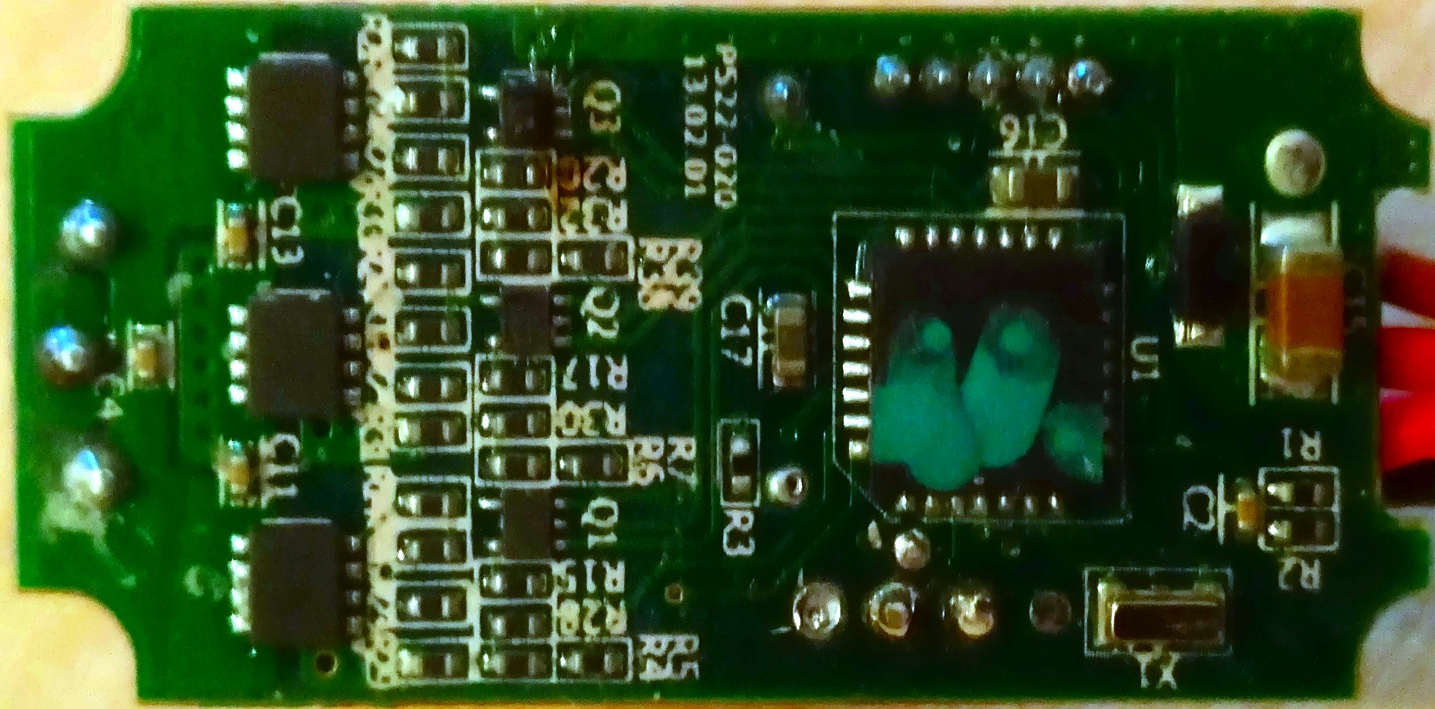
Learning to work with a new microcontroller is outside of this projects scope so I decide to remove the QFN packaged device and hook into the IO signals. With a little probing while the microcontroller is still in place I manage to figure out the signals.
With some hot air the QFN package is easy enough to remove. I use enamelled copper wire to connect to the IO signals and the potentiometers 3V pad. Thin heat shrink tubing works to keep the wires together. I recommend applying a bit of tape over the solder joints for some basic strain relief.
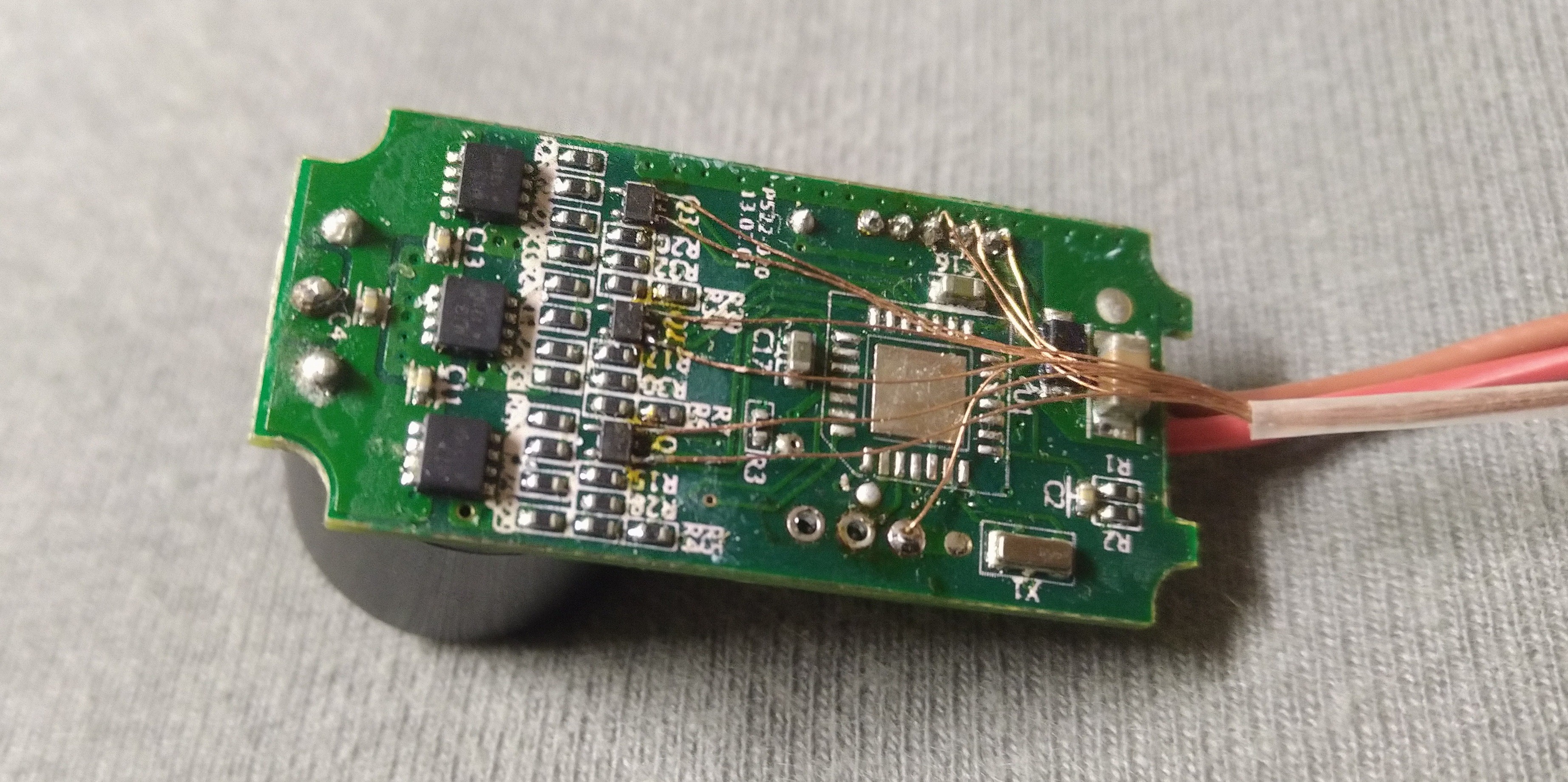
A simple connector is fashioned from a row of pin headers and some tape. By poking the pins trough the tape and then folding the tape around onto itself a nice handle is formed that keeps strain off the copper strands.
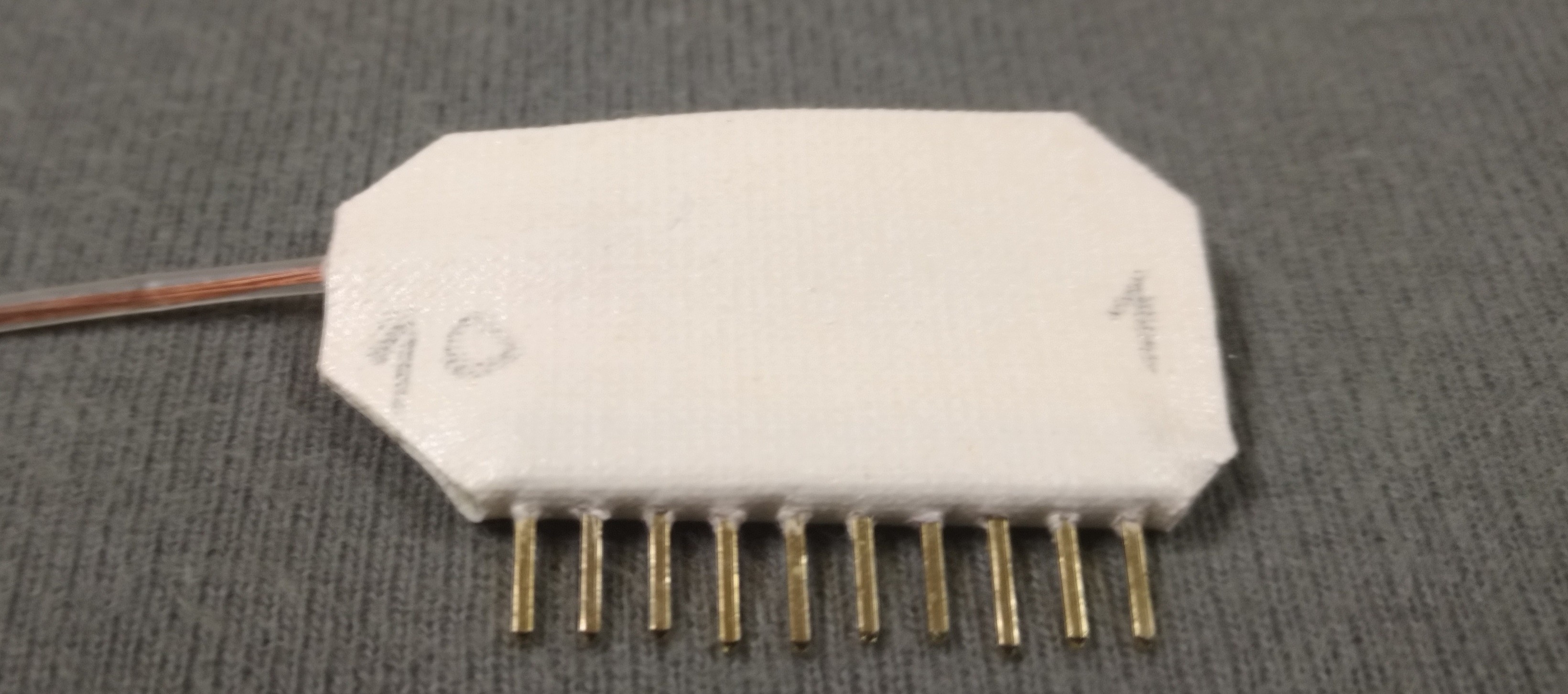
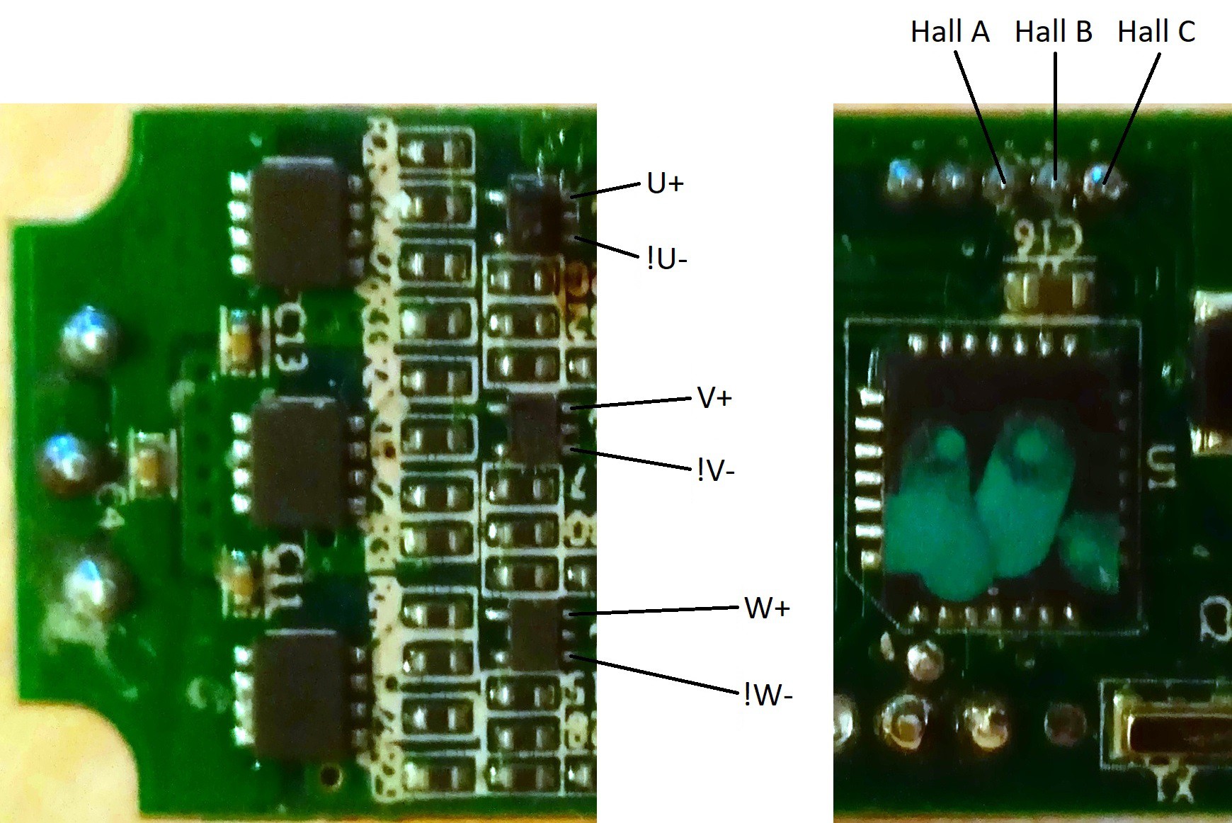
Here is the pinout I decided on:
- 3V_out
- Hall_C
- Hall_B
- Hall_A
- U+
- !U-
- V+
- !V-
- W+
- !W-
The servos usual signal input wire is no longer needed. Removing it frees up enough space to get the new wires outside the housing besides the two power leads.
BLDC motor commutation
So how do you make a sensored BLDC motor run? Here are links to some nice appnotes on the subject:
Please be aware that the commutation tables in those appnotes do not apply universally though. The pahse shift of the hall signals can be 60 or 120 degrees and some of your signals might be inverted. In my case all the low side drivers take inverted signals. I have...
Read more »
 Saul
Saul
 A.M. Smith
 Ossum
Ossum
 shane.snipe