 mircemk
This time I will present you an interesting way to use the PCB board from an old CFL bulb to make some useful electronic devices. As we know, these bulbs are no longer in use, so we can buy from the remaining stock for a very low price. I bought 24 watt CFL bulb for less than $2.
I noticed the genius idea these days at the Zafer Yildiz channel and immediately decided to make some kind of device with a CFL bulb electronic board. We can remove the PCB relatively easily with a screwdriver.

Next we need to release these wires coming out of the glass tube. So, this is the PCB that has been removed from the bulb:
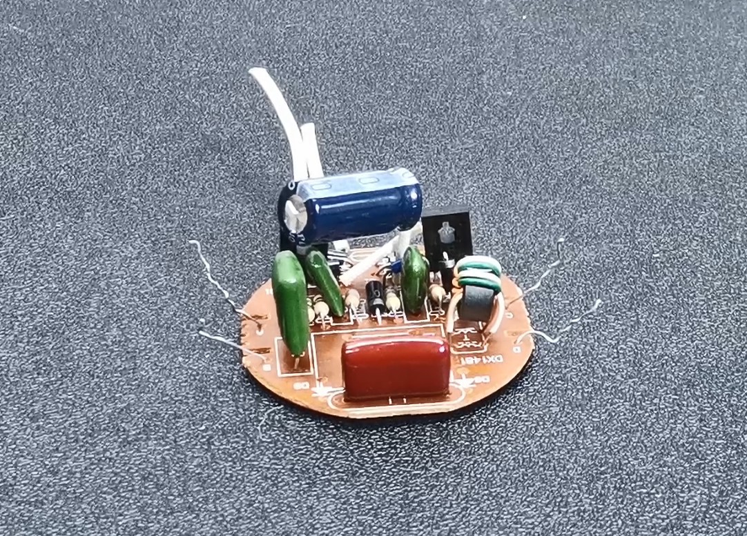
First of all, about the way of powering these bulbs. In general, the schematic diagram is the same for all types of CFL Bulbs and consists of several parts:
- A rectifier consisting of four diodes connected in a so-called Gretz junction with Filter Capacitor.
- A switching mode converter containing two transistors and a small toroidal transformer, usually with three windings.
- A choke winding that serves to limit the current and has the form of a standard transformer.
- And finally a glass tube filled with Mercury and Argon gas coated inside with Phosphor.
If you want to make a PCB for your project, PCBway is a great choice for you. PCBway is one of the most experienced PCB manufacturing company in China in field of PCB prototype and fabrication. They have a large online community where you can find a Open Source projects, and you can also share your project there. From my personal experience I can tell you that on this community you can find many useful projects.

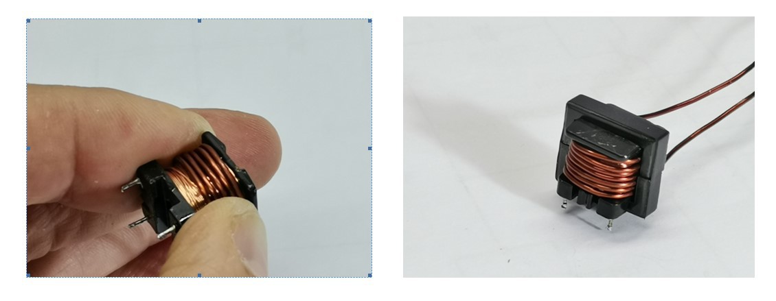
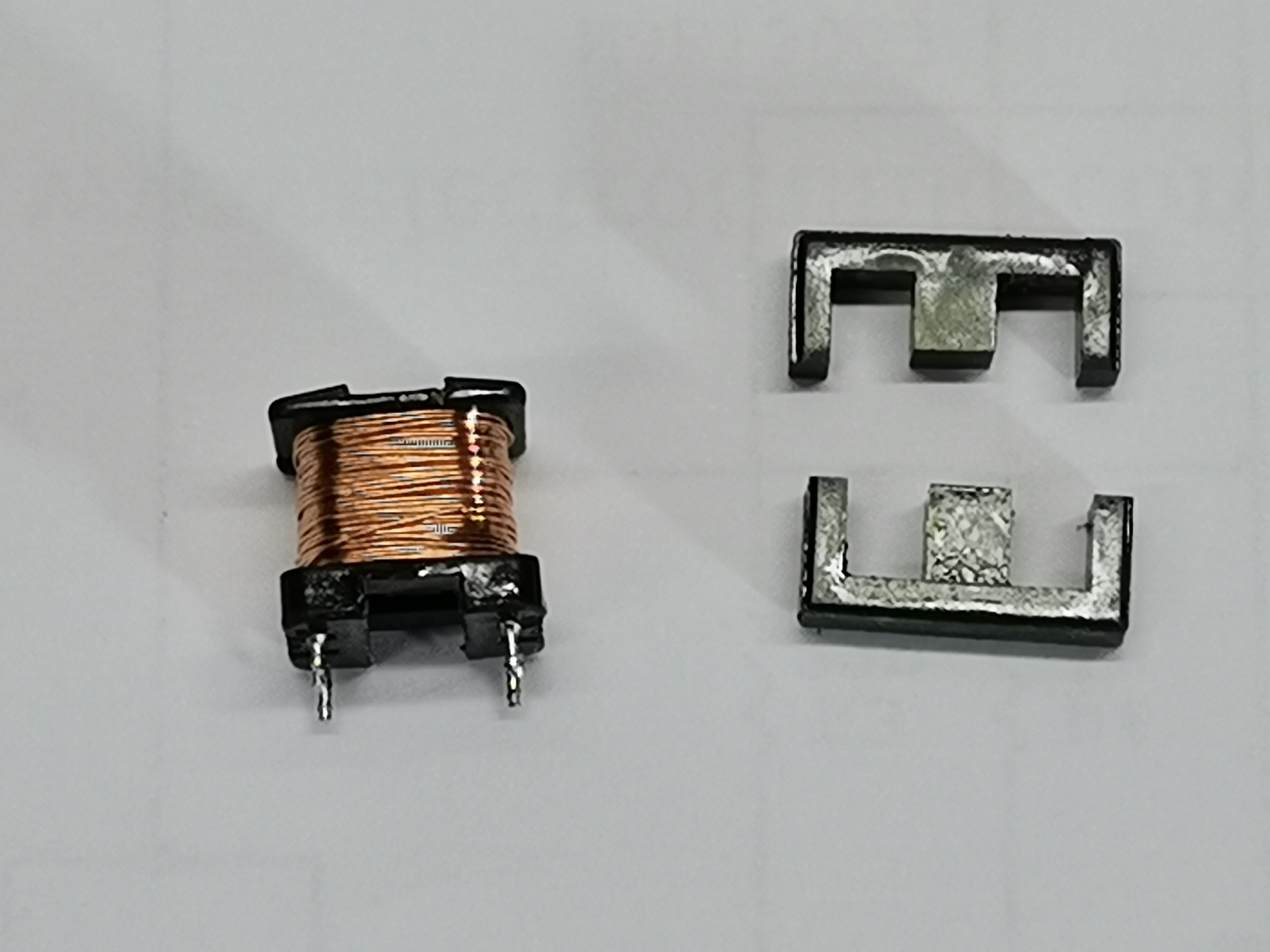
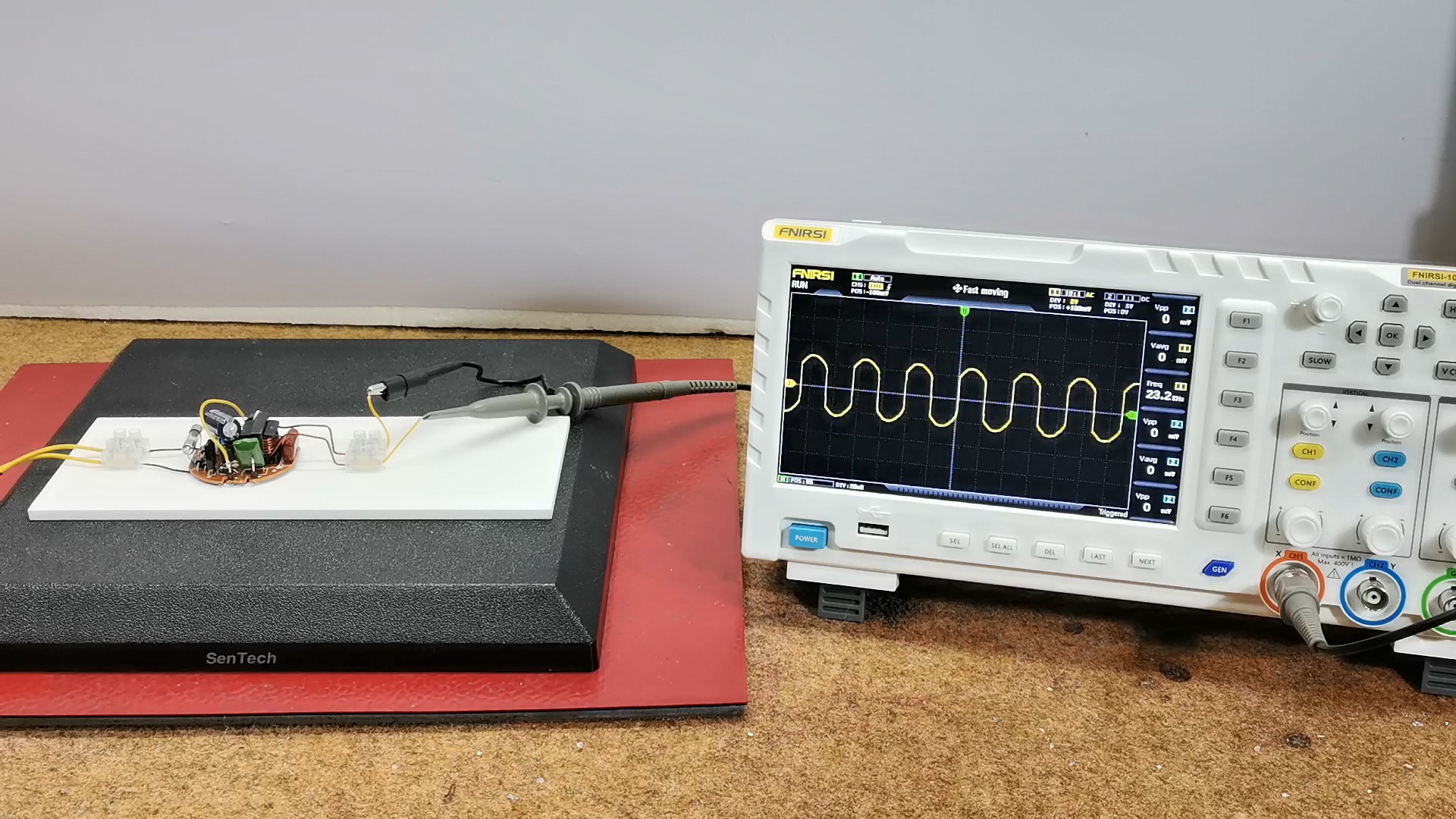
In our case, the most interesting is the Choke Transformer. It is very important to emphasize that all CFL power supplies, regardless of brand or wattage, contain this type of choke. When making any device, we can freely ignore the rest of the circuit and e will use the changing magnetic field created by choke coil. Our task is to wind a certain number of windings(about 7-8) with lacquered copper wire with a diameter of 0.8 to 1 millimeter, which actually represents a secondary winding.
Next, we need to short-connect these two wires in the first case, or short-circuit these two pairs of wires as the next option. In this first case, the switching frequency is lower.
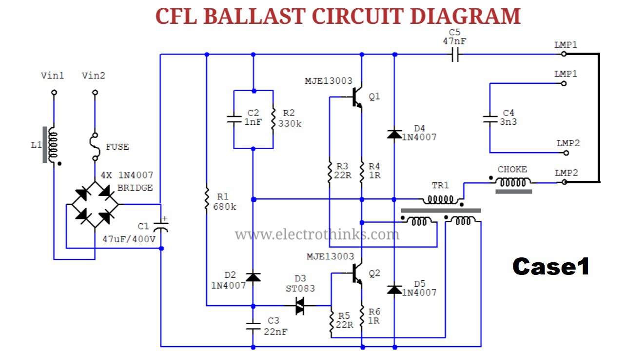
In the second case the two capacitors are connected in series, the switching frequency is higher. Unfortunately, the second connection method will be avoided due to the relatively high frequency of oscillation and the transistors may burn out very easily. This completes the part of modifying the CFL board. Let's look at the signal shape of the secondary winding that we just added to the choke transformer. The signal is almost rectangular, with curved edges, and its frequency is 28 kilohertz.
Now , the most interesting part:
To make an induction heater we need to wind about 10 turns of copper insulated wire on a body with a diameter of 6-7 millimeters and connect it to the previously modified circuit. Now we will insert the iron object inside the coil and it will heat up in a short time.
Next, to make a DC power supply we need to connect a classic rectifier consisting of a Gretz junction and an electrolytic capacitor. The output voltage is 10 Volts. We can also connect a battery charging circuit to the output.

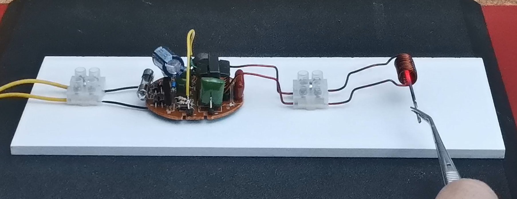
Finally we can make an high voltage source. For this purpose, we need to connect the primary of the HV transformer to our modified circuit. I was surprised by the fact that even after long-term operation of the circuit in this mode, the temperature of the transistors and the coil did not increase almost at all.
And finally, in conclusion, this is a really great way, as from an old CFL bulb, we can make more functional devices in a very simple way, but of course I would like to emphasize that even the most experienced DIYers should strictly adhere to the safety rules when working with high voltage.
SAFETY NOTE: Please do not attempt to recreate the experiments shown on this video unless you are familiar with High Voltage Safety Techniques! Direct Current even above 60V maybe lethal, even when the AC supply voltage has been disconnected due to the stored energy in the capacitors.