Sagar 001
I made a simple waveform generator using operational amplifier, here this signal generator can be used to verify the electronics circuits and small integrated circuits. It can generate square wave and triangular wave up to 5khz. The main reason to make this type of waveform generator is price, it can be made under $2. And requires very few components. The basic working of an operational amplifier type waveform generator can be found here.
Basically the triangular wave is generated using the square wave, whenever the step input comes it makes a ramp which is a RC integrator circuit. But the amplitude of triangular wave is directly depended on the frequency. If the frequency is high then the output amplitude is very less.
Because reactance offered by capacitor is more in the case of low frequency comparable to high frequency. This is a fully analog type of waveform generator; you can design the same with any operational amplifier having good slew rate. Then we will design a PCB for square wave and triangle wave so that it is easy to get those waves and to reduce overall noise. JLCPCB is China based PCB manufacturer and offering 5pcs of 2 layer PCB in just $2. To know more offers on precision layer PCB visit official webpage from here.
Sine wave:
The sine wave can also be generated using the same technique, if we add one more integrator to circuit then the ramp of triangular wave changed into parabolic type shape which gives sine wave. But the effect of amplitude is very much depended on the frequency. So these type of waveform generator are useable below 1khz and has pretty good advantage because of minimal components and price. That's why the other good circuits like Wein bridge and hartley oscillators are used.
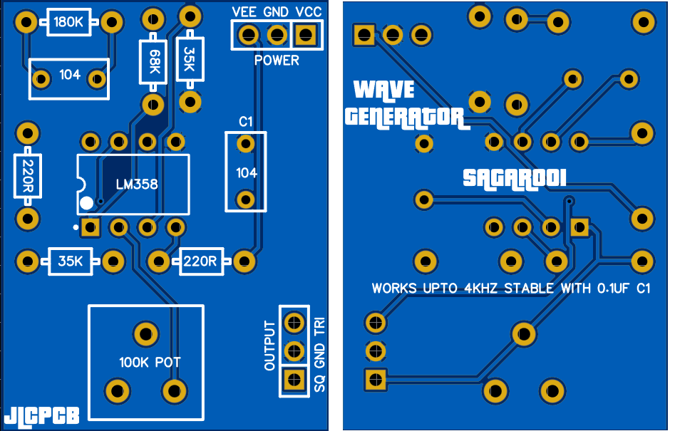
Circuit diagram:
The circuit diagram of square wave generator is very simple, basically a 3 resistor 1 capacitor configuration is used. R1 decides the charging/ discharging time of the capacitor time and a voltage divider of R2 and R3 is used to give the appropriate base line to waveform known as ground line(middle level). Hence a proper controlled waveform can be generated using this. The value of capacitor and resistor R1 decides the frequency range of the waveform generator, and to get the variable frequency output we can make this Resistor variable. That’s why we use 100k potentiometer here.
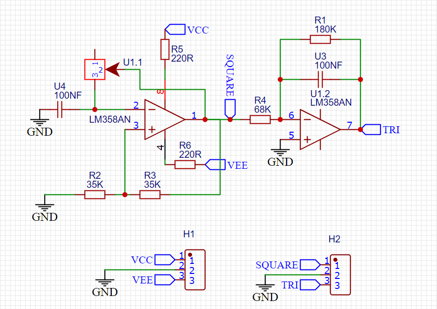
This circuit is able to produce square wave at high frequency also, now to get the triangle output an integrator is added in series with the output of square wave. And the value of RC integrator should be higher than the time period of the square wave. The value of R4 and C2 are chosen though. Keep one thing in mind at lower frequency the overall circuit reactance is low and keeps on increasing as the increase in frequency take place. So the output amplitude of triangular wave depend on the frequency. There will be not any change in the overall frequency while converting square into triangle wave.
Components required:
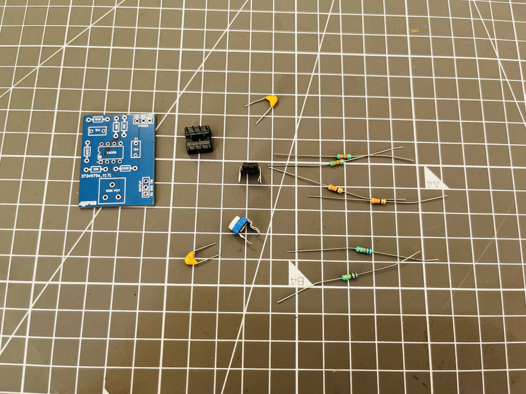
1) LM358
2) 180K, 68K, 39K AND 220R resistors
3) 100nf capacitor
4) 100k variable resistor
5) Dual rail power supply
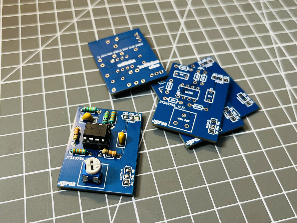
Gerber files and PCB design:
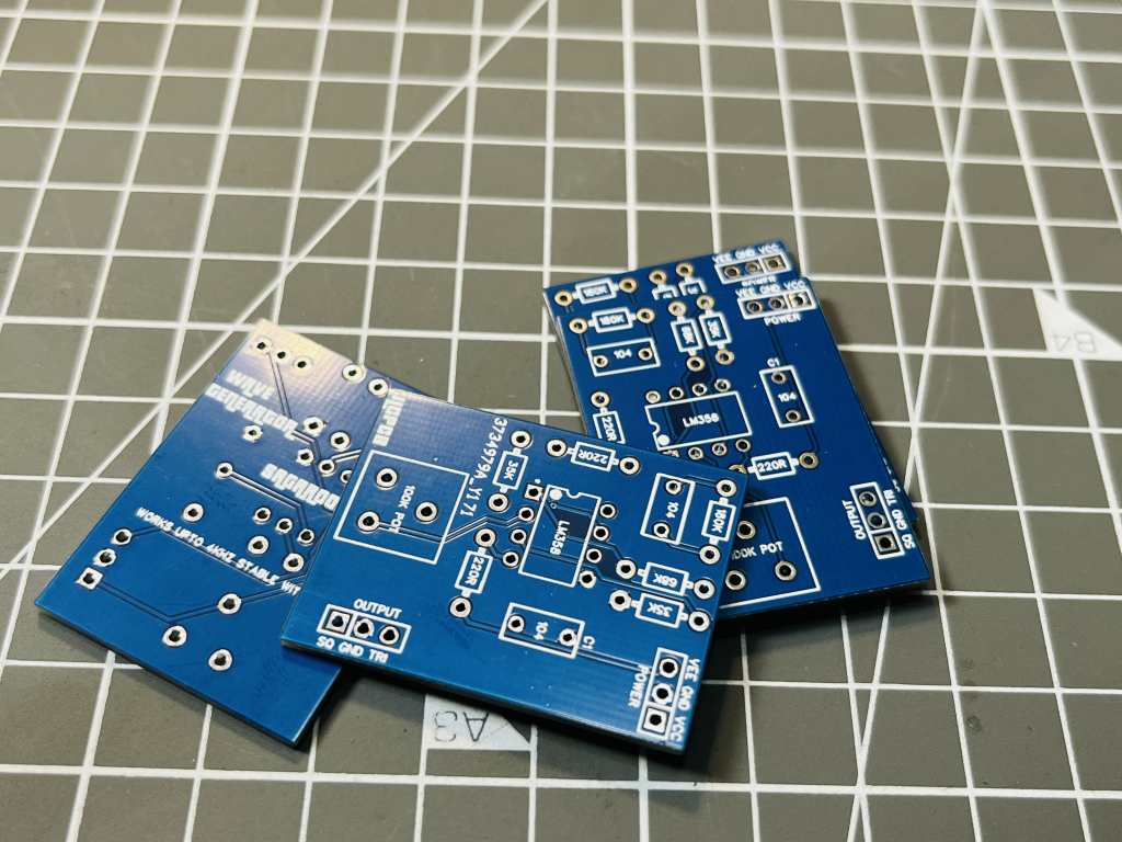
I designed these Gerber files in EasyEDA you can modify the files as per schematics or if you want a steady amplitude triangular wave then a extra gain setting is required with one more operational amplifier and you can download the Gerber files from here.
These Gerber files can be used to order the PCB from JLCPCB, JLCPCB is the leading PCB manufacturer company from China deals in PCB related stuff like PCB assembly, precision PCB and Stencil making. Sign-up now using this link to JLCPCB and get free coupons of worth $54. A one stop solution to all of your prototyping needs.
Working of waveform generator:
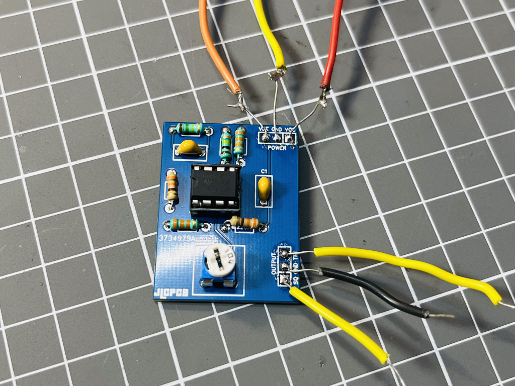
This PCB prototype is able to produce two type of waveforms and the frequency range can be selected via the capacitor and tuned with the resistor.
For square wave:
For triangle wave:
The amplitude of the square...
Read more »
 ElectroBoy
 Lithium ION
 Sproket