 alberto nunez
DIY Wi-Fi sensor, no programming, no soldering required
Software no-code/low-code platforms made it possible to create applications, writing only a few lines of code, and in some cases, ¡no code at all!. This reduces development effort and deployment time.
This project combines two ideas: no-code/low-code software platform and a quick, robust prototyping system that requires no soldering. In this spirit, it is possible to move from an idea, to a materialised device working in a real environment in a few hours.
Key component: ESP 32 D1 MINI
Quick, robust hardware-software prototyping
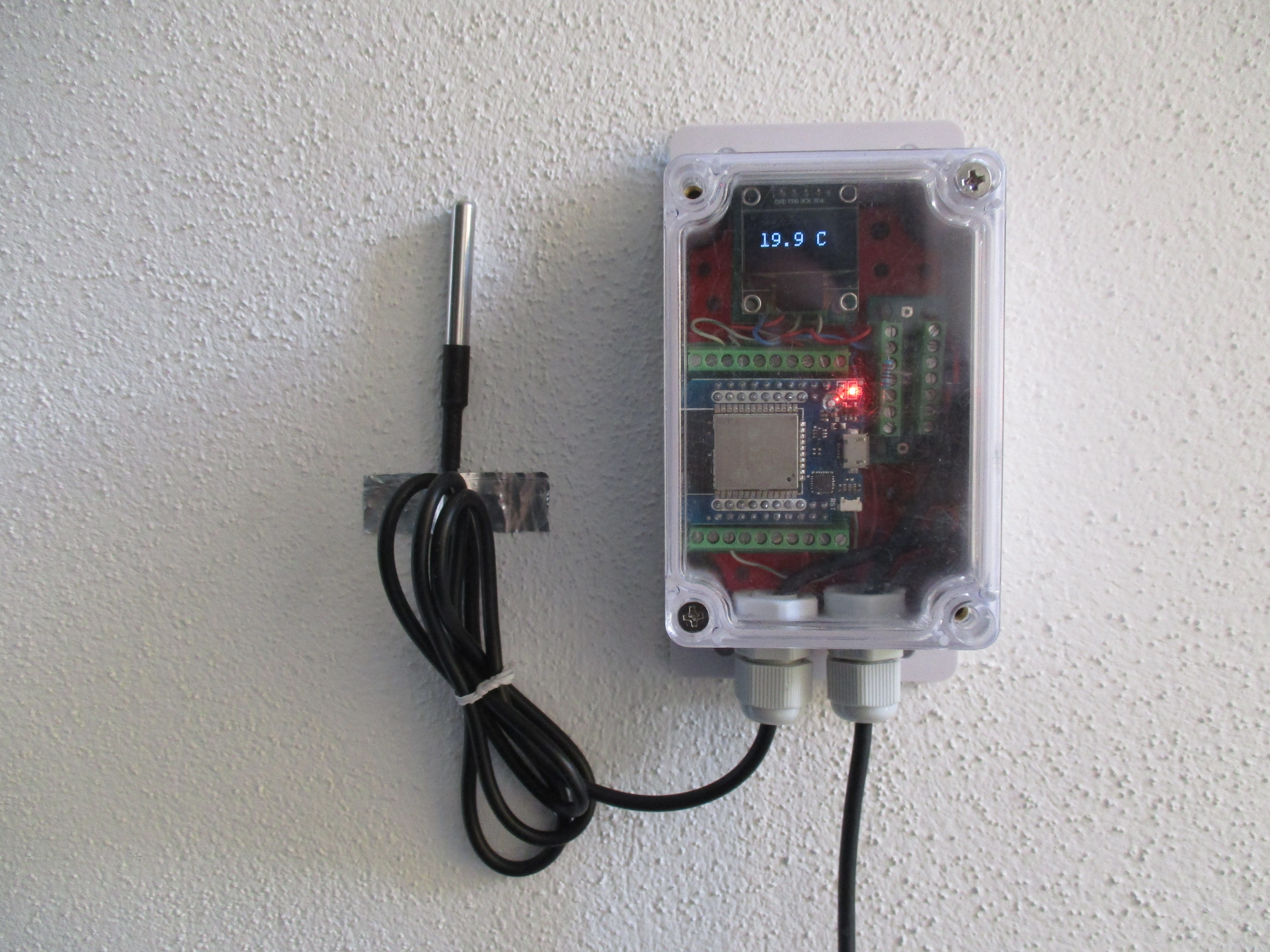
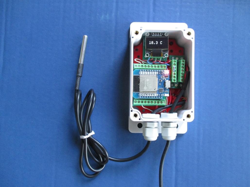
The following application will be built as an example: a WiFi thermometer based on ESP32, DS18B20 temperature sensor, and local I2C indicator. All this enclosed in a waterproof, wall-mountable box and powered by 5V. This will be accomplished using the following projects:
- HARDWARE: Quick, Open Source, robust prototyping system: MISISTEMITA
- SOFTWARE: Tested TASMOTA and also ESPHome.
Bill of materials
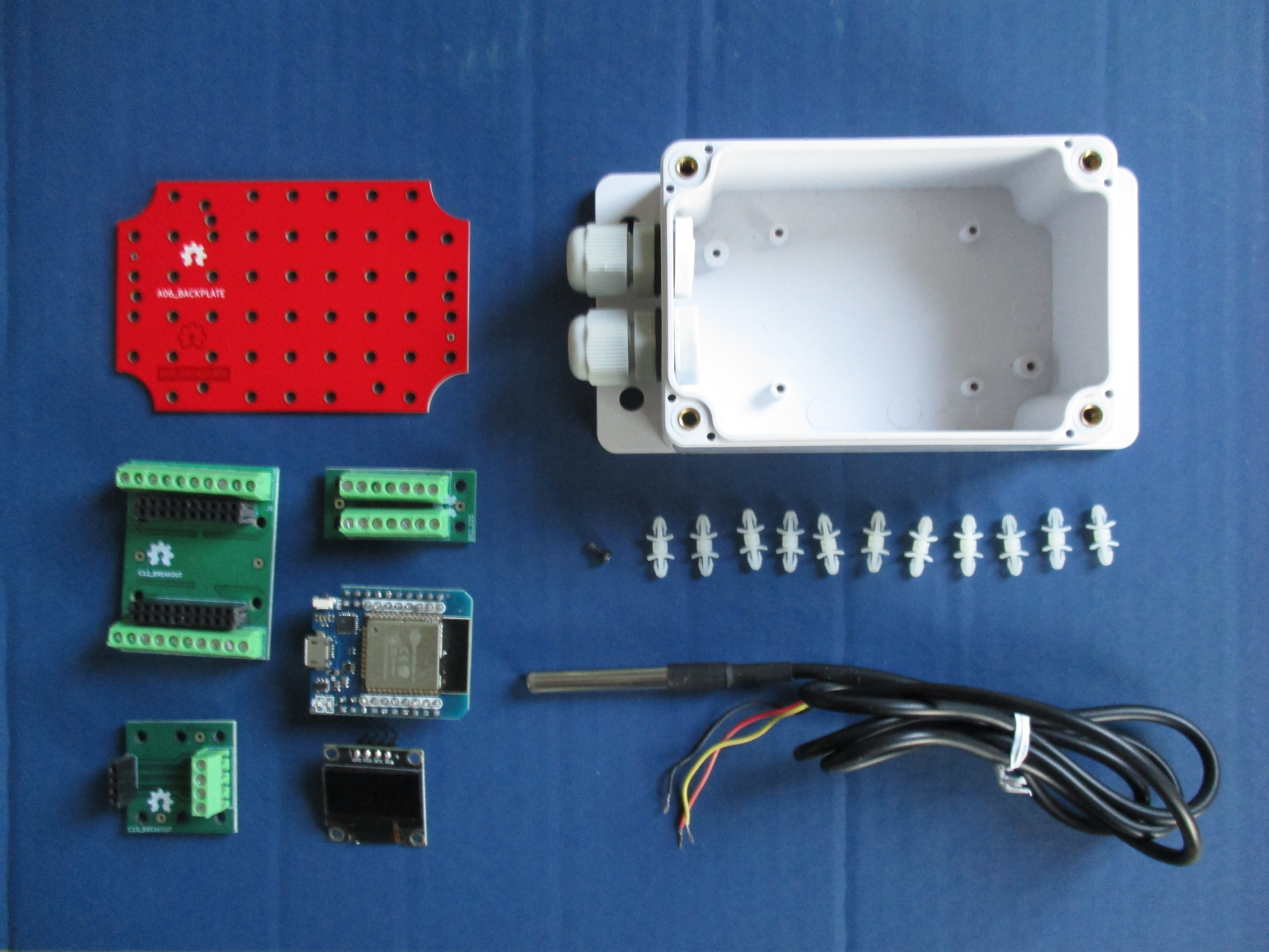
Discrete parts needed.
Component Datasheet - Buy link.
- ESP32 D1 MINI - buy it
- OLED 0.96 I2C Display - buy it
- DS18B20 waterproof temperature sensor- buy it
- 1/4W 1% TH Resistor- buy it
- Generic waterproof “Sonoff” enclosure 100x68x50mm - buy it
Components needed to build the required misistemita modules.
Component Datasheet - Buy link.
- Reverse locking nylon spacer - buy it
- M2.6 B-type self-tapping screw - buy it
- 3.5mm kf350 screw terminal (2,3 pins) for PCB - buy it
- 2.54mm female header connector - buy it
Printed circuit boards needed to build the required misistemita modules
PRINTED CIRCUIT BOARD SOURCE FILES REPOSITORY - BUY LINK
- A06 - Backplate for generic waterproof 100 x 68 x 52 mm enclosure - buy it
- B02 - 3.5mm screw terminal 2x7 connection board - buy it
- C12 - 3.5mm screw terminal breakout for ESP32 D1 MINI - buy it
- C10 - 3.5mm screw terminal breakout for I2C display - buy it
SOFTWARE REPOSITORY - DOWNLOAD LINK
Hardware assembly
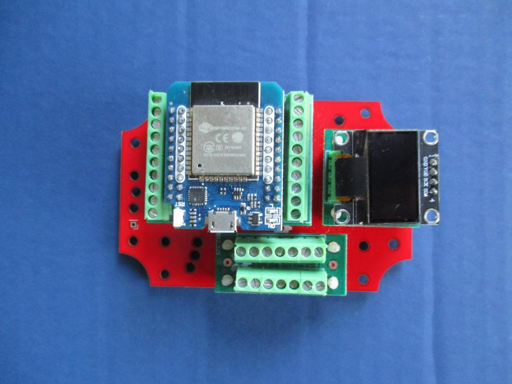
Soldering will not be required* if the modules to be used have been built or acquired beforehand. The first step is to locate the boards in the backplate, as good practice, the screw terminal wire connection boards should be placed somewhere on the edge of the backplate and as close as possible to the cable entry point.
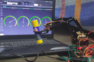
The second step is to wire the different modules depending on the originally proposed project. Both solid copper cable and multi-stranded copper cable can be used. Downloading a minimum test firmware is recommended to test the connectivity of the components.
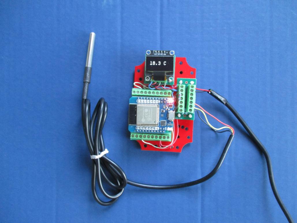
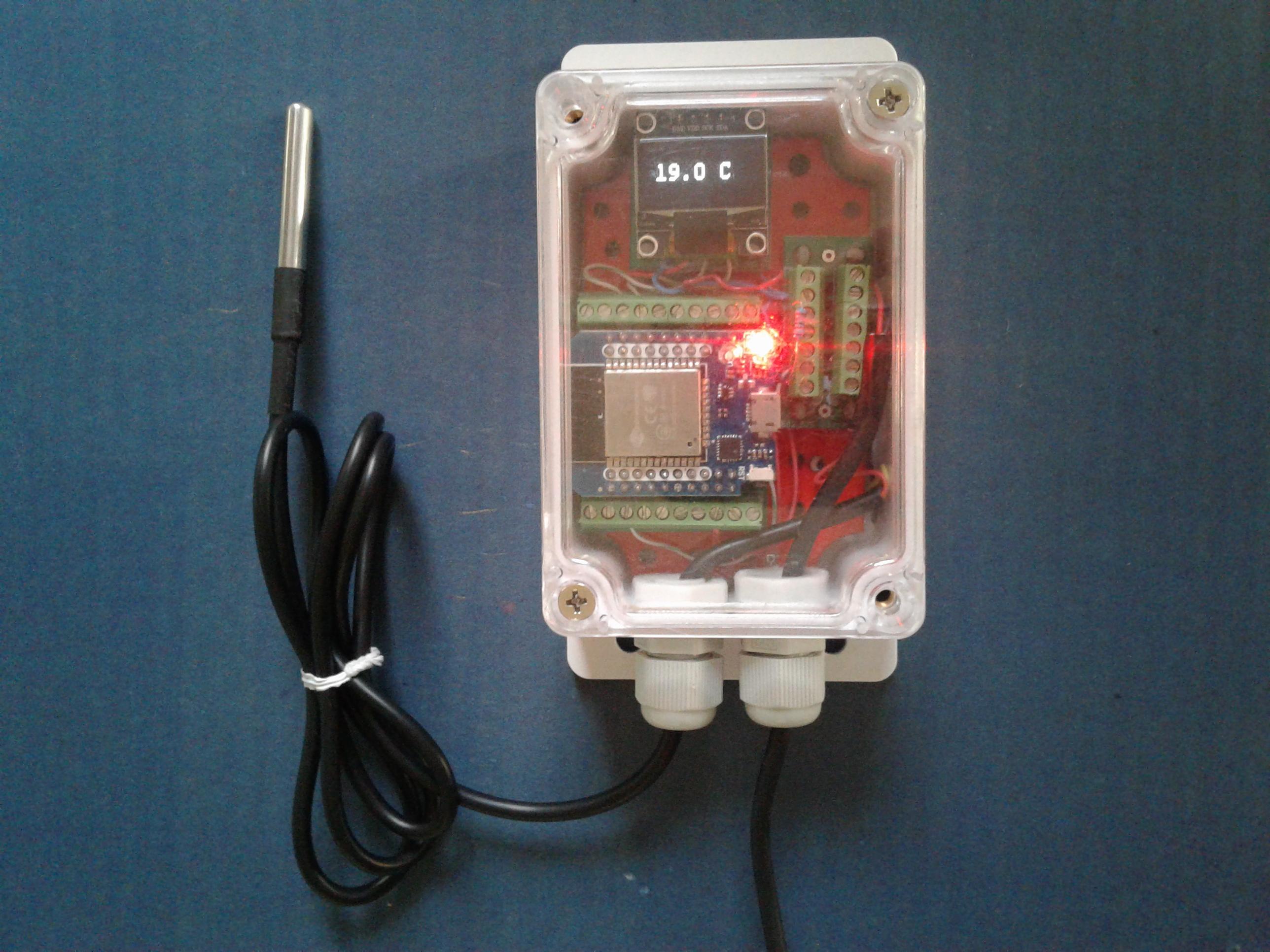
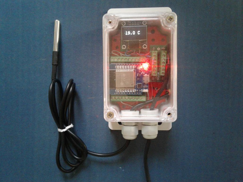
The third step is to remove the external connections, locating the backplate in the enclosure and securing it with self-tapping screws. Pass the power cables through the cable glands and reconnect them to the board.
The final step consists of closing the cover, adjusting the cable glands, and installing on the wall.
Firmware setup
The following points are not intended to be a comprehensive installation or configuration guide. For more information, refer to the documentation of each platform used, (Tasmota and ESPHome). Briefly, some hints about how the sensor was created on each of them will be presented.
Tasmota
The philosophy of Tasmota consists of a basic pre-compiled firmware that is downloaded to the device and once downloaded it is customized using templates. The Tasmota installer is based on a web browser, so no additional software is required. The following parameters were used:
- Base Firmware: Display...
 cabalist
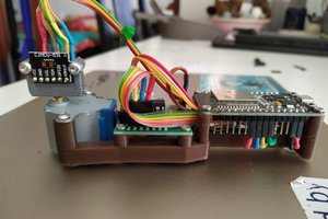
 Owen
Owen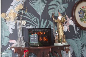
 Jithin