 Thomas
The anatomy of a CRT television
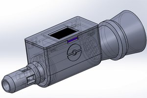
For this project I'm using this small 5" black-and-white television. It has the brand name "Crown" stamped on it, but this design is ubiquitous and can be found under many other brand names. It is one of the last generations of small CRT televisions ever produced—you can check out this short YouTube video for an overview of this model. It is wonderfully well-suited for maker projects, primarily because of its small size and power requirements: it can operate on either AC and 12V DC power. Some of these units have a composite input, and for those that don't, it's possible to modify the board to accept an external video signal, though we won't be using such a signal for this project.

Another nice feature of this model television is that the board is exceptionally well-labeled. Not only does each component have an ID number, but many of the capacitors and resistors also have their value marked on the board, which is rare in consumer electronics. I haven't been able to find a schematic yet for this device, so knowing these values will be particularly helpful if repair becomes necessary.

The concept behind CRT technology is wonderfully elegant. An electron gun at the back of the tube shoots a stream of electrons through a vacuum towards the screen at the other end. The inside of the screen is coated in a phosphorescent layer that illuminates when hit by electrons. The direction of the stream is controlled by magnetic fields generated by horizontal and vertical deflection coils wrapped around the neck of the tube. These electromagnets move the electrons from left to right over and over again, repeating this line pattern down the height of the screen before starting over at the top. This happens 50-60 times per second, fast enough that the human eye cannot detect anything other than a solid image. (If you want to see this concept at work, check out what a CRT television screen looks like when filmed in extreme slow motion.)
Discharging the tube
Before you go poking around inside a CRT, you must discharge the tube. For this you can use a long thin screwdriver connected to ground. I use a jumper wire with alligator clips that I clip onto the ground pin of a power outlet. If the TV is plugged in and has a ground wire, you can also clip the screwdriver to the metal frame holding the tube into the chassis, as it is likely connected to this ground path. Once you've grounded the screwdriver, slip the tip under the rubber hood of the anodethat attaches to the tube. You must contact the metal conductor under the hood. You may hear a pop or see a spark, and this is good: it tells you that you have successfully discharged the tube. More often than not, however, you won't see or hear anything—that's normal, just be sure you make contact with the metal under the hood. The capacitors on the board itself may also be holding a charge, so be careful when handling it.

Desoldering the wires for the horizontal deflection coil
There are four wires that travel from the horizontal and vertical deflection coils on the tube's yoke to the TV's main board. Our goal is to disconnect the pair at the yoke that control the horizontal deflection, and in their place solder in two wires from our audio source. My TV was nice enough to label these wires on the board for me (V1, V2, H1, H2) so I would know which pair is for the horizontal deflection, but in most cases you will have to figure out on your own.

So how do we know which wires coming from the yoke control the horizontal deflection and which control the vertical? First you must use your multimeter to identify which wires are pairs. There are four solder points where the wires meet the coils on the yoke of the tube. Measuring with your multimeter in continuity mode, find which of these solder points have continuity: if two points are continuous, they make up one of the pairs.

To see which pair controls the horizontal output, you must...
Read more »

 Furrtek
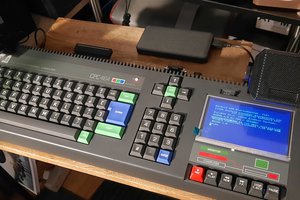
 Michael Wessel
 chrisprattmt
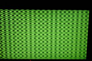
There has been a great deal of value to me in my involvement with the project. Would like to share it with the PIKASHOW APK DOWNLOAD team so they can also read it and implement something new.