 M. Bindhammer
A cyborg is a living being that has been technically supplemented or enhanced. It is thus a manifestation of human enhancement. This serves the increase human possibilities and increases human efficiency and thus the improvement and optimization of humans. Furthermore, by my own definition, a cyborg must have at least one bio-feedback in both directions that provides the cyborg with a superhuman ability.
I have chosen the head and thus a mask because most senses are located in the head and almost all important biomedical parameters can be measured at the head. Secondly, man has been using masks since the beginning of mankind. The oldest mask found is about 11,000 years old and comes from Israel. Remains of stone or metal masks were found - but drawings show that less durable materials such as cloth, plants, feathers, leather, or papyrus were also used to make masks. Masks are worn for very different reasons. For example, in the days before plastic surgery, masks were the best solution for veterans with faces scarred by war. And last but not least, almost every superhero or superheroine wears a mask.
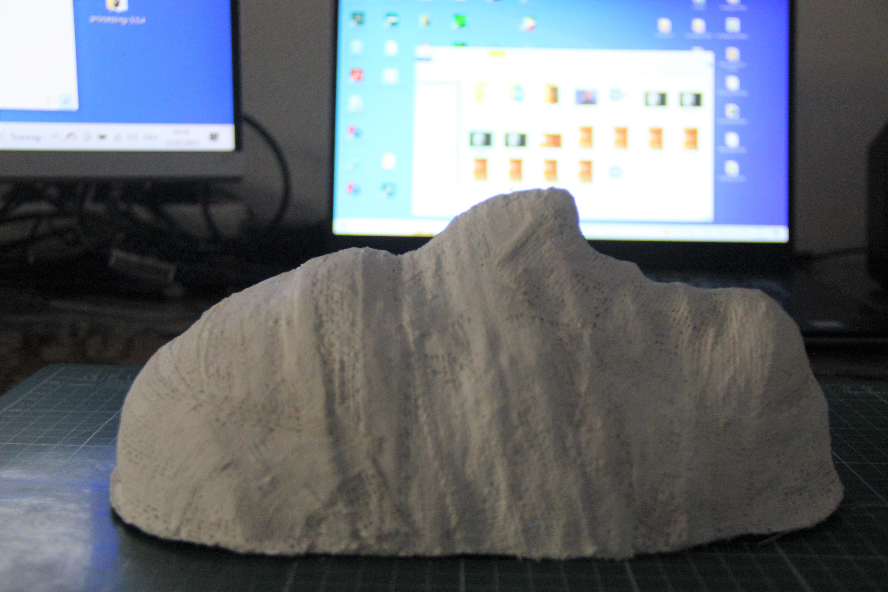
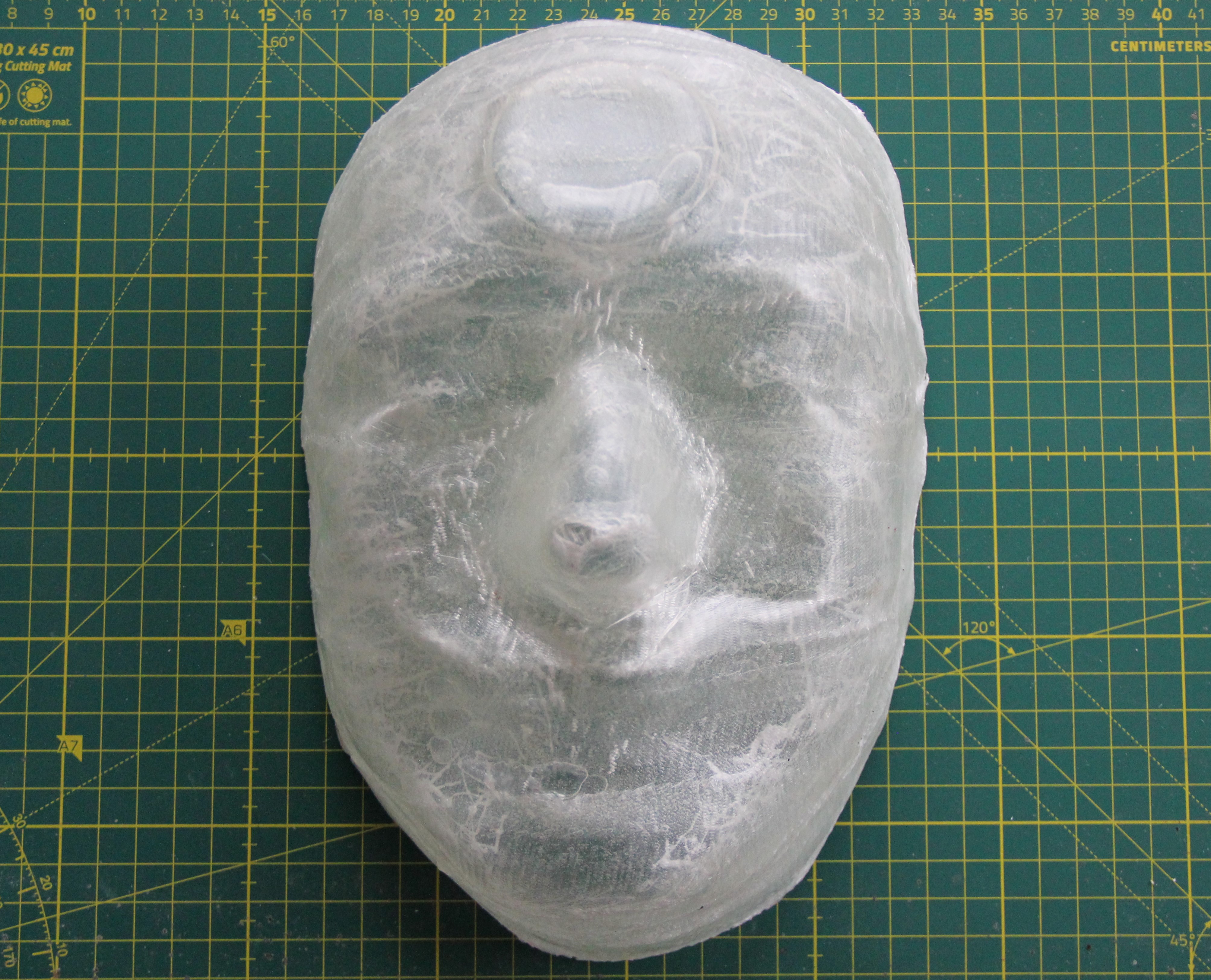
The first thing I did was to make a plaster cast of my face because the mask has to fit very well. After drying, the inside of the cast was smoothed with Moltofill.
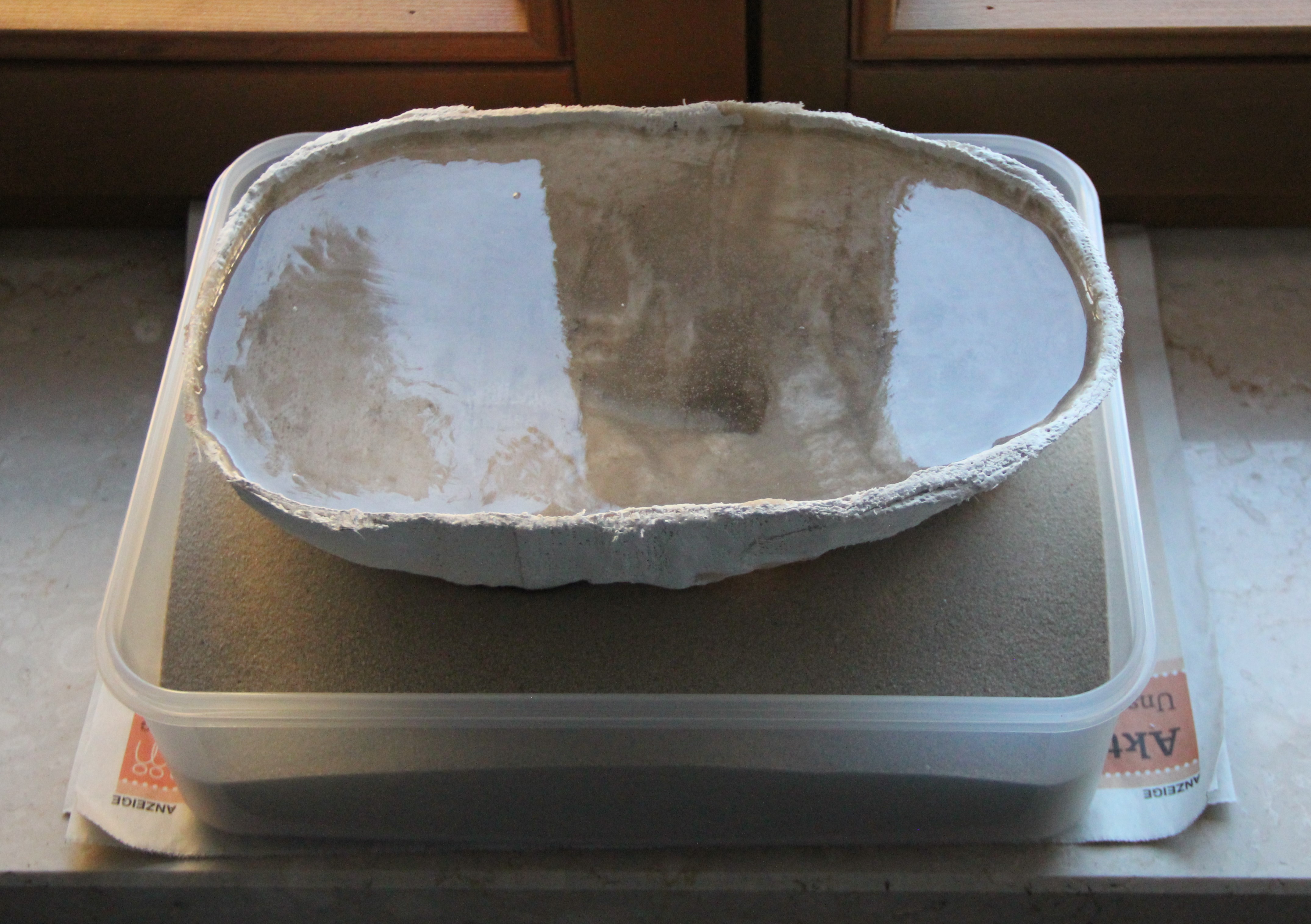
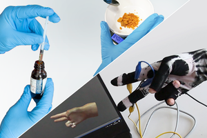
After multiple treatments with a release agent, the plaster mask was filled with epoxy-casting resin. The maximum filling height must be taken into account for the casting resin. The epoxy resin should cure very slowly. I chose one that takes at least 72 hours with a 2:1 ratio of resin to hardener. The sand bed serves to fix and dissipate heat.
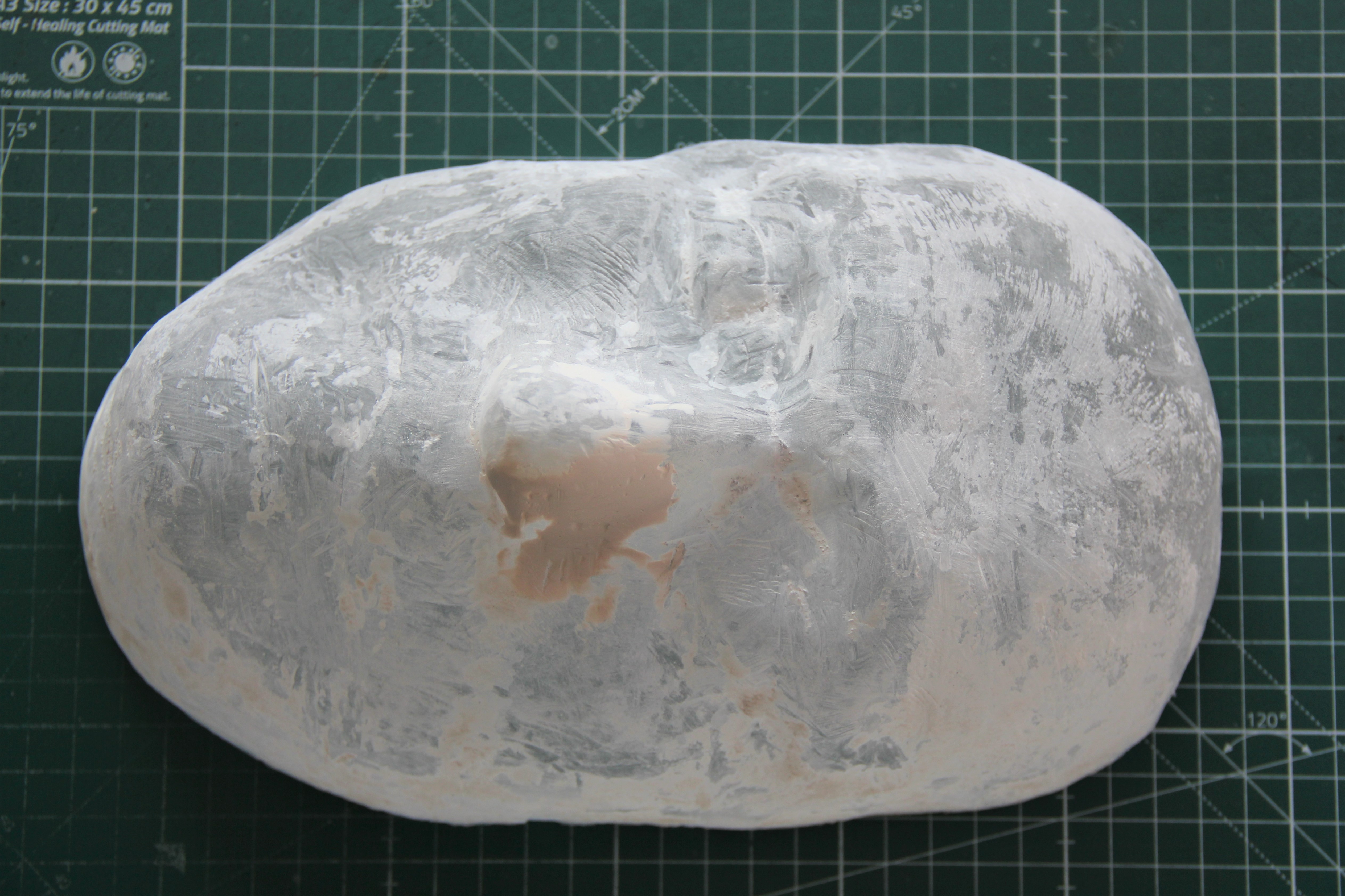
The demolding was more difficult than expected. Despite the release agent, the plaster mold could not be removed. The plaster was then removed mechanically with a wire brush and a Dremel. Incidentally, cured plaster is hardly soluble in water. The solubility in water under normal conditions is only 2.1 g/l.
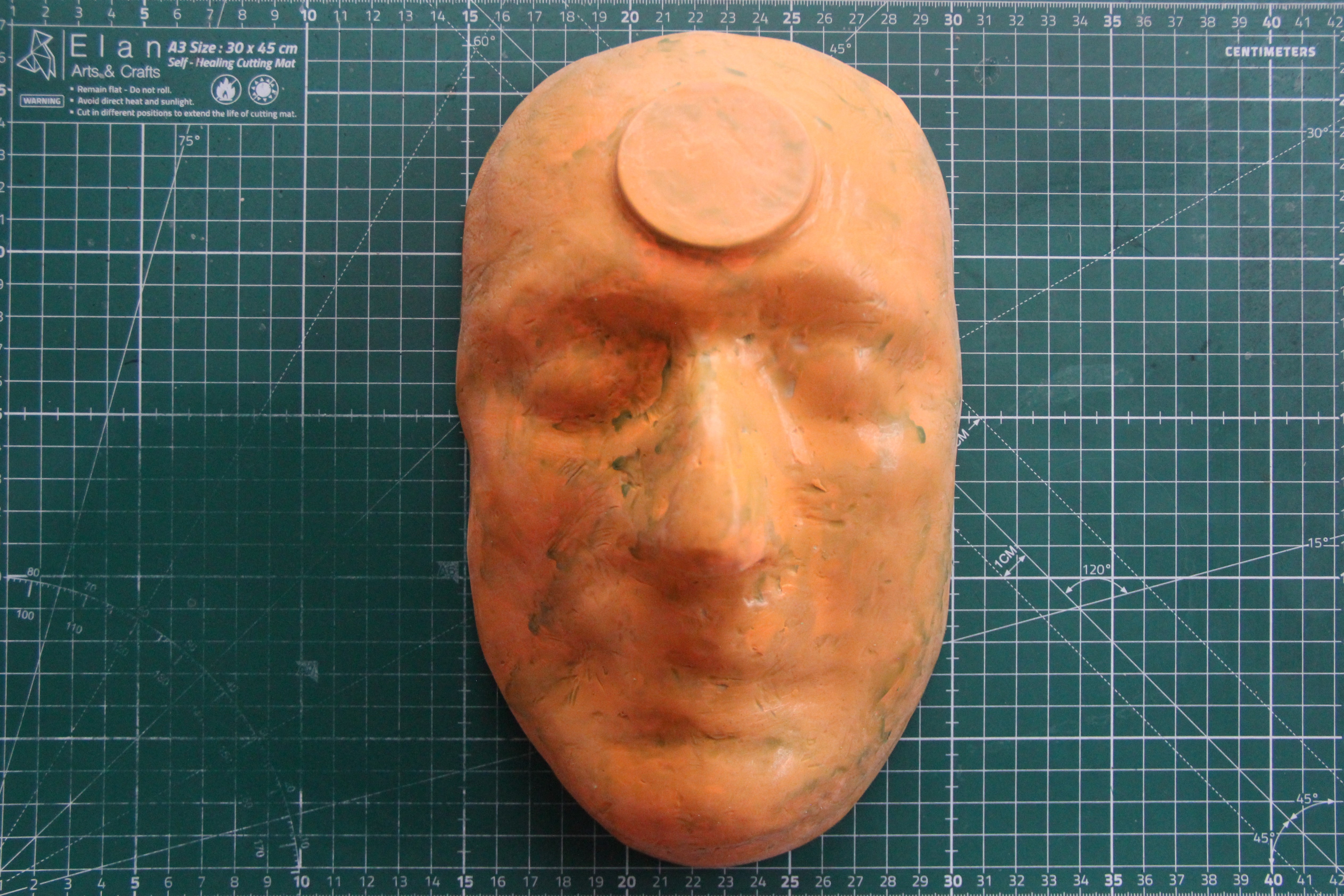
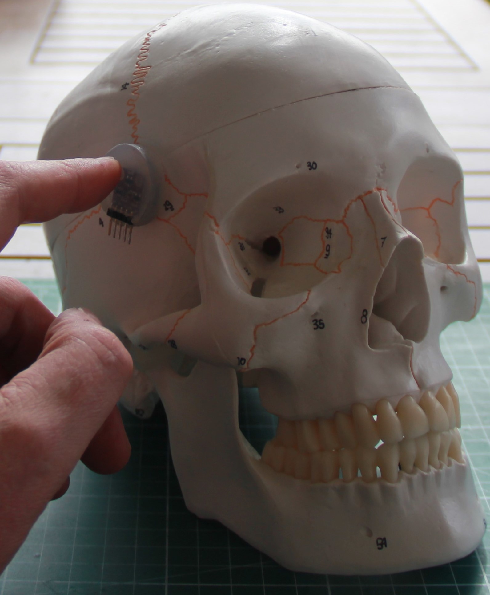
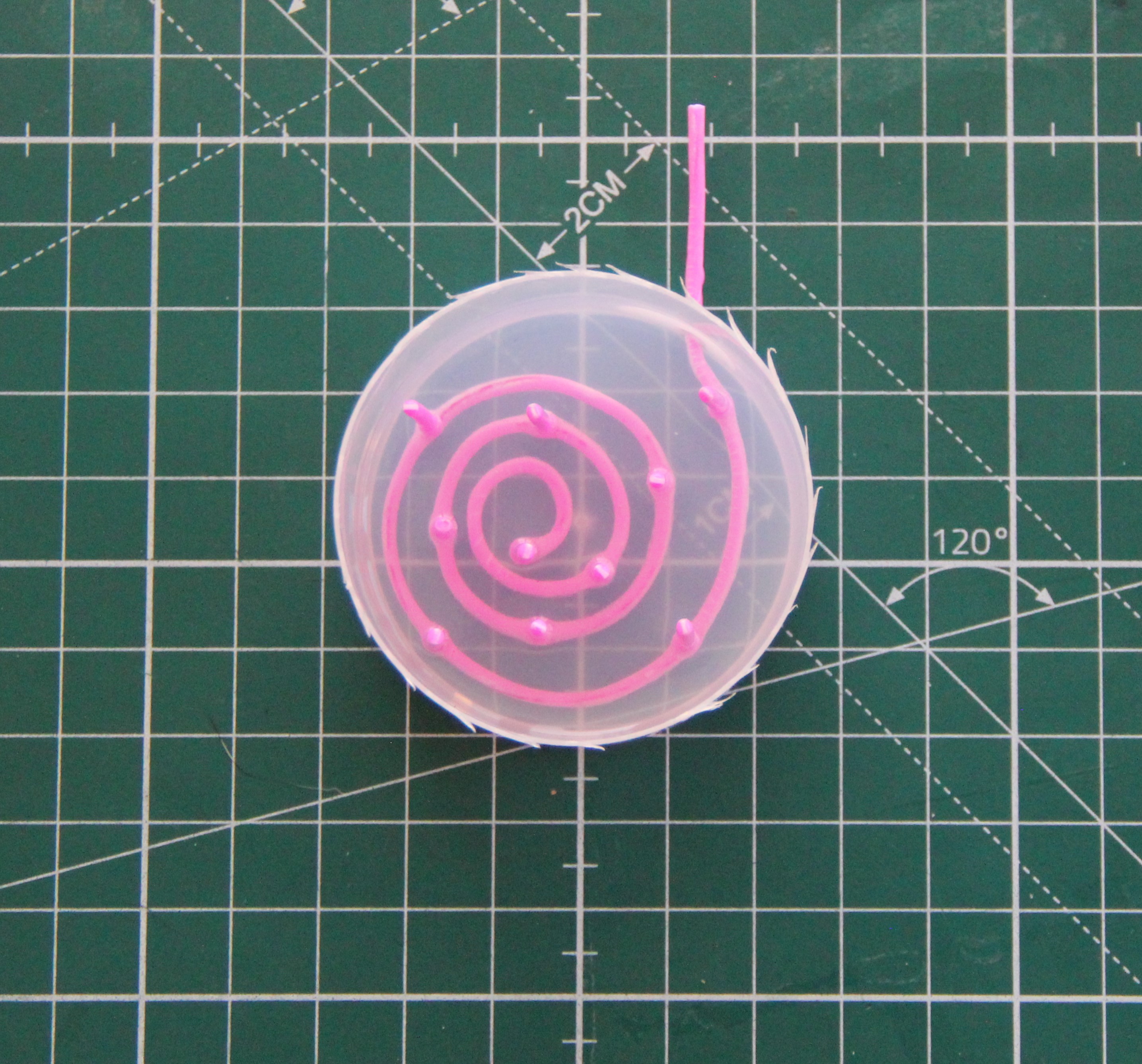
After the epoxy mold was filled, sanded, and painted with high-gloss resin spray paint, I applied release wax and then RESINPAL PVA release lacquer with a brush. The elevation on the forehead is for the microfluid pad.
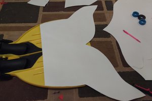
The mask was then molded using the lamination process. I used two layers of woven 200g/m2 fiberglass mat. This was cut into 3cm wide strips. A paper cutter is best suited for this. The mask is very sturdy and weighs only 100g.
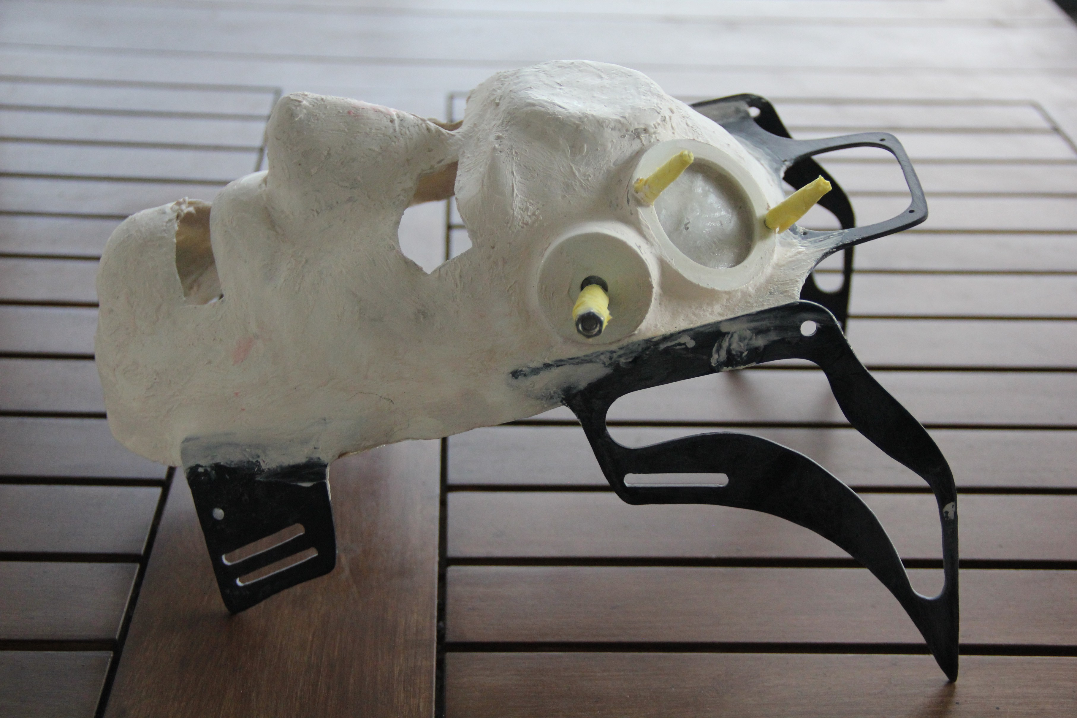
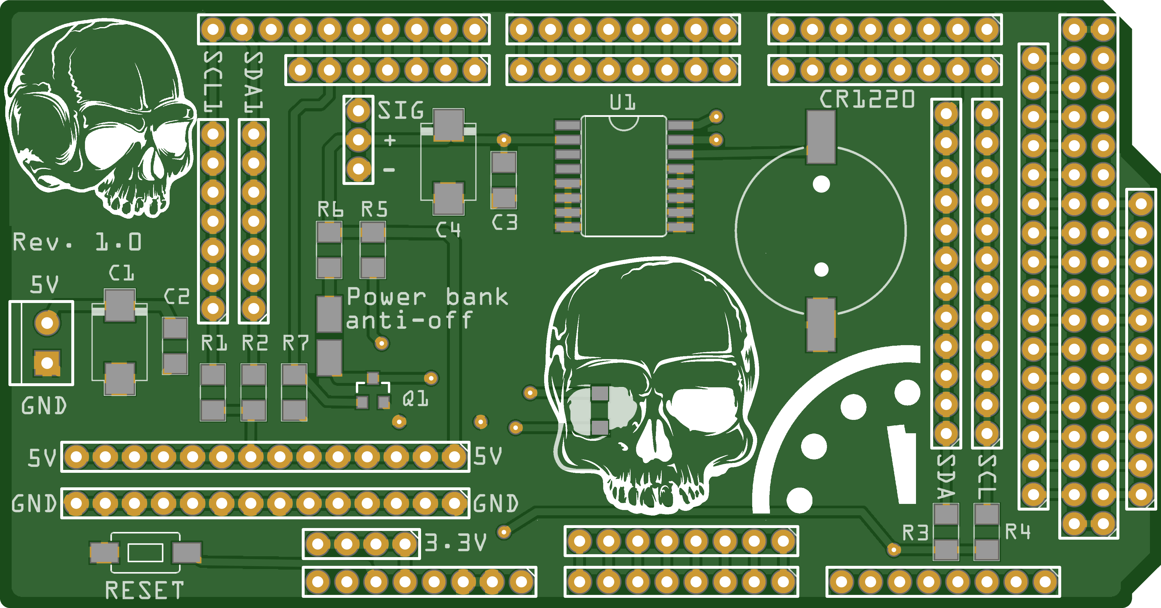
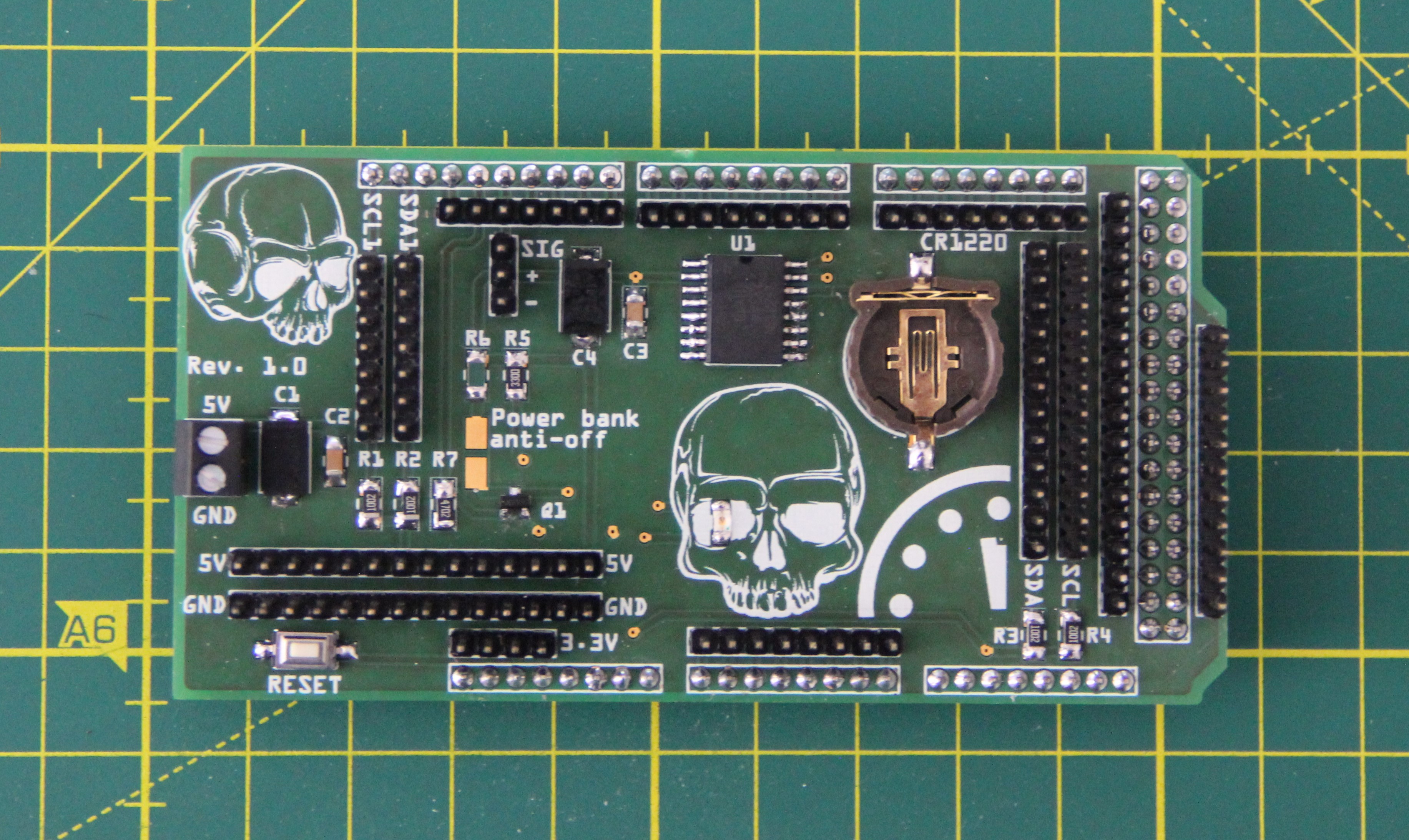
Then the attachments were designed in Inkscape, transferred to a 2 mm thick GRP sheet, sawed out, and attached to the mask with 2-component epoxy glue. They are used to attach the circuit boards, speaker, headband, and other peripherals. The cutouts for the mouth and eyes were also sawn out using templates. After curing, the mask was sanded and roughly filled. I used 2-component polyester putty for this. The best way to apply the putty is with your fingers, of course, protected by a nitrile glove. If you moisten your fingers with isopropanol, you can smooth the filler very well.
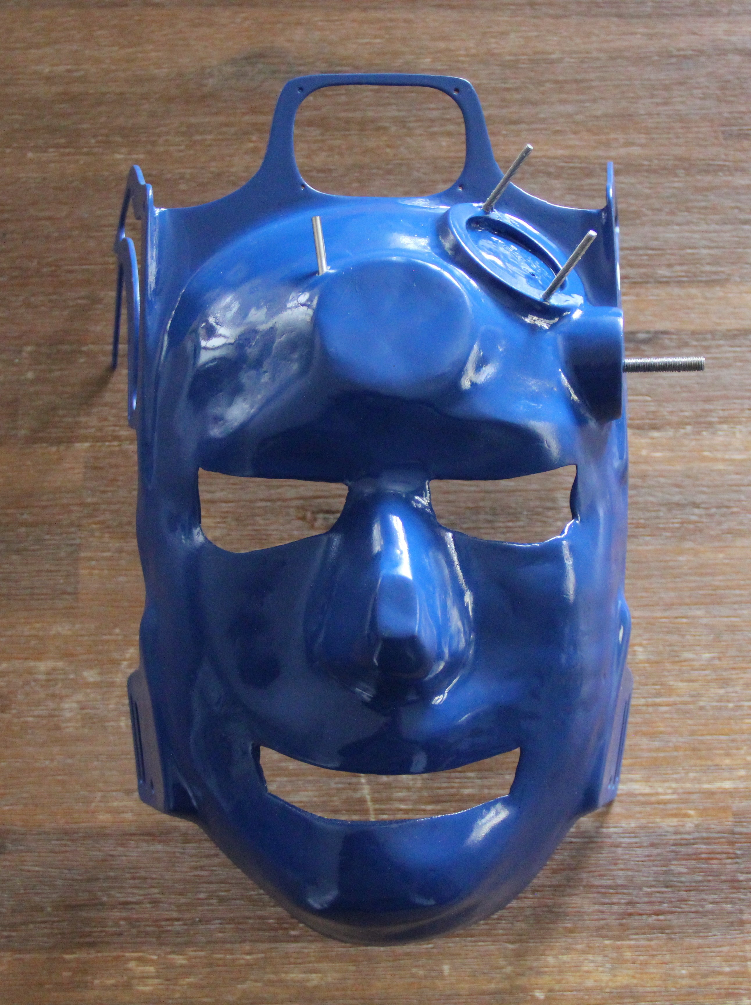
After more sanding, filling, and treatment with spray filler, the mask is ready for painting. I chose gentian blue (RAL5010) as the color for the mask, the attachments will be gold.
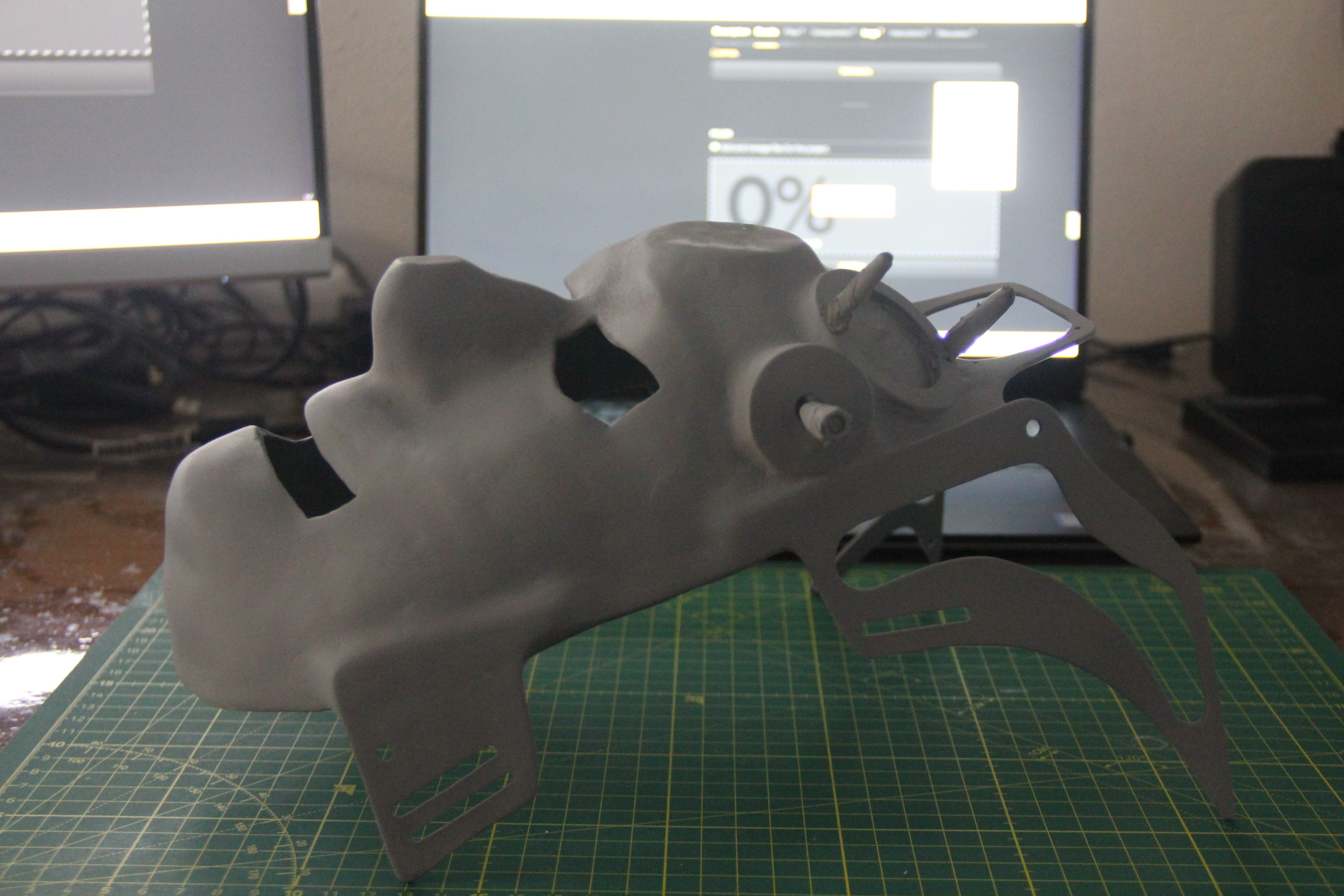
The weight of the mask has now increased to 300g. According to calculations, the finished mask will weigh about 450g, slightly less than the Oculus Quest 2 VR headset, except that the weight is better distributed in my mask.
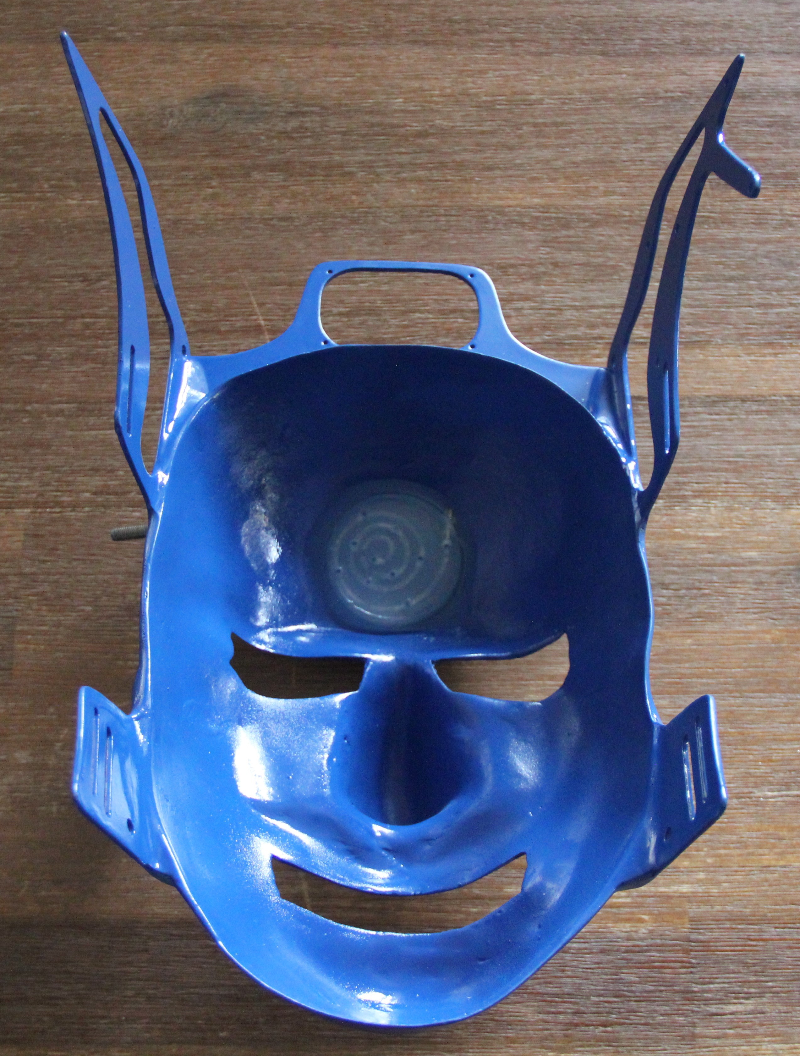
The front side of the mask after painting:
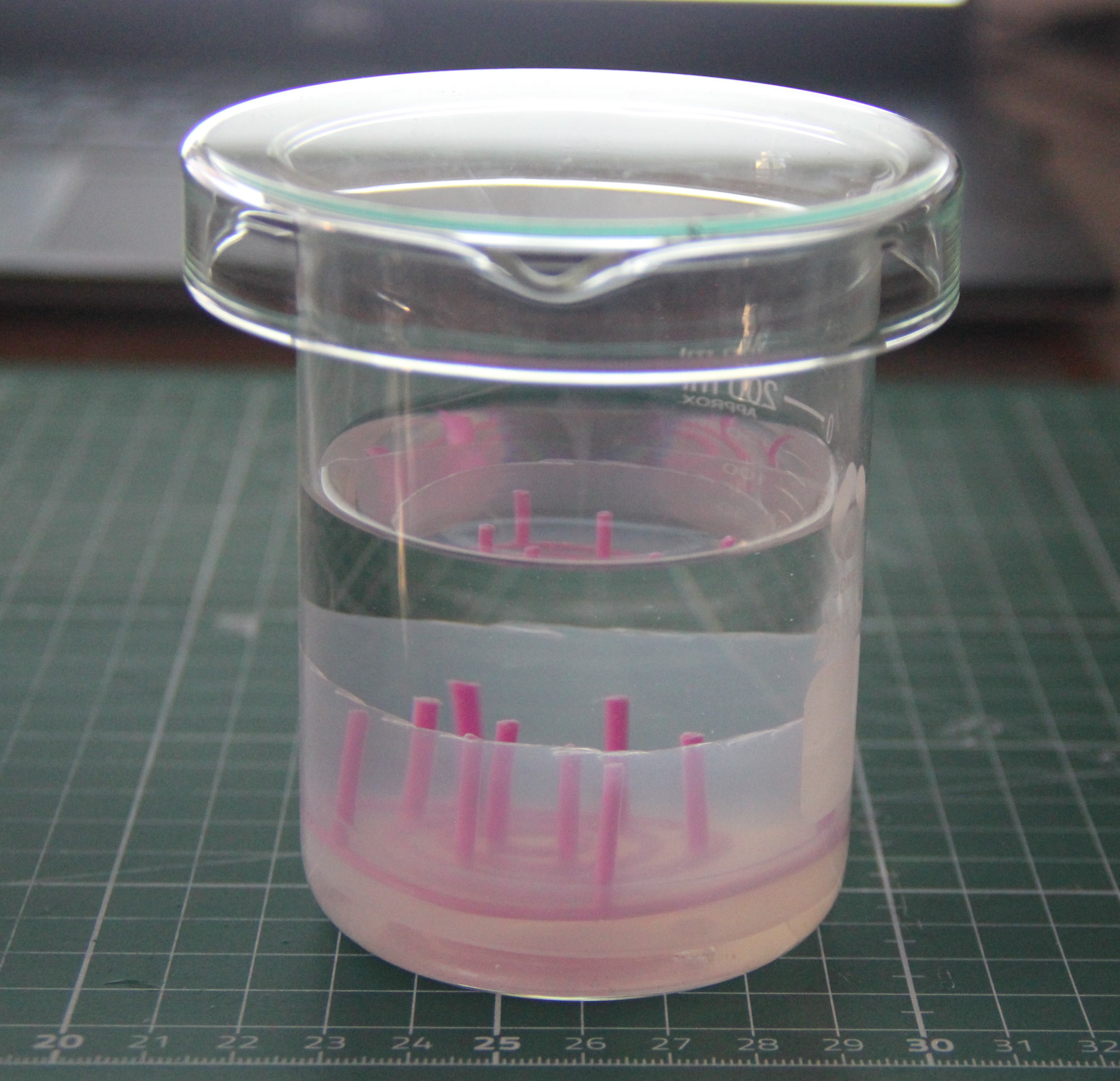
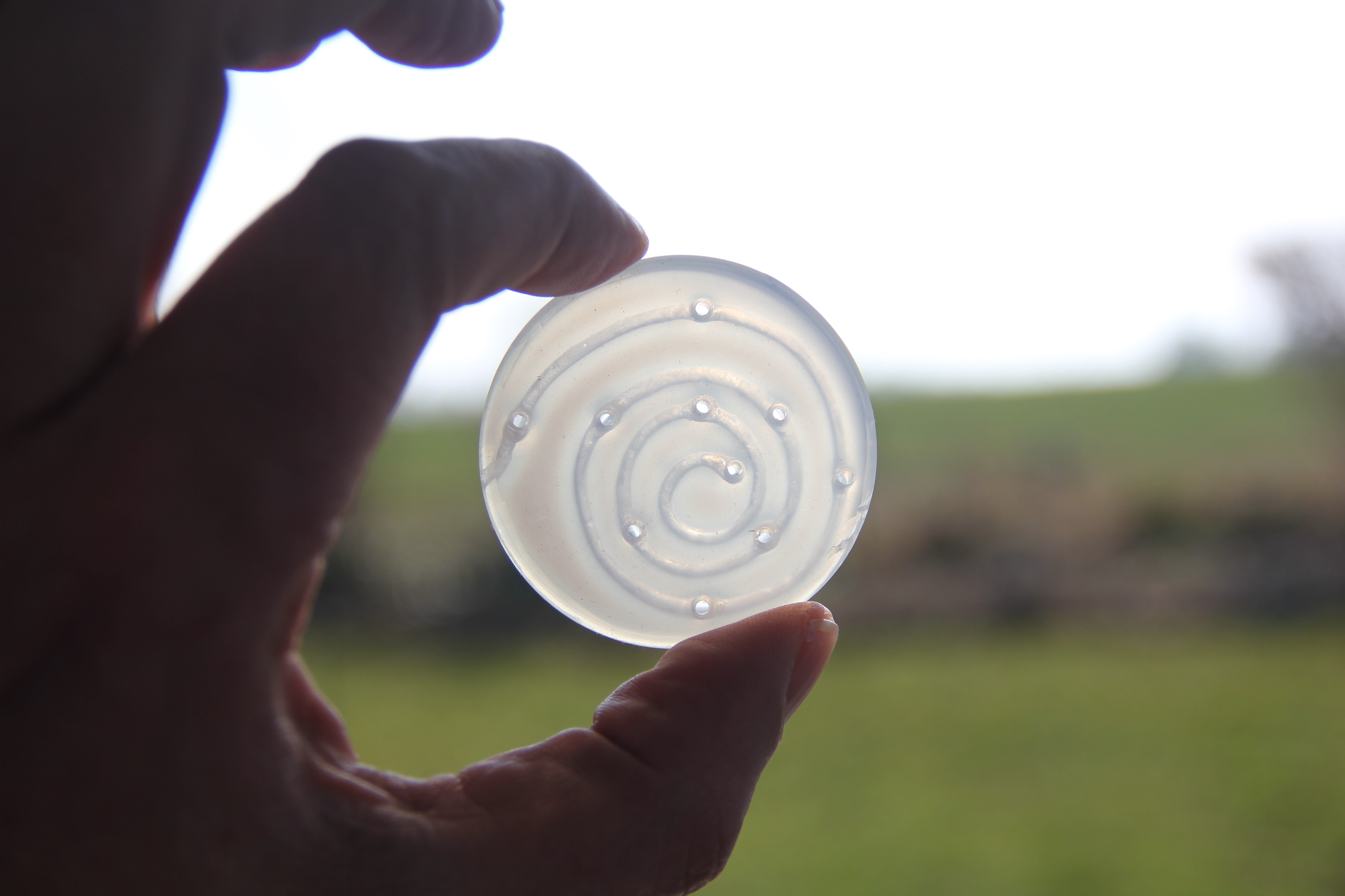
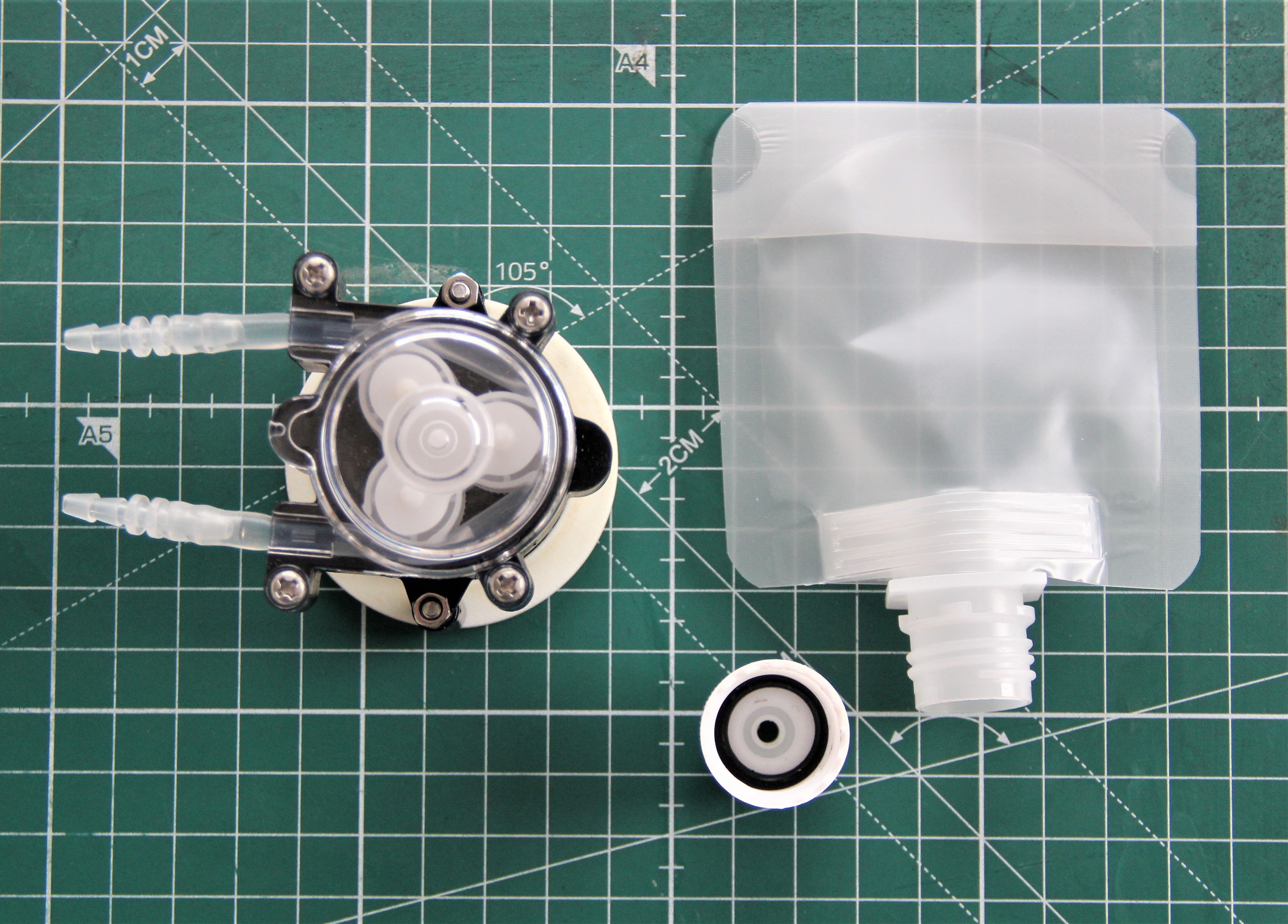
Back side with glued-in microfluid pad. I used 2-component silicone for this, which was previously degassed in the vacuum chamber.
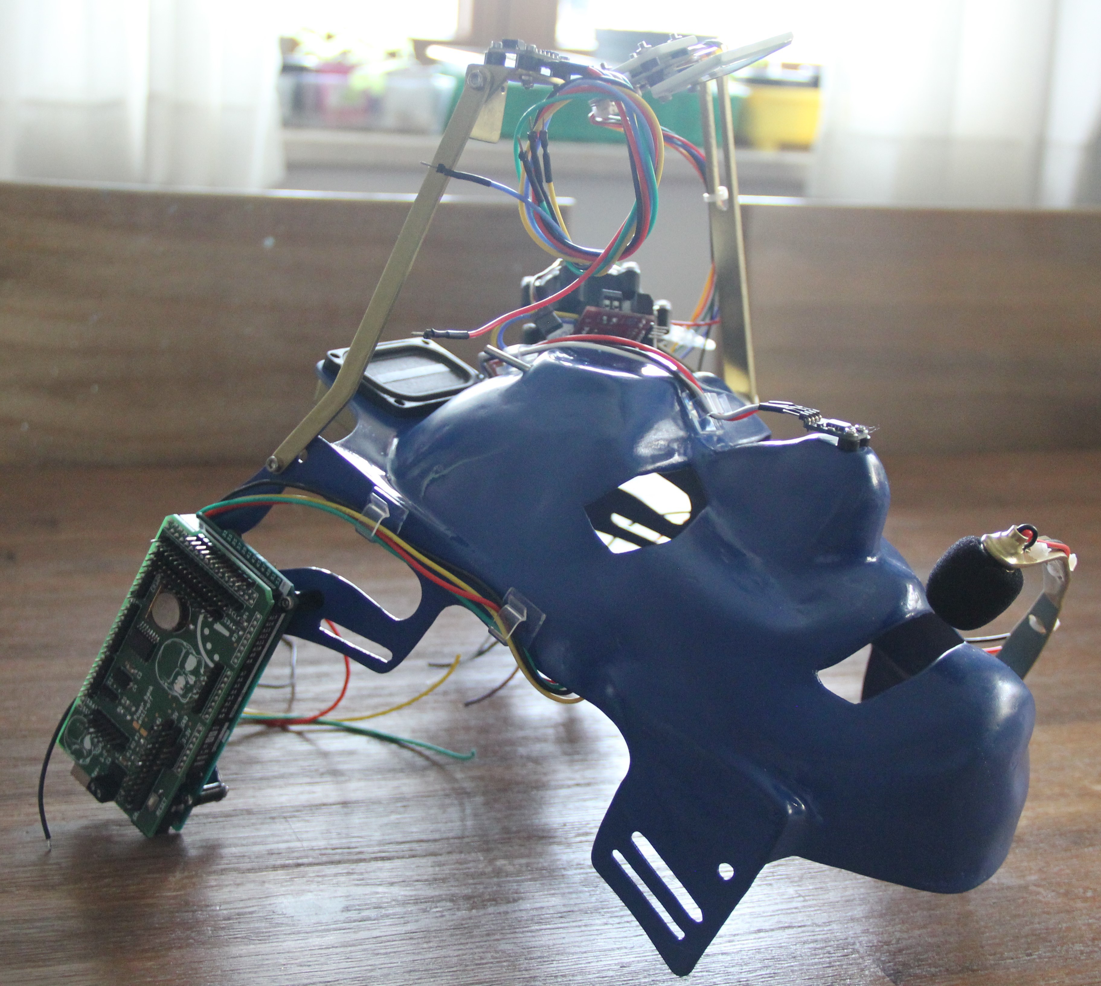
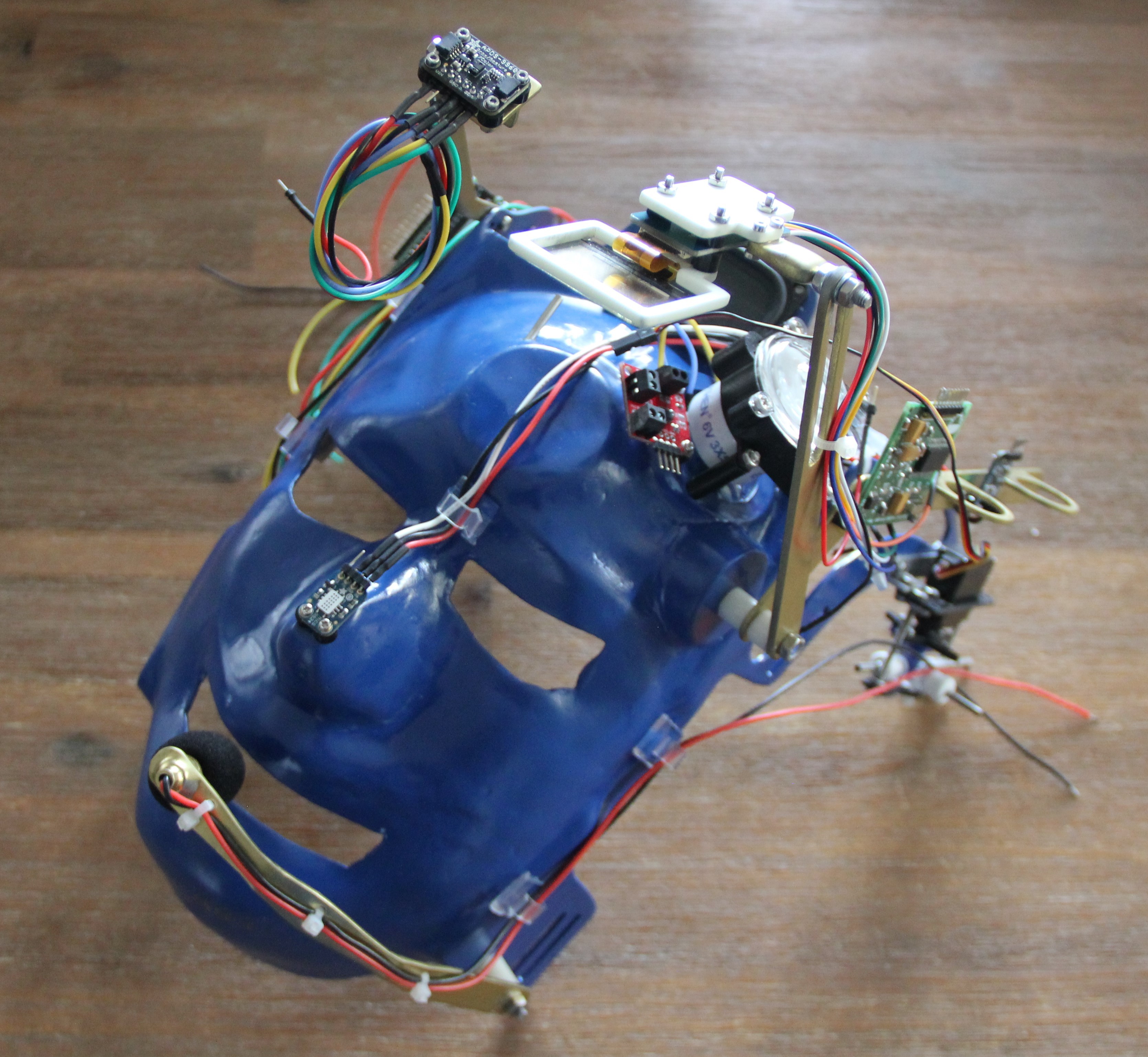
Partly assembled mask:

This work is licensed under a Creative Commons Attribution-NonCommercial 4.0 International License.
 Quinn
Quinn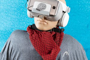
 Varun Suresh
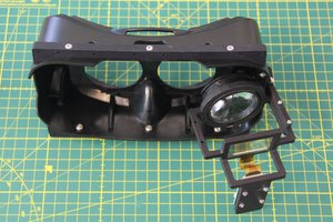
 Drix
Drix