Ruslan
Operating time on 1 battery charge - 8 hours 40 minutes.
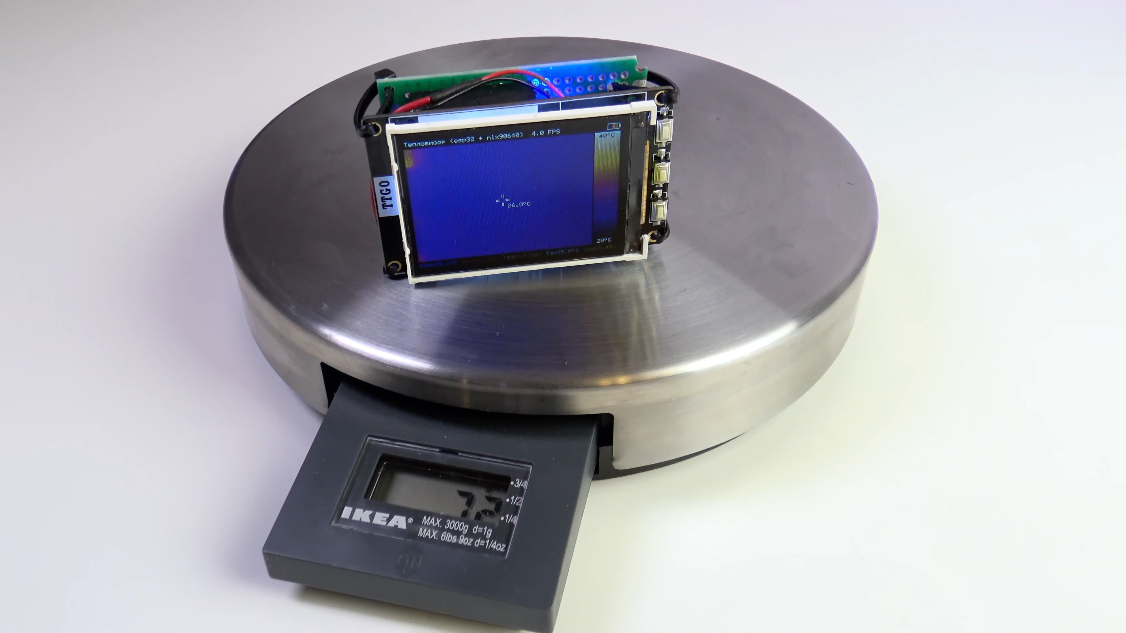
Thermal imager weight (without case) - 72 grams
Let's take a closer look at the details of the project…
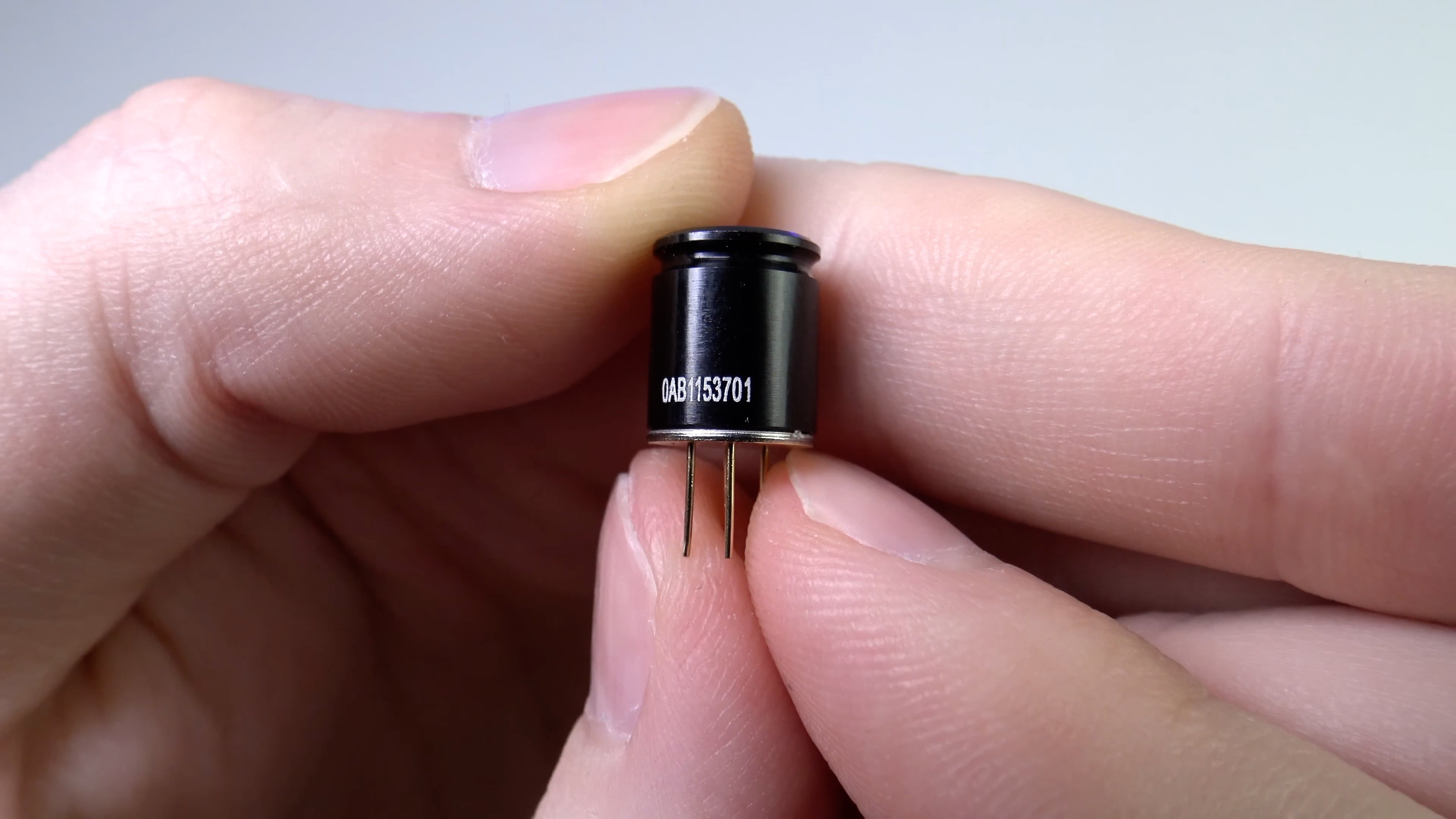
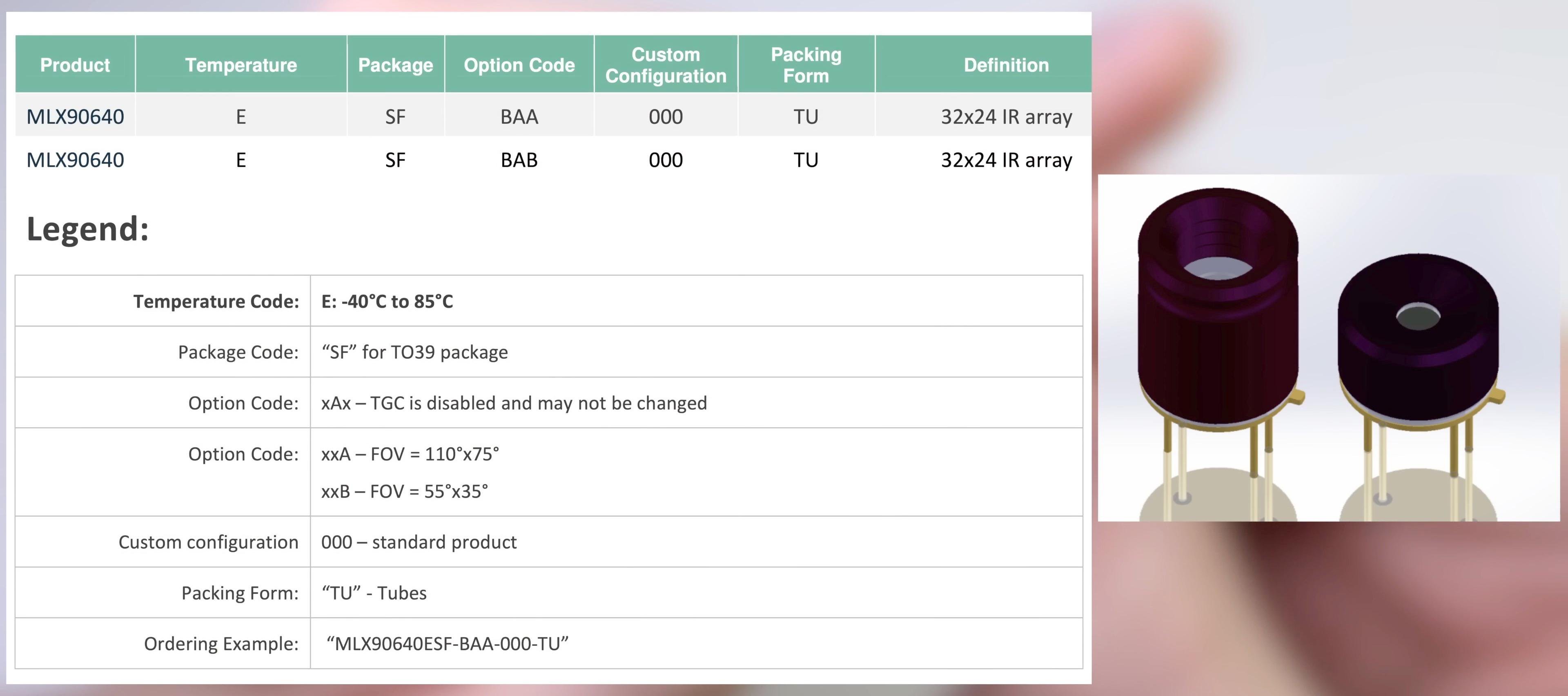
MLX90640 sensor
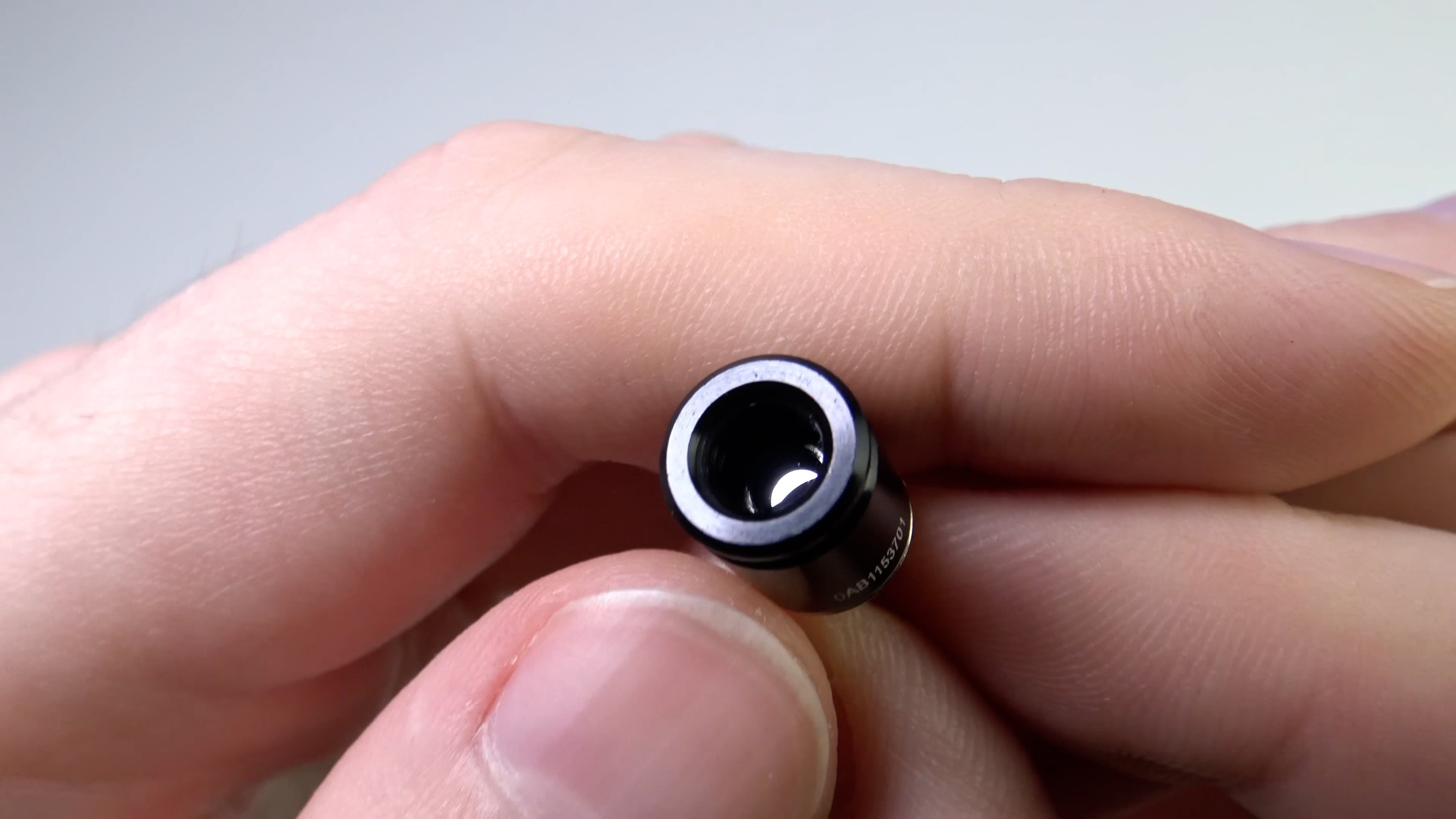
There are 2 versions of the sensor:
With the letter A in the name has FOV 110 / 75
With the letter B in the name it has FOV 55 / 35 - I have one
Inside the sensor is a 32x24 matrix of elements sensitive to IR radiation. The manufacturer allows up to 4 defective pixels. They are stored in EEPROM and are considered to be interpolation from neighboring pixels.
Inside the sensor there are 768 IR receivers (!!!) + VDD meter + built-in chip thermometer (it estimates the temperature of the sensor case).
The sensor is factory calibrated. Calibration coefficients are stored internally in the sensor in EEPROM.
Temperature range: -40…+300
Operating temperature range: -40 ... +85
The sensor is powered by 3.3 V (up to 3.6 V). Withstands 5V supply for a short time.
Average current consumption 20 mA.
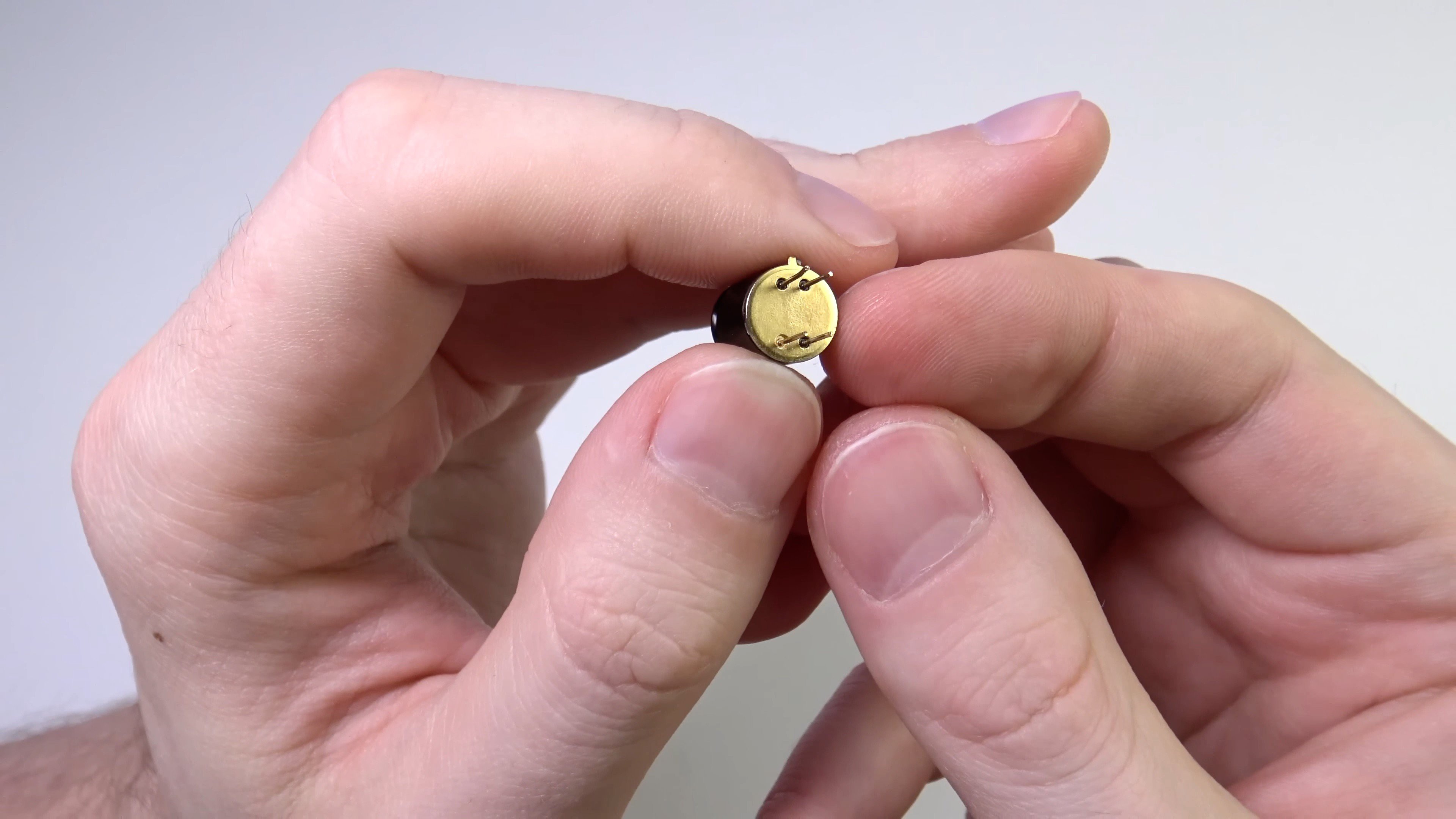
The sensor has 4 pins. 2 of them for power and 2 more for the i2c interface.
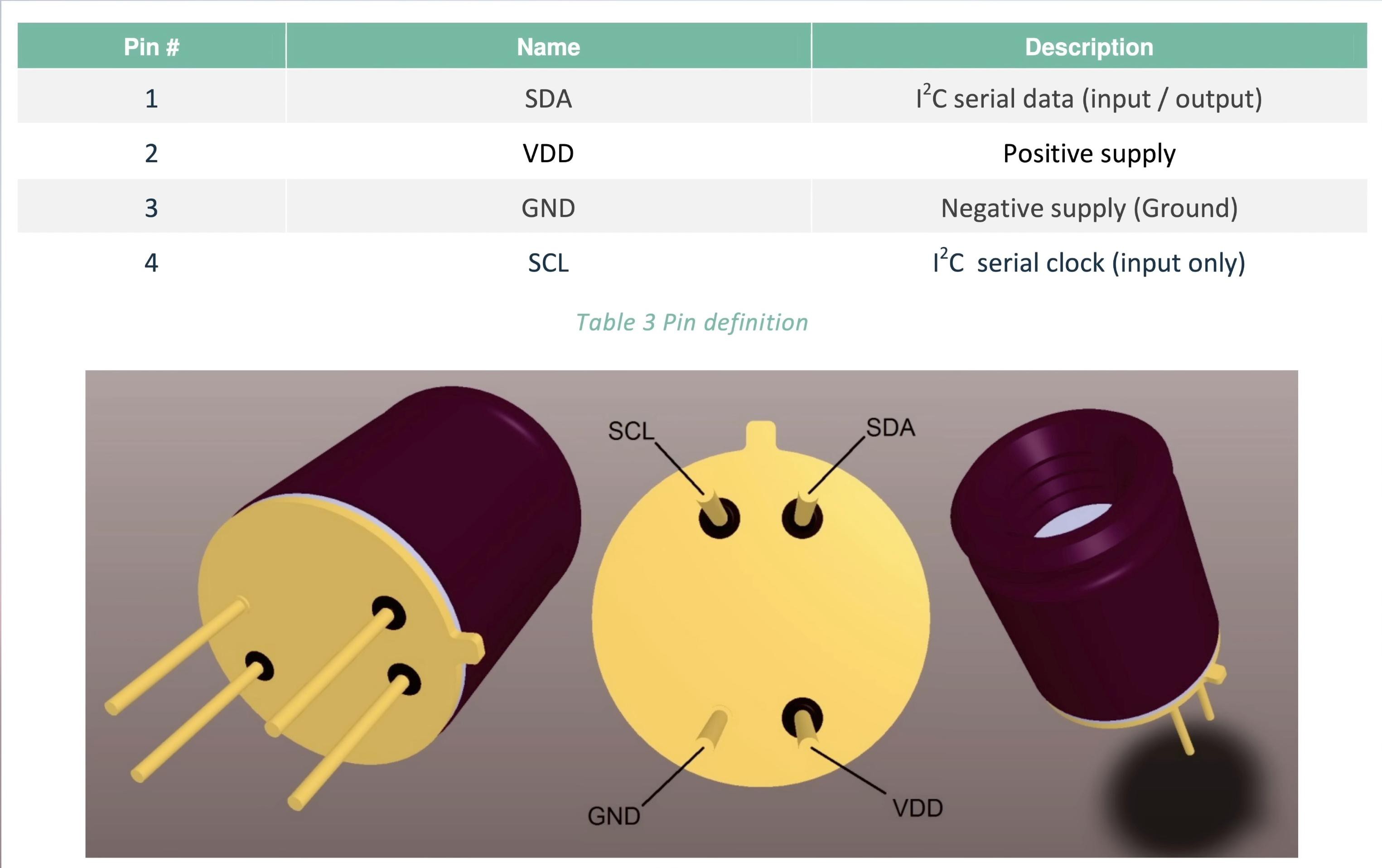
The i2c pins are 5V tolerant. The i2c frequency is up to 1MHz. The i2c address can be changed by software, the default is 0x33.
Software from Melexis
In addition to the sensor, I have an evaluation board from melexis (EVB90640-41).
The board allows you to connect the sensor to a computer.
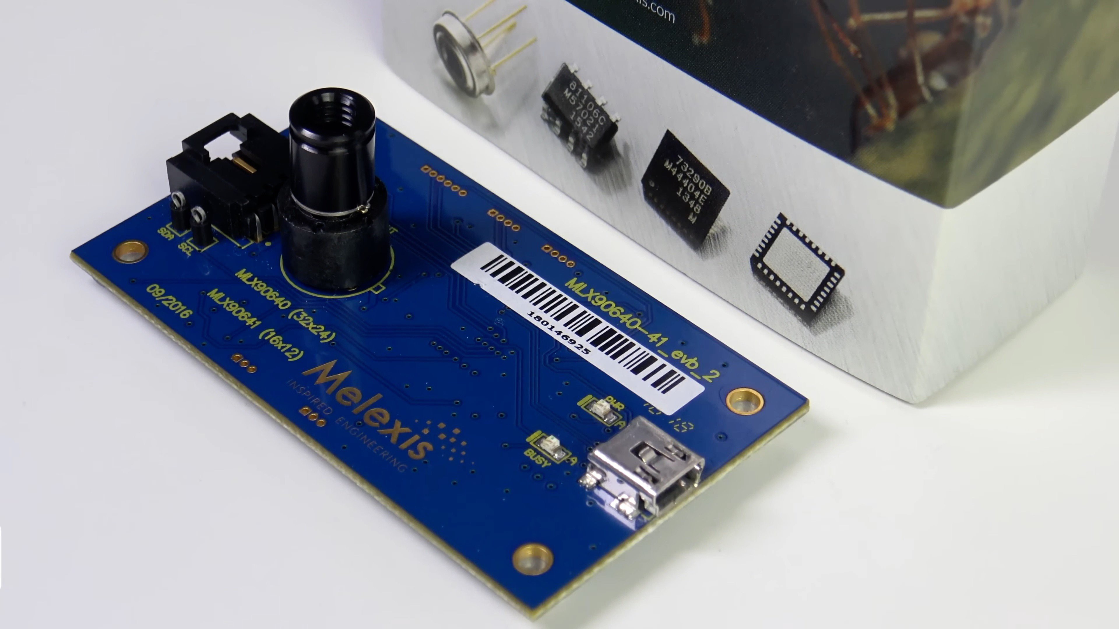
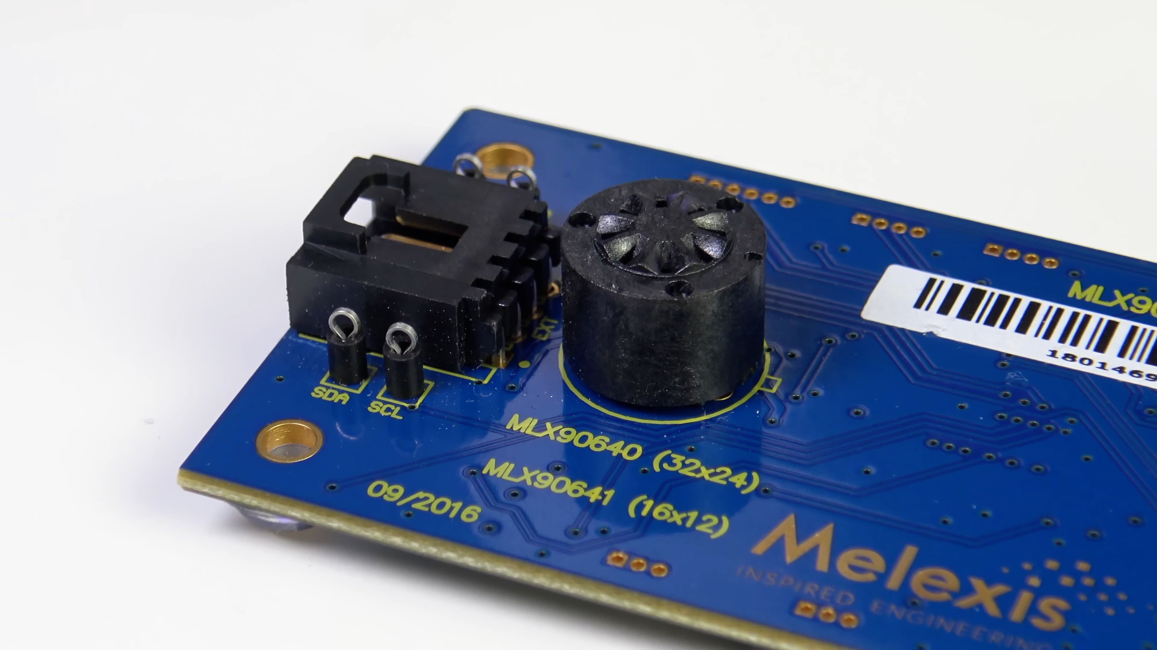
The board has a socket where you need to insert the sensor, and a mini-USB port for connecting to a computer.
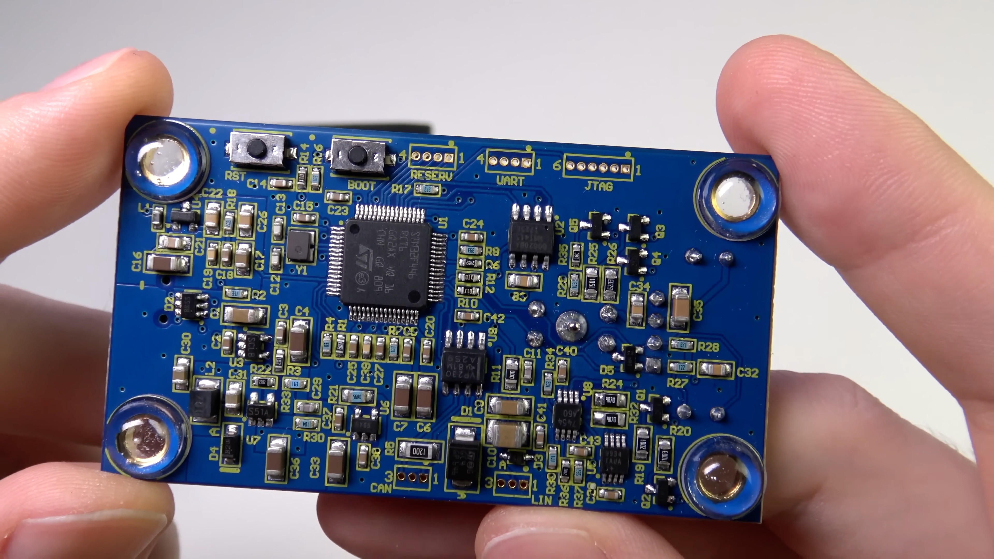
The evaluation board is based on the STM32F446 microcontroller.
The board has CAN and LIN interfaces. The purpose of these interfaces is unknown to me. Most likely Melexis implemented them for one of their customers.
VP230 - CAN transceiver
80020BA - LIN transceiver
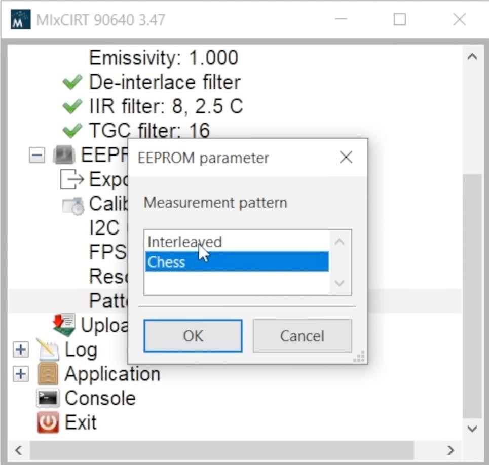
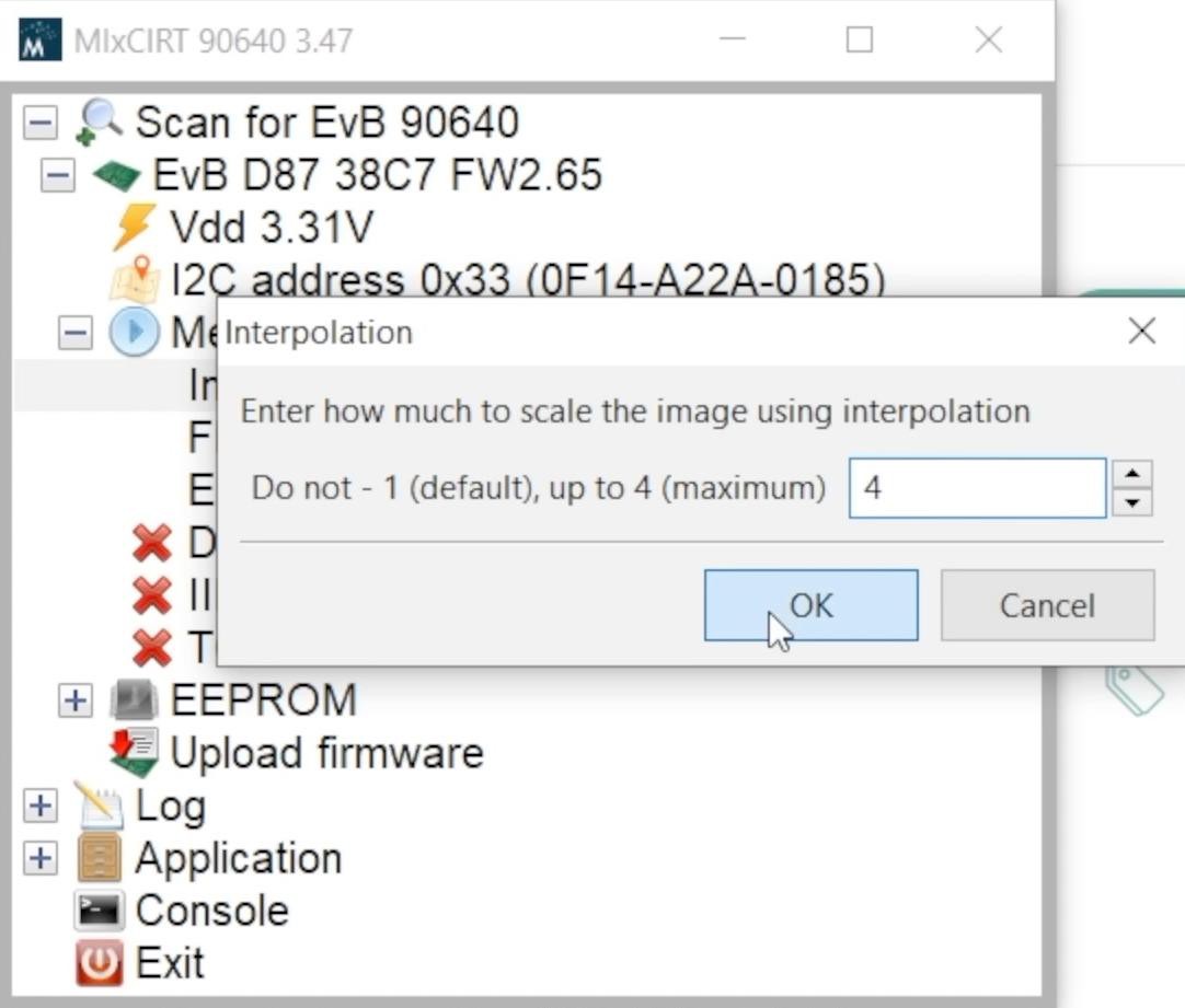
In MlxCIRT 90640 software, you can view general information about the sensor, start data acquisition and configure parameters in EEPROM.
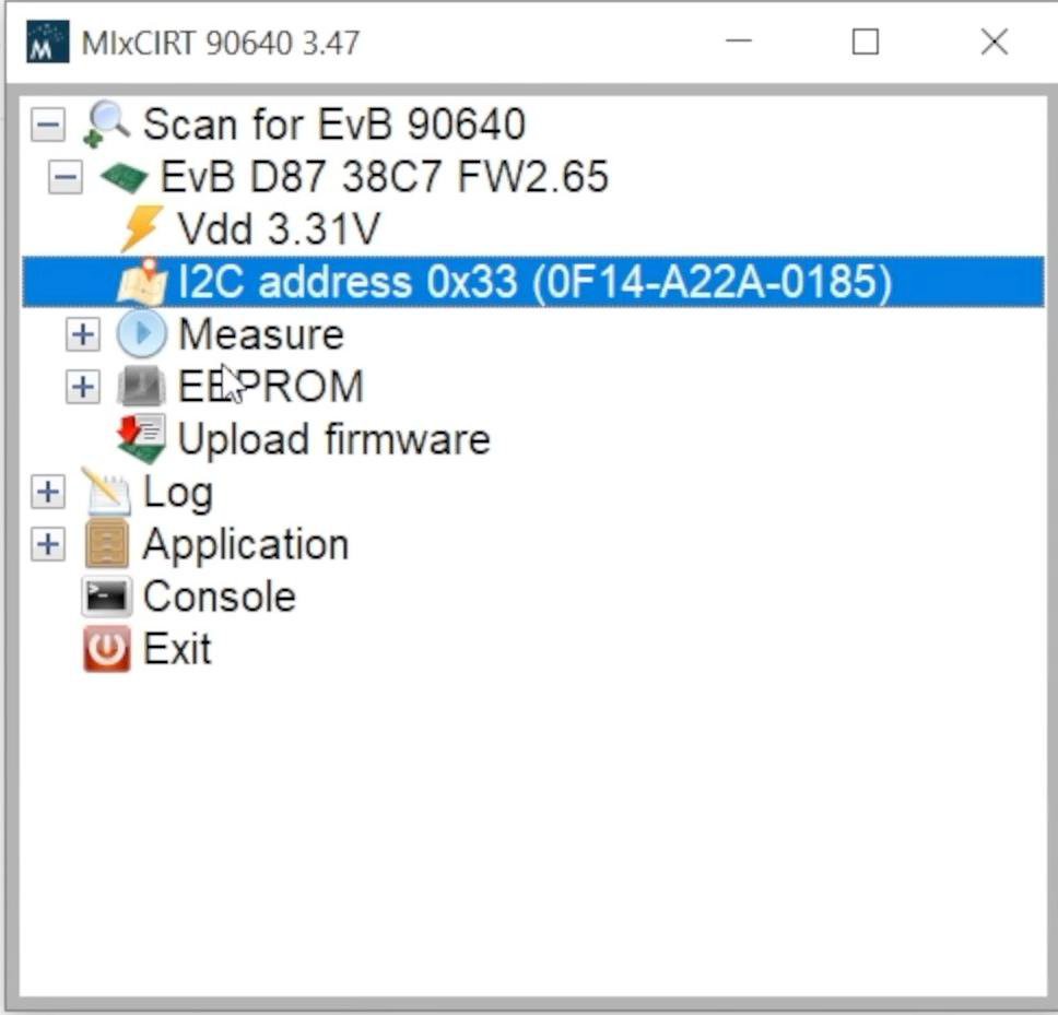
The frame rate is selectable from 0.5 Hz to 64 Hz.
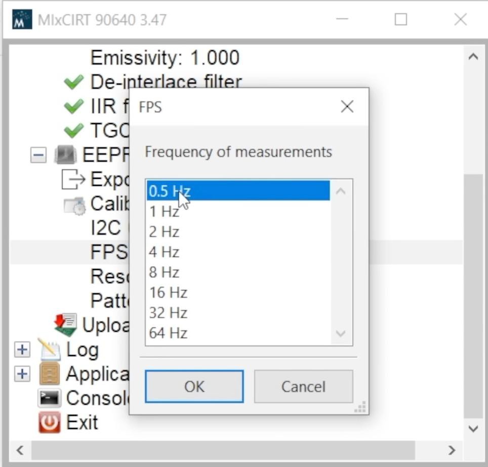
This is the frequency of reading half a frame from the matrix (the matrix is scanned in 2 stages using a checkerboard or interlaced pattern).
The matrix scan template can also be selected in MlxCIRT 90640. The manufacturer recommends the chess template because the factory calibration is done for it.
You can update the firmware of the demo board in MlxCIRT 90640.
Reading thermograms is possible in a CSV file for further analysis.
Let's start reading thermograms.
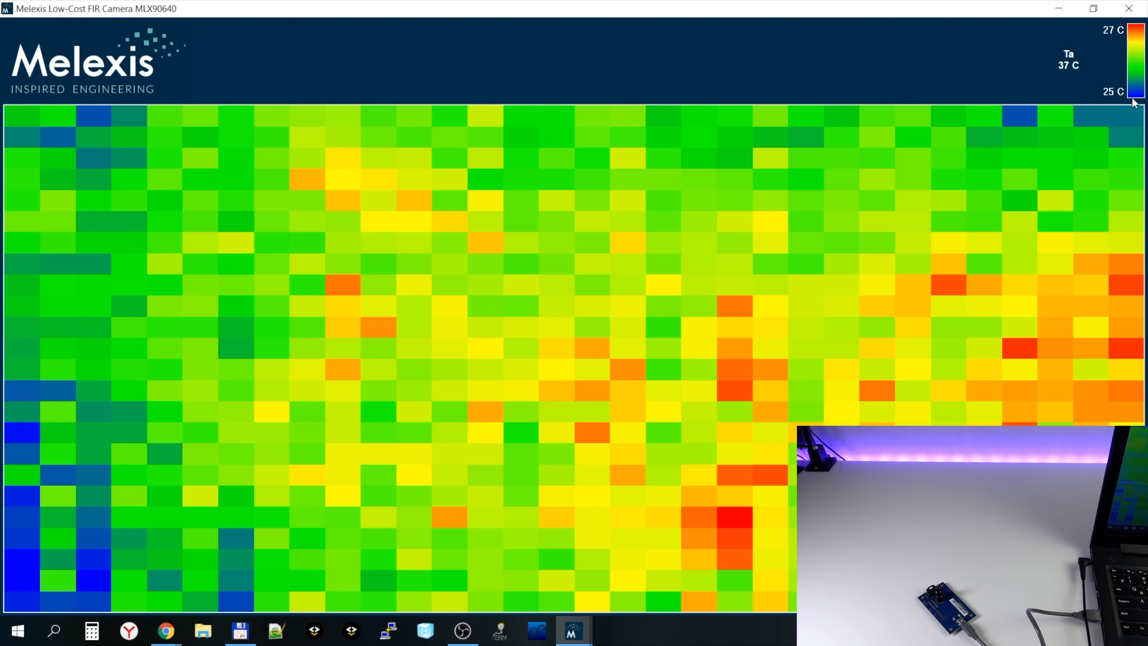
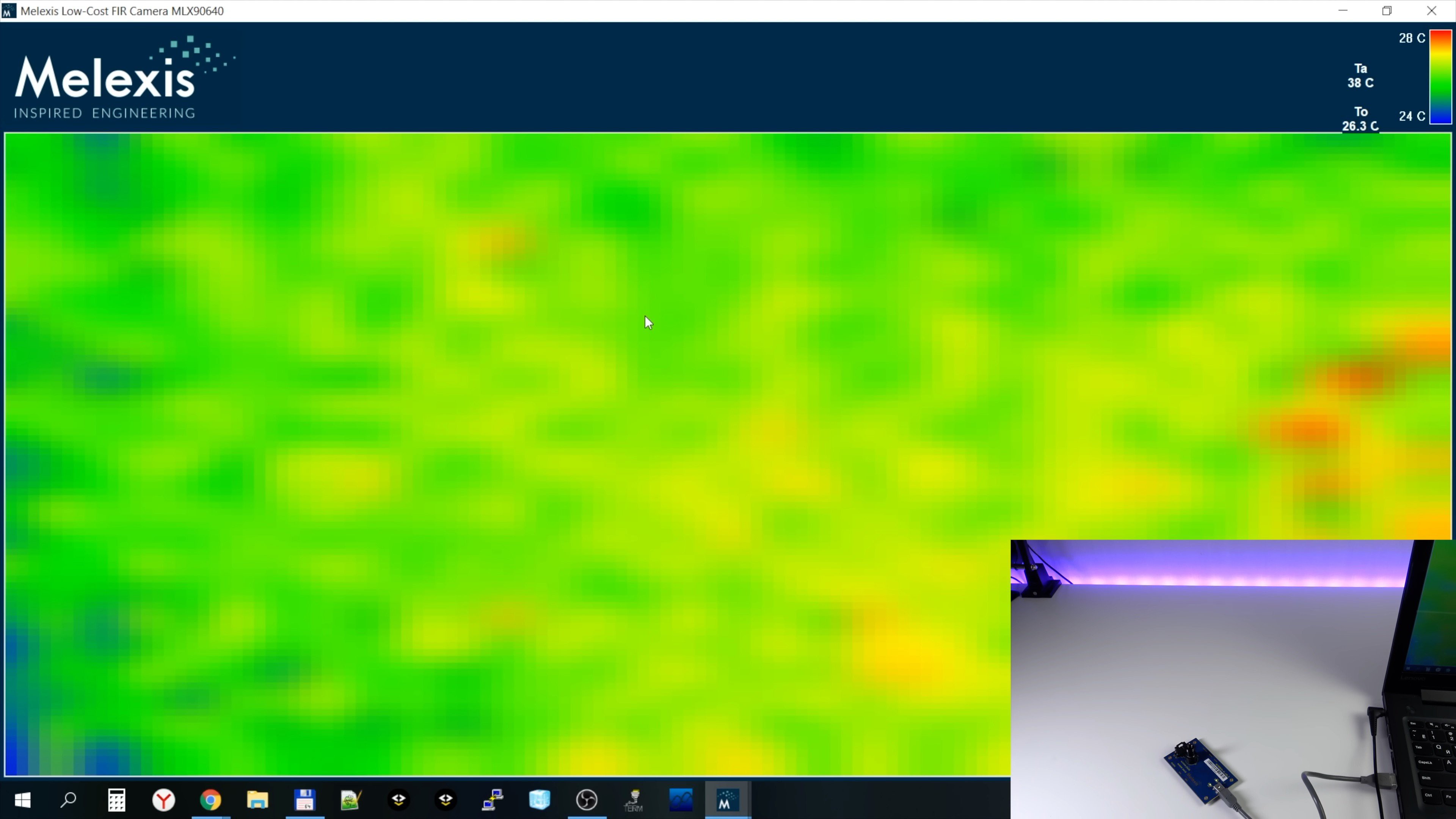
Now the sensor is directed to the ceiling. There are no hot and cold objects on it and you see a rather noisy image. This is because the software has automatically chosen a very narrow temperature range for the color scale - only 2 degrees.
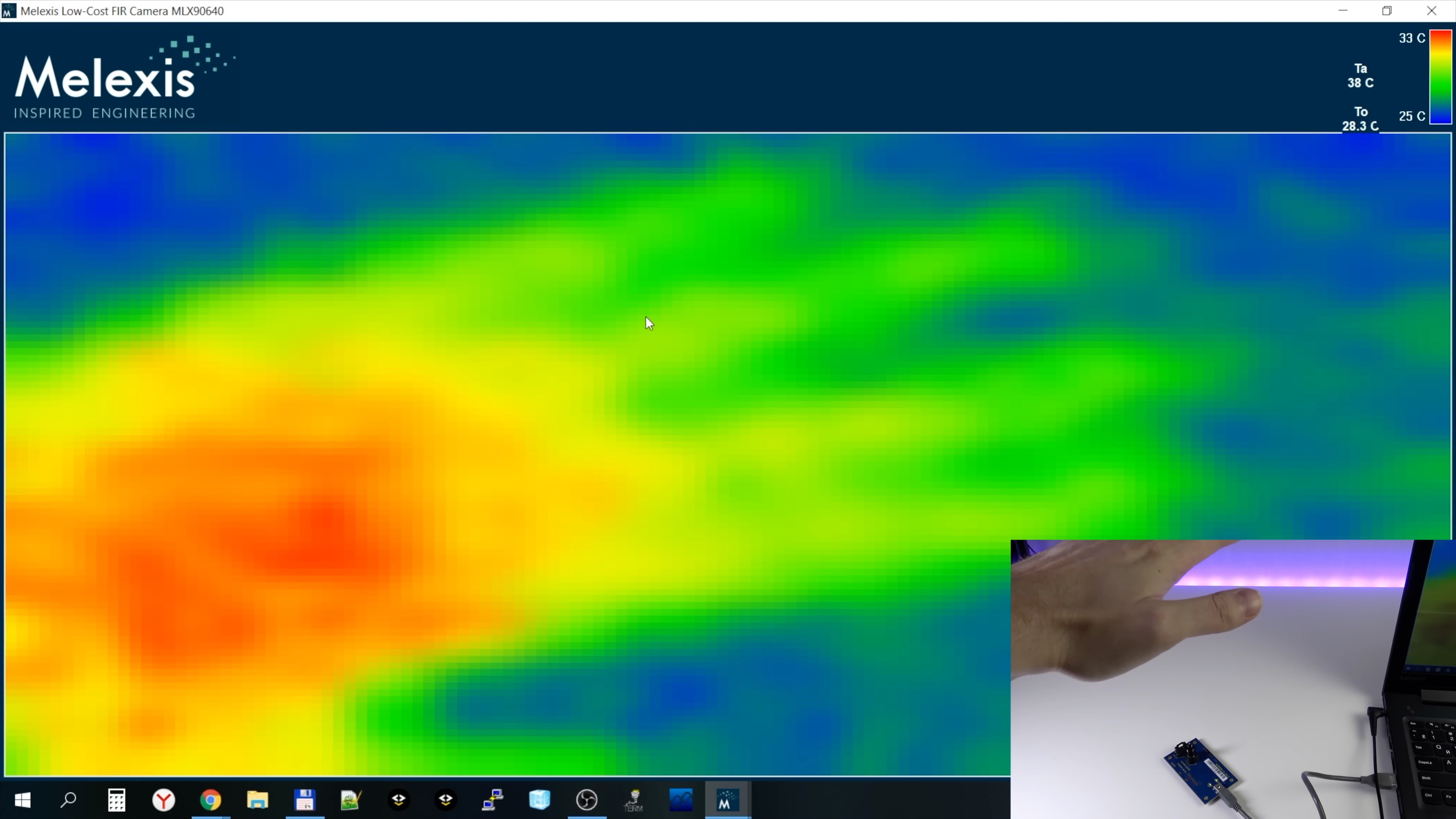
Now I brought my hand into the field of view of the sensor and this is what the thermogram looks like now:
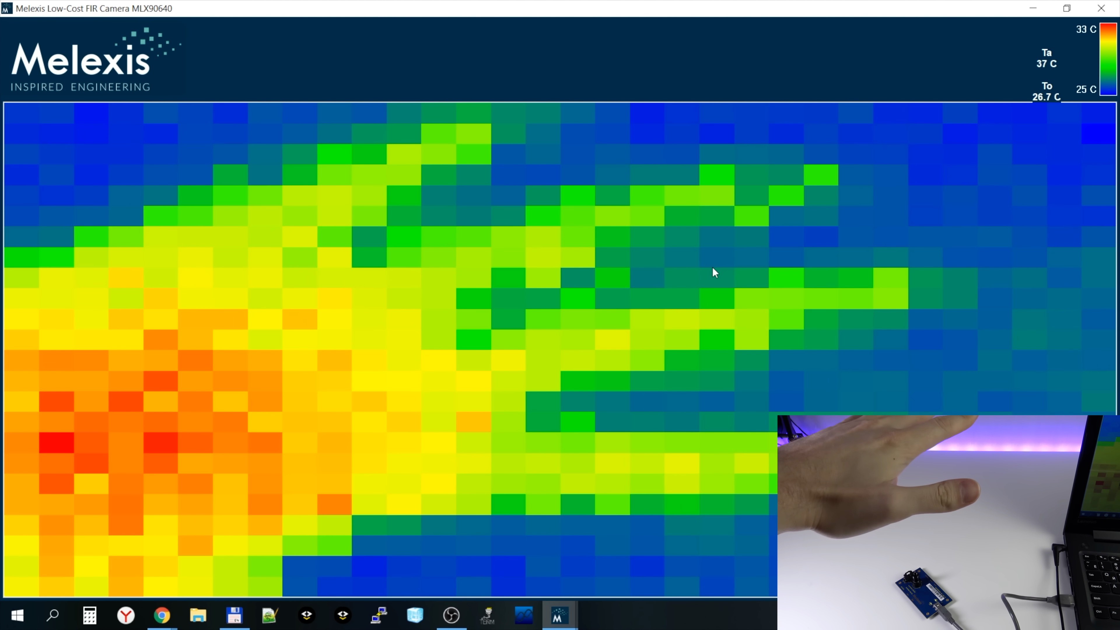
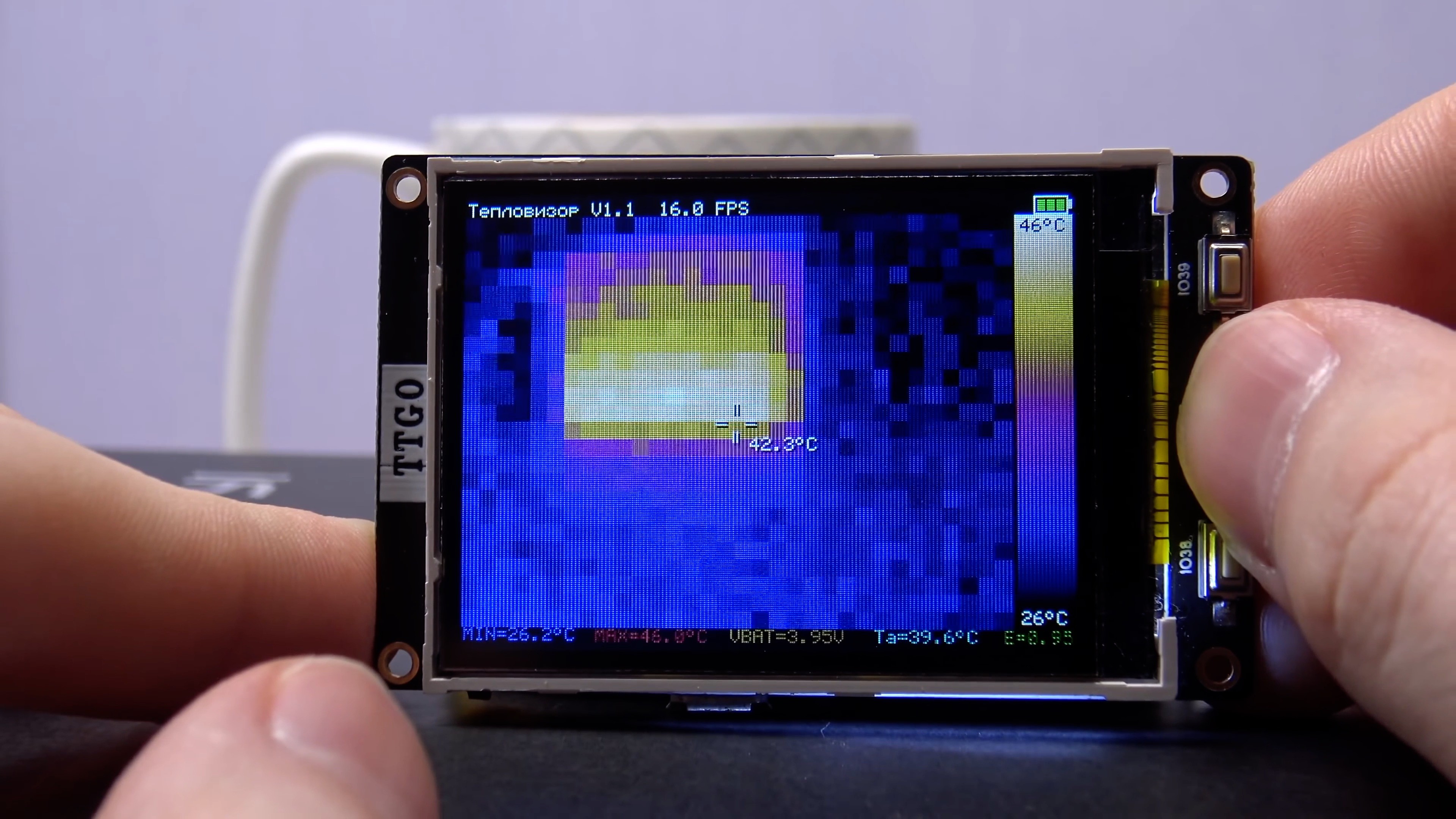
During a fast movement (FPS = 4 Hz is selected), we see a characteristic “checkerboard defect” on the thermogram, associated with the order of scanning the matrix by the sensor:
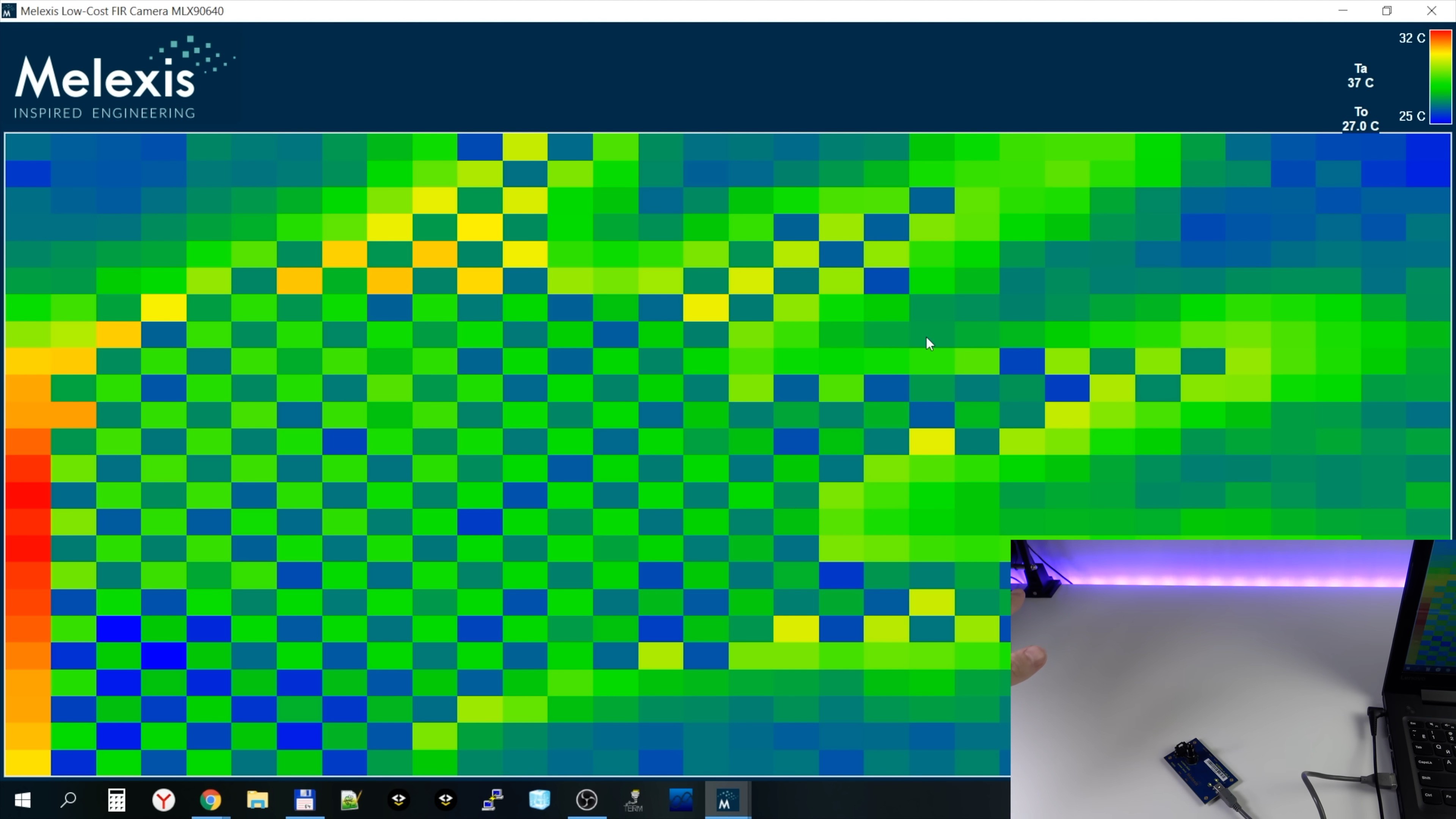
Now let's try a frequency of 32 Hz. As you can see, the image has become noisier:
This effect is mentioned in the documentation. The higher the frequency of collecting thermograms, the higher the thermal noise of the pixel. The dependence is approximately the following: the noise increases by 0.1 degrees with each Hz of frequency (for the sensor version with FOV 55).
It turns out that with a data collection frequency of 64 Hz, we can get up to 5-6 degrees of noise.
Therefore, high acquisition rates of thermograms are not suitable for domestic use, but this allows the sensor to be used in systems where it is necessary to quickly determine the appearance and location of a very hot or cold object (if the temperature of the object is very different from the ambient temperature).
The noise also depends on the temperature of the measured object. The lower the temperature of the object, the higher the noise. These are the physical properties of infrared radiation. A sensor with a 55 degree FOV has almost twice the noise as a sensor with a 110 degree FOV.
Pixels at the edges of the frame are noisier than pixels in the center of the frame. This is the effect of the optical properties of the lens.
In my thermal imager project, I used a thermogram collection frequency of 4 Hz. A very high frame refresh rate for home use is not very important. At the same time, the noise is within acceptable limits.
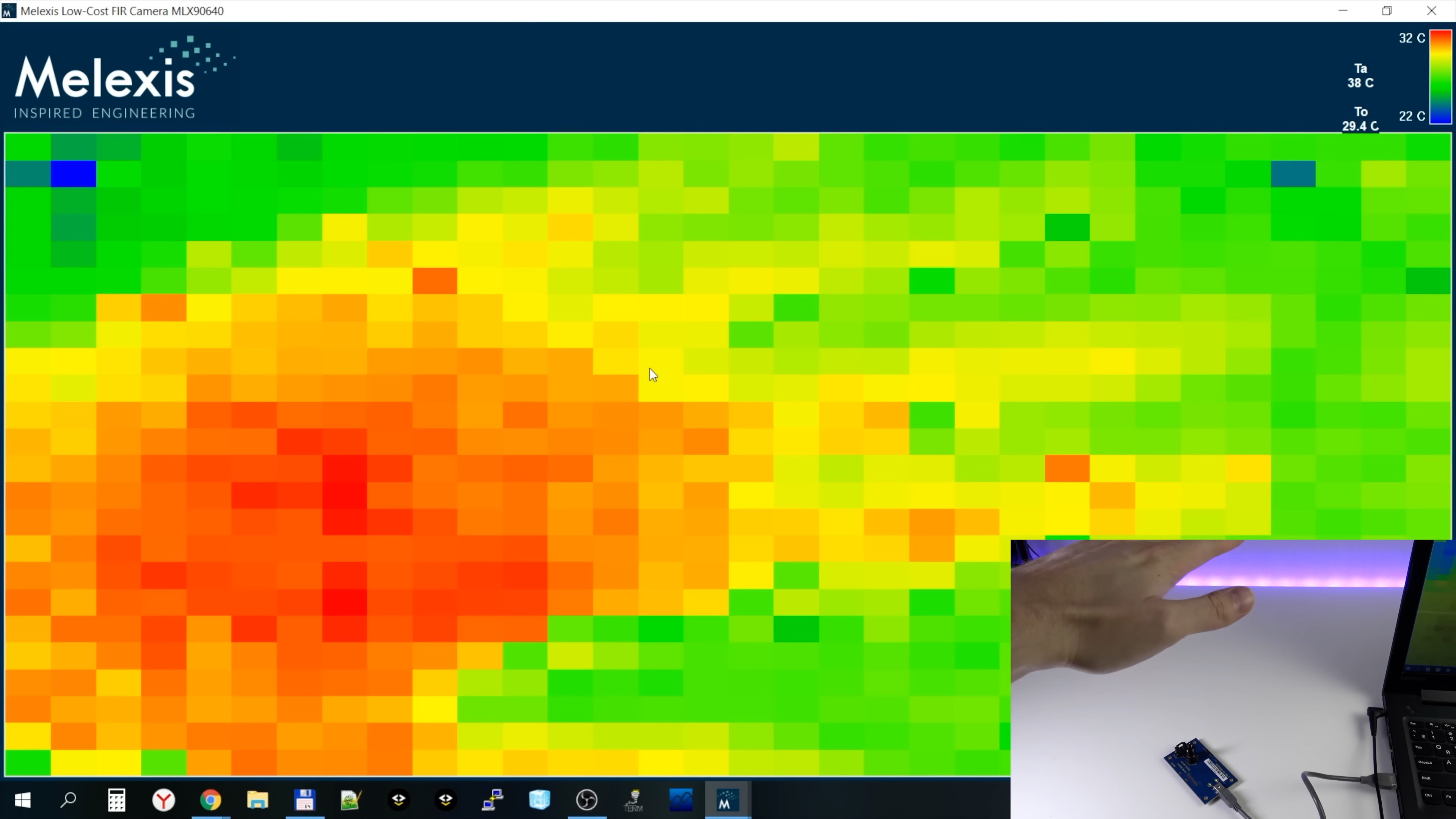
As you can see, the original resolution picture doesn't look good and needs some post-processing.
The software allows you to apply several types of filters to a thermal image, but, to be honest, all of them have very little effect. I tested them and didn't see much point in them.
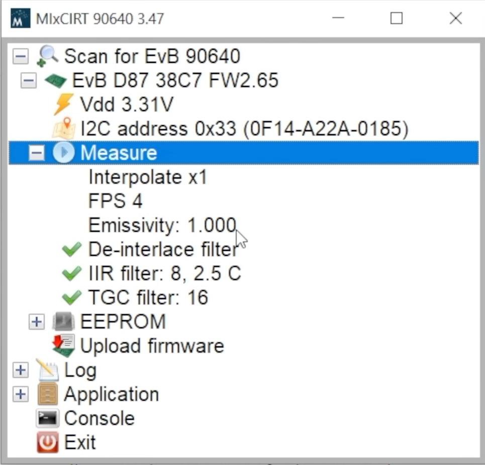
Image interpolation has a much stronger effect. It can also be enabled in the software. It significantly smoothes the image. In this case, of course, no new information appears in the frame, but the thermal image looks much better.
You can choose how many times the image will be enlarged during interpolation. Let's choose a magnification of 4 times (this is the maximum).
I don't like the way auto-scale selection works in the software. The temperature range for the scale must not decrease too low. In my thermal imager project, I use a different algorithm, which I will talk about very soon.
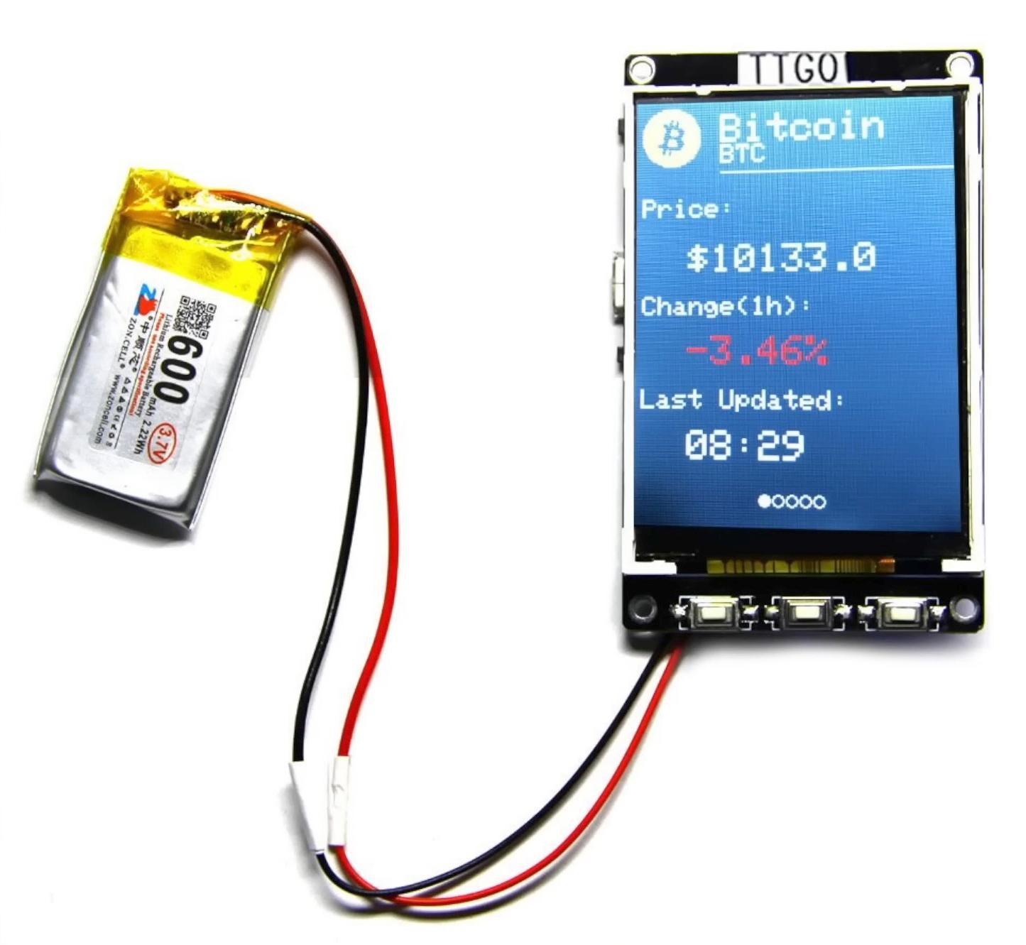
TTGO T4
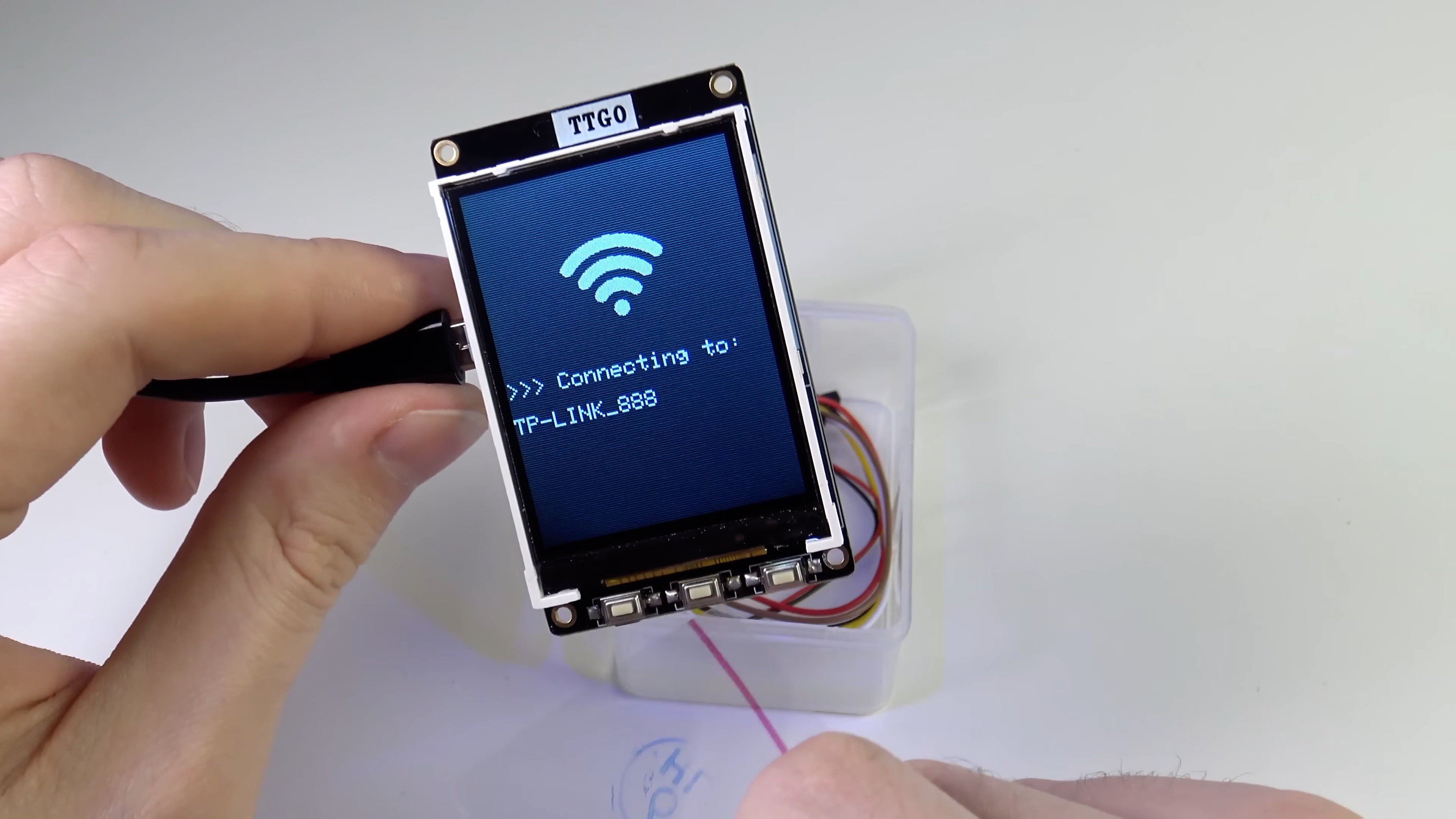
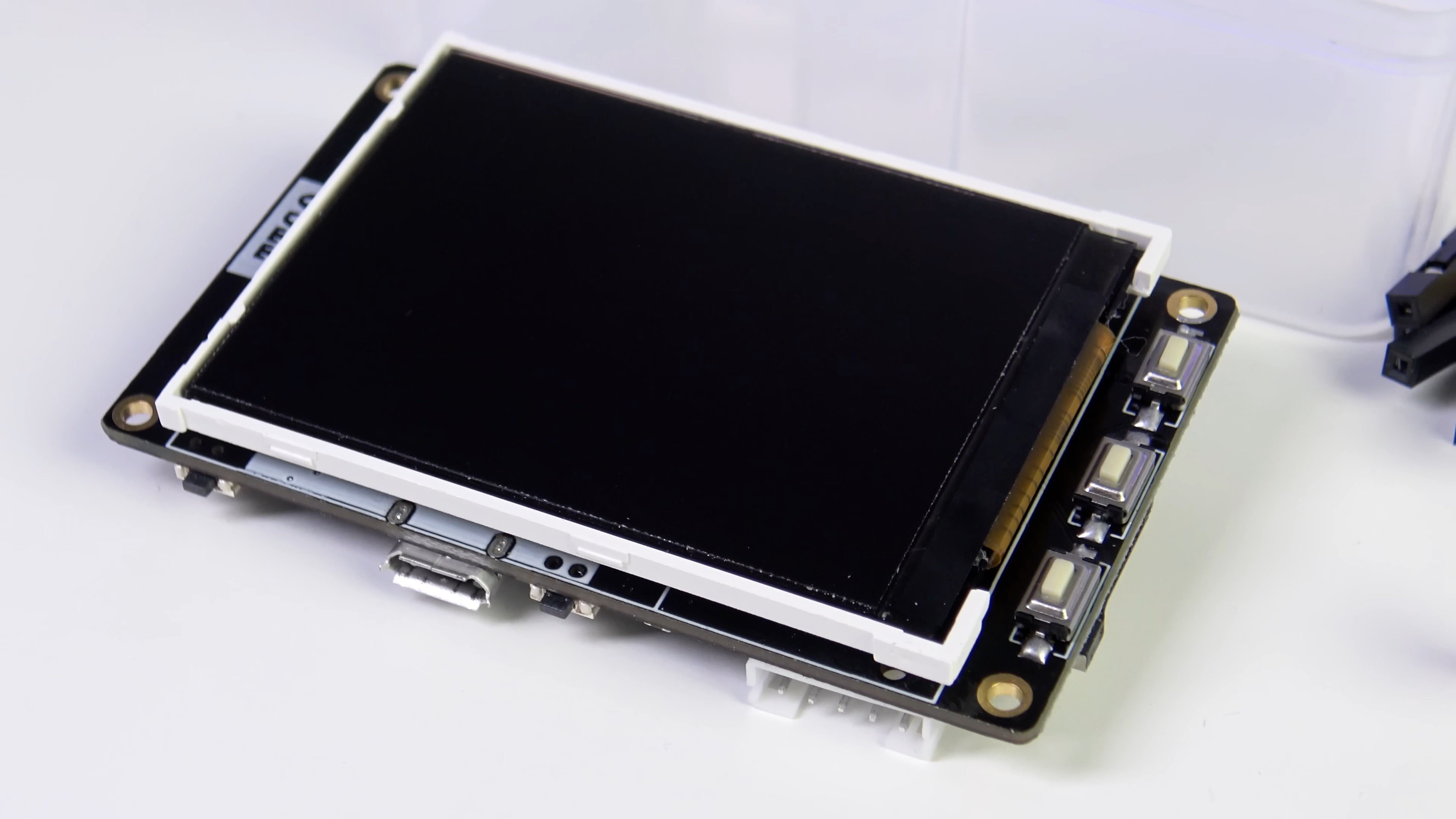
Surely some of you thought that I was using my own PCB with a display and buttons, but this is not so. I use a ready-made purchased product - a TTGO T4 board.
There are quite a few interesting devices in the TTGO series, I recommend you explore them all, but for a thermal imager project, the T4 board is the best.
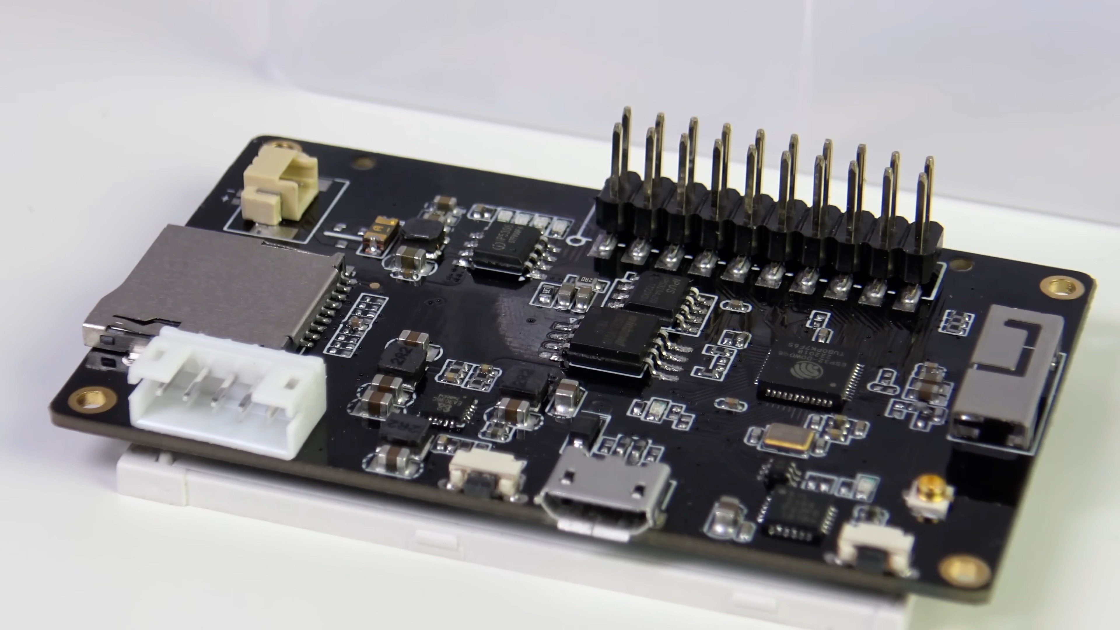
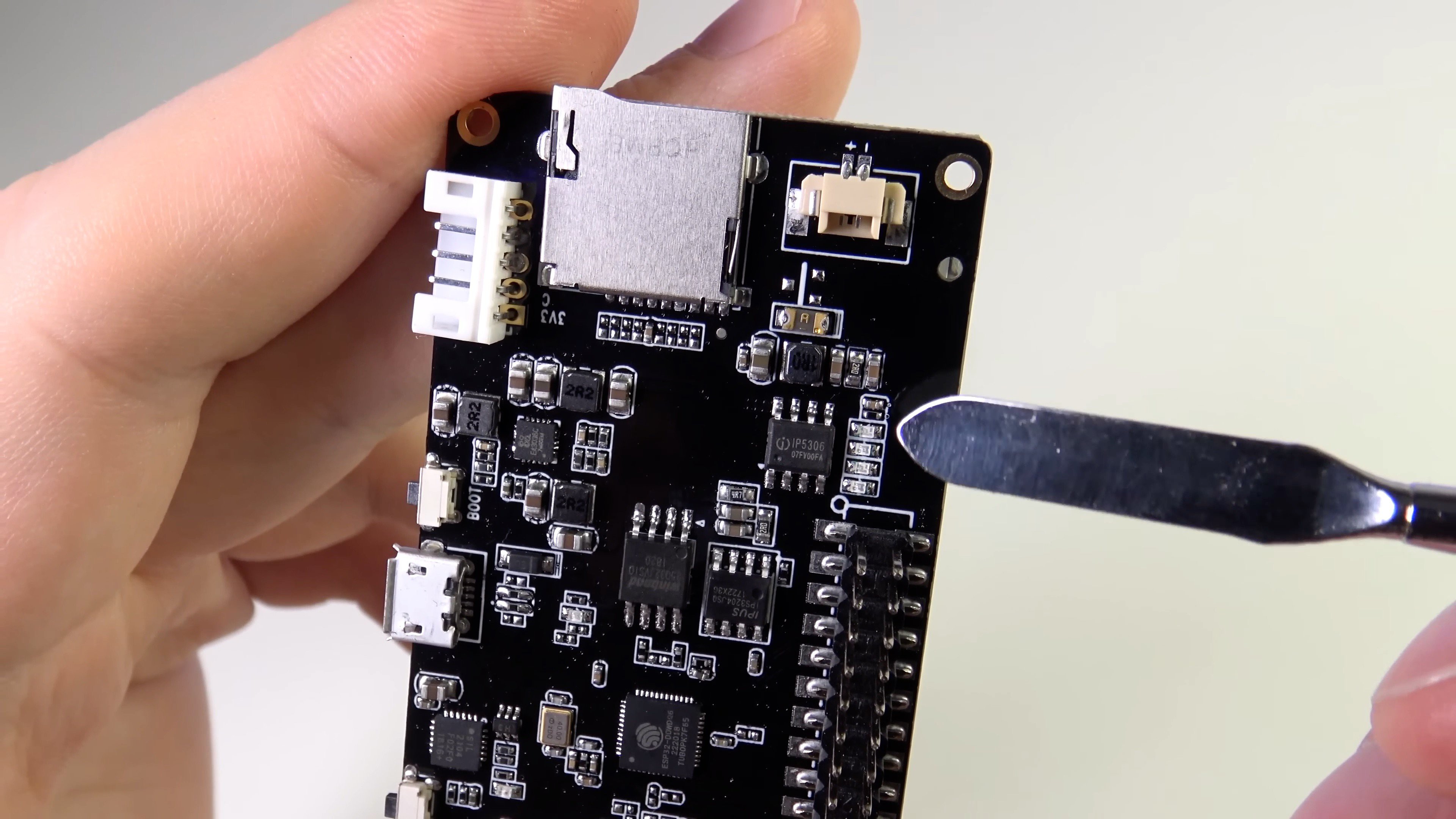
On the board are:
- 320x240 display with ILI9341 controller from ILITEK. The display does not use an IPS-matrix, but rather good TN. The display is connected to the ESP32 via SPI. ESP32 supports DMA when working with SPI, this is very convenient. At a 26 MHz SPI frequency, the full screen refresh time is 46 ms. There is no touchscreen, but there are 3 conveniently located buttons next to the display.
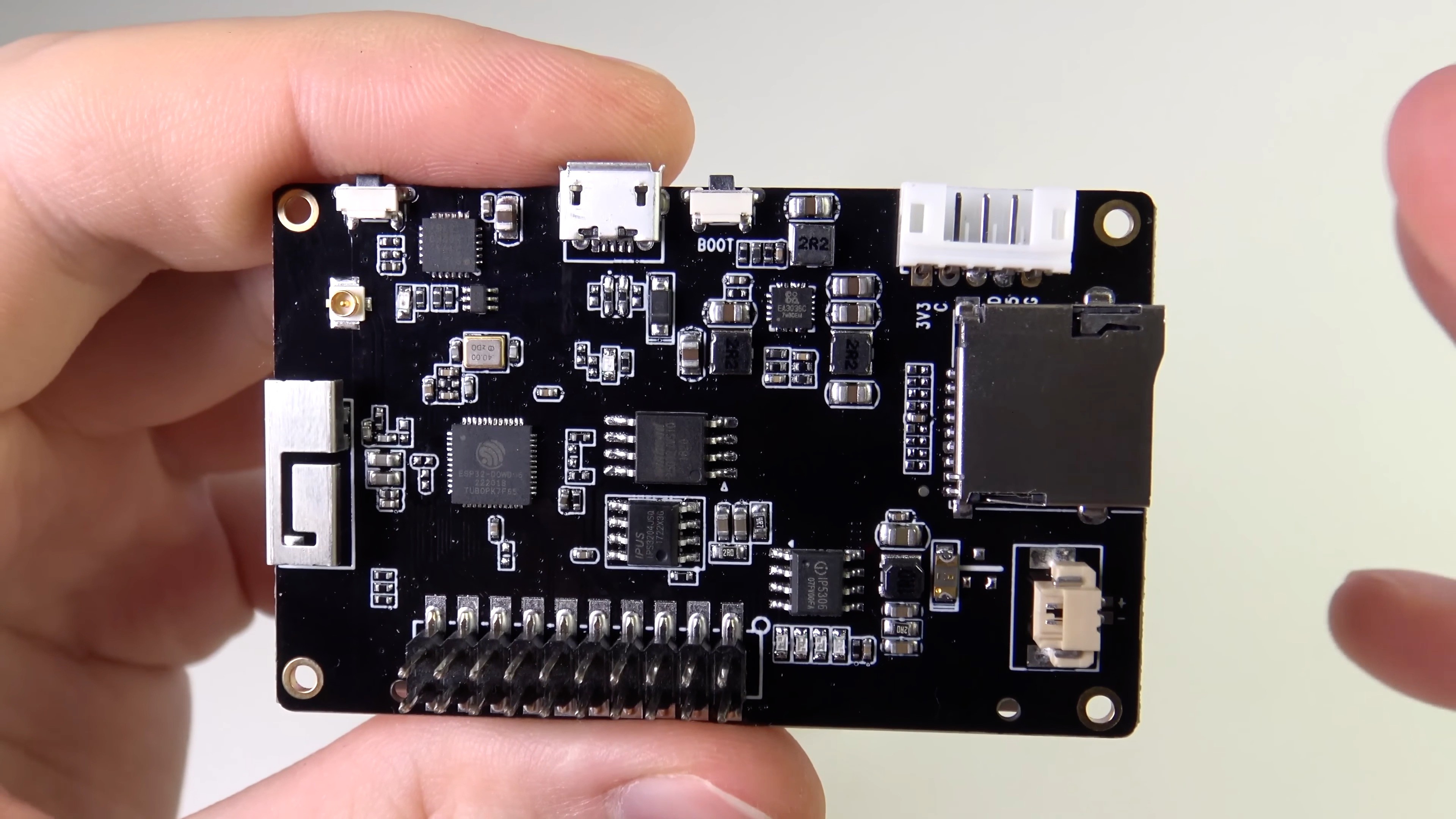
- ESP32 microcontroller with WiFi/BLE.
- SPI-flash Winbond W25Q32 (4 Mb).
- SPI PSRAM IPS3204 from IPUS (4 Mb). This is pseudo-static RAM, i.e. inside is a cheap dynamic RAM and a controller that refreshes it and implements access to it via SPI. ESP32 hardware supports working with such memory chips and for the programmer everything looks simple and transparent.
- WiFi/Bluetooth antenna and external antenna connector.
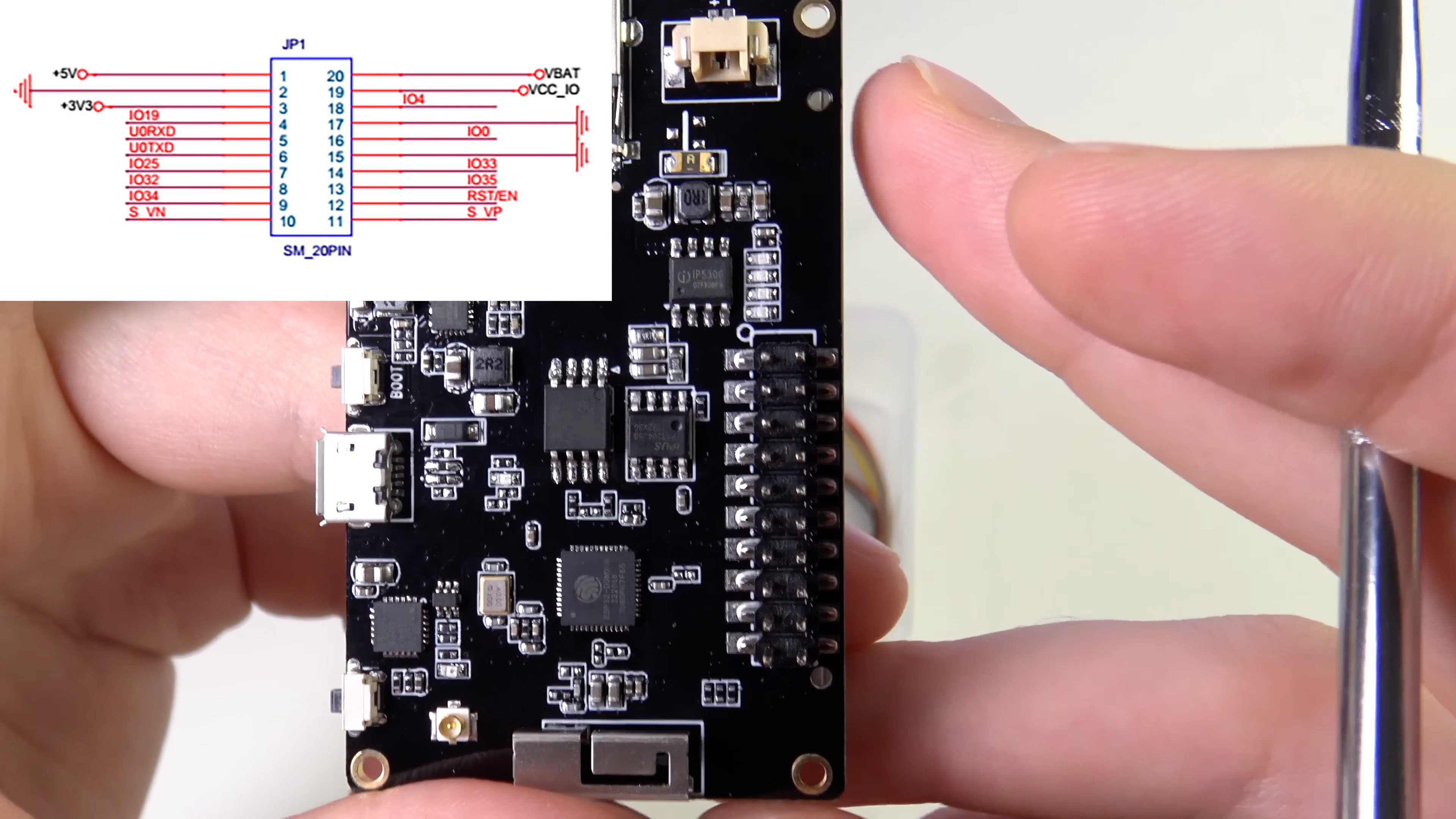
- 2x10 pin expansion connector. On one of the T4 boards, this connector was poorly soldered, and for a long time I could not understand why everything was buggy for me. White connector (4 or 5 pins in different T4 versions) - for connecting GROVE format expansion modules (connected via i2c). A short cable is included.
- Slot for microSD cards.
- microUSB connector for powering the device and charging the battery, as well as for connecting to the UART ESP32 via the USB-UART bridge CP2104 from SiLabs. This port can be used to flash the ESP32 and debug software via the console.
- BOOT button to put ESP32 into bootloader mode.
- POWER button to turn on/off the thermal imager. The fact is that the board contains the IP5306 chip from Injoinic - this is a battery charging controller for POWER-BANK. Such devices often have an on/off button, and the POWER button is connected as such a button. Those. The IP5306 controls the on/off of the device using the POWER button. Pressing the POWER button once turns on the power and resets the microcontroller if the device is already on (the button also closes the RESET microcontroller to ground). Pressing the POWER button twice turns off power to the device.
- 2 pin connector for connecting Li-ION battery (connects to IP5306). A short cable is included.
- 4 blue LEDs for displaying the battery charge level. It is also possible to replace the IP5306 on the board with IP5306-I2C, which will allow you to read the battery status via I2C. But in my project, I did not do this, and I determine the charge level by the voltage on the battery.
- Power scheme. Input voltage and battery voltage are connected to the IP5306 charge controller. It also generates a 5V voltage, which is connected to an EA3036C switching converter from EverAnalog, which generates a 3.3V voltage to power all components.
There are also disadvantages:
- Not a very good way to mount the display on 2-sided tape. Moreover, adhesive tape in different deliveries was used in different thicknesses, and if it was thin, then the contacts of the GROVE connector protruded the display from the board.
- Switching power from USB to battery sometimes resets the ESP32. This may have been fixed in new revisions of the T4 board.
- In the off state, a very slow, but still discharge of the battery continues. This may have been fixed in new revisions of the T4 board.
Hardware V1.0
In this chapter, I will talk about the assembly of the device without a case with a capacious battery, it looked like the first version of the device. Later I reviewed some solutions and made the case, but I will talk about this later.

TTGO manufacturer recommends using a 600 mAh battery:
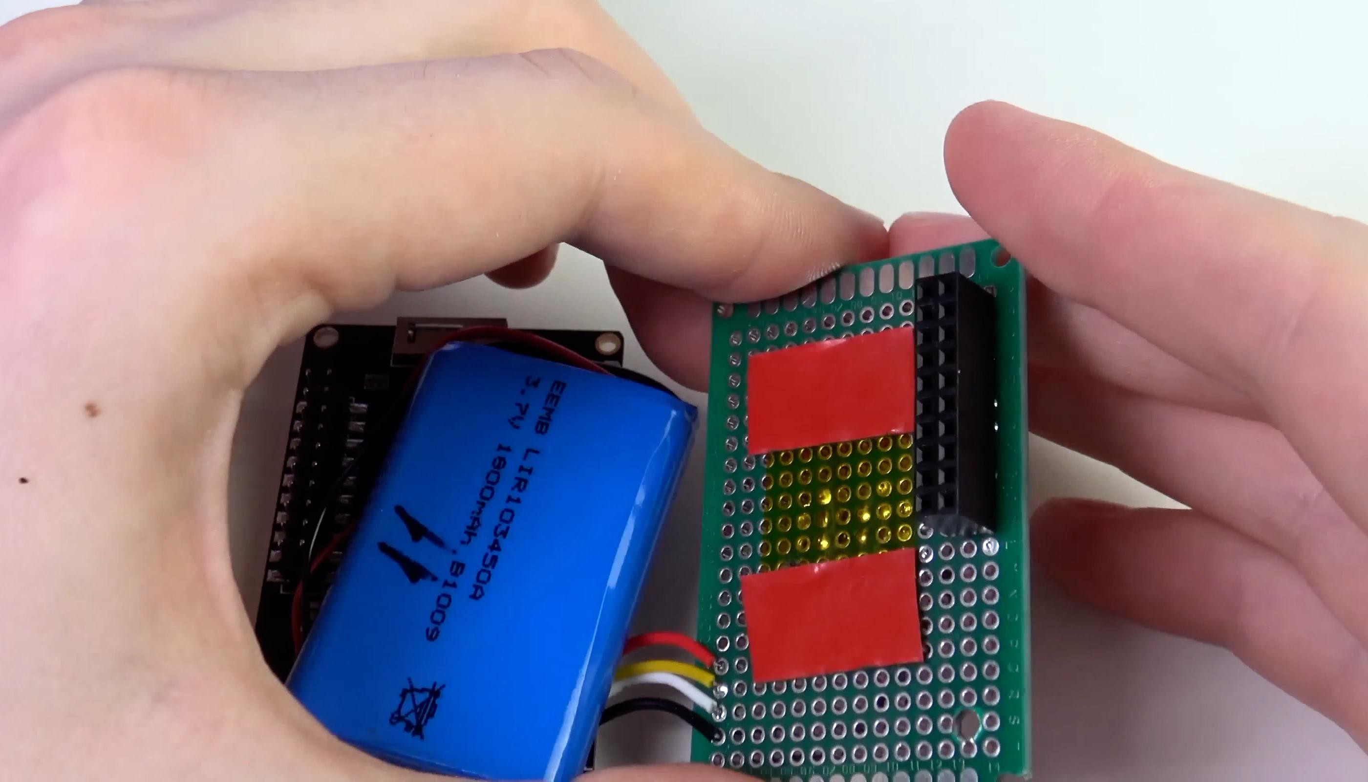
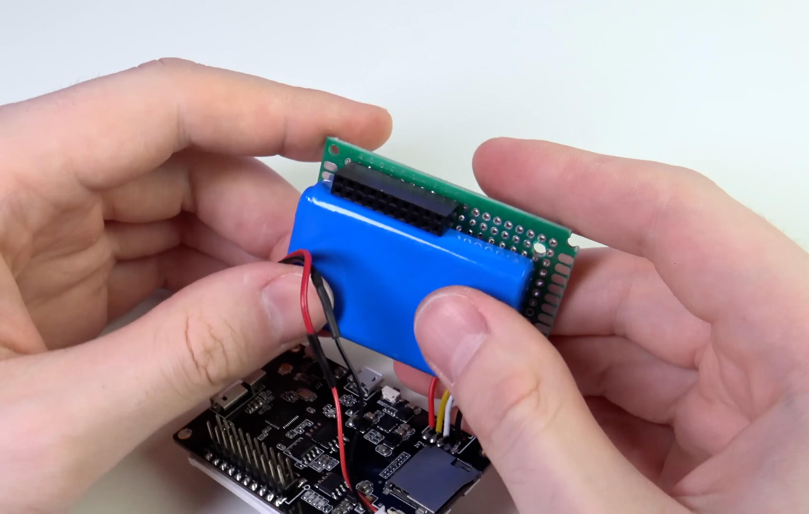
I decided to use the LIR103450A battery with a capacity of 1800 mAh.
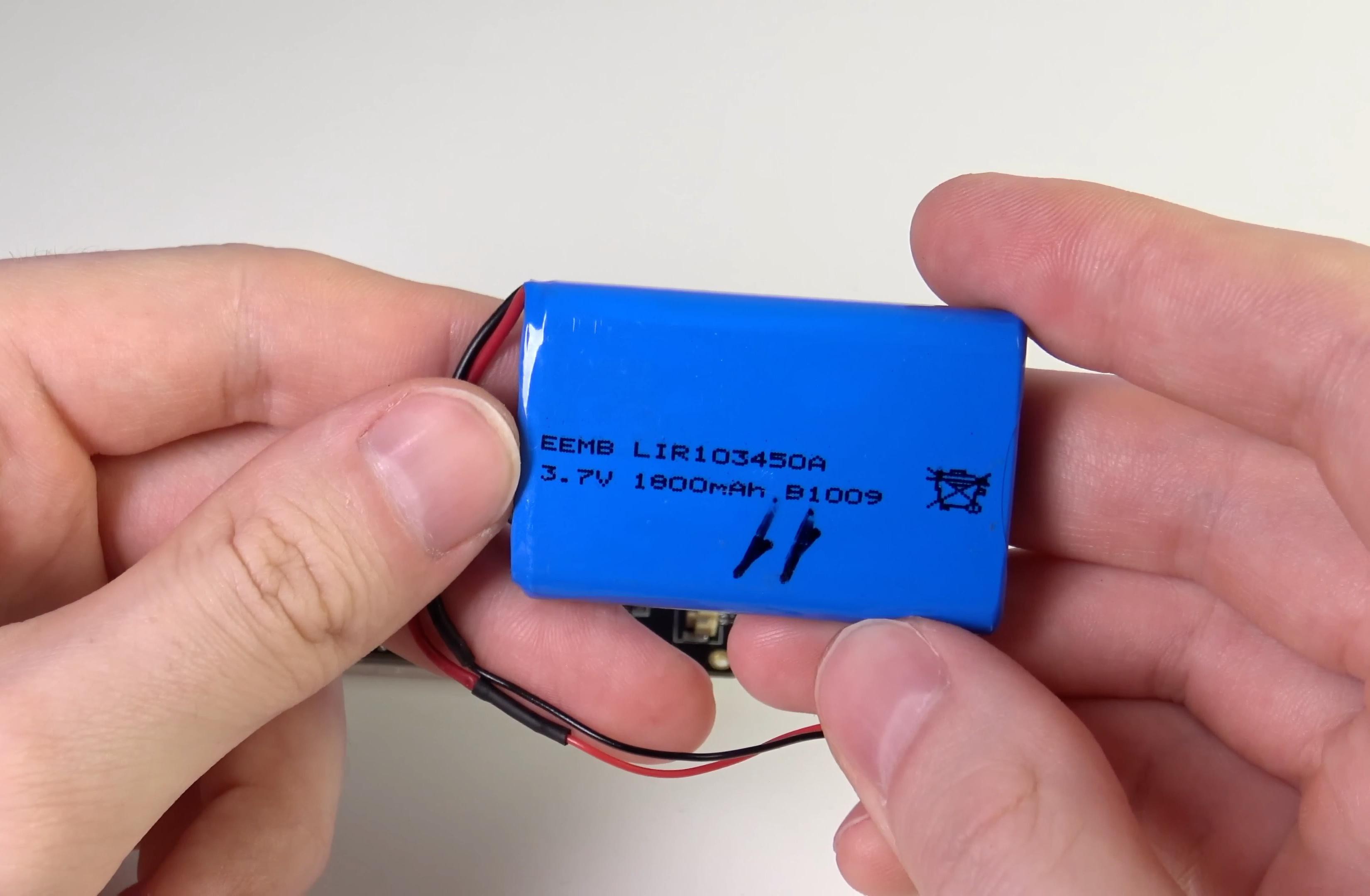
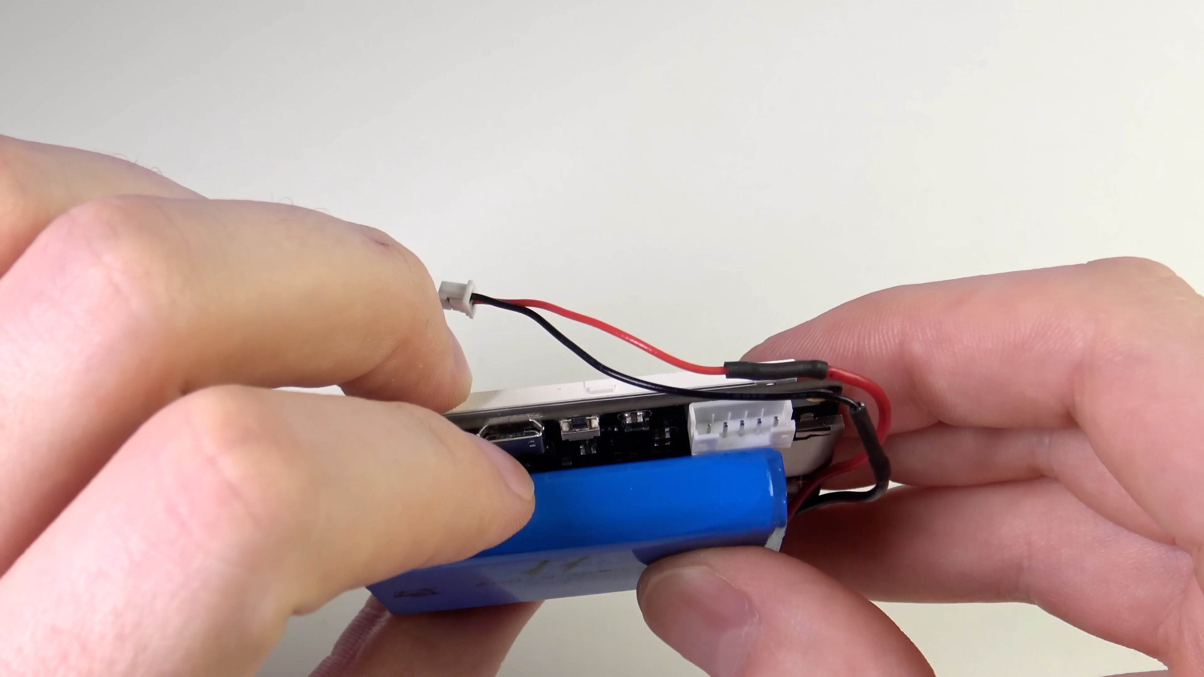
This battery is perfect in size. The only thing that prevents it from placing it close to the T4 board is a white expansion connector for GROVE modules (I removed this connector from the board).
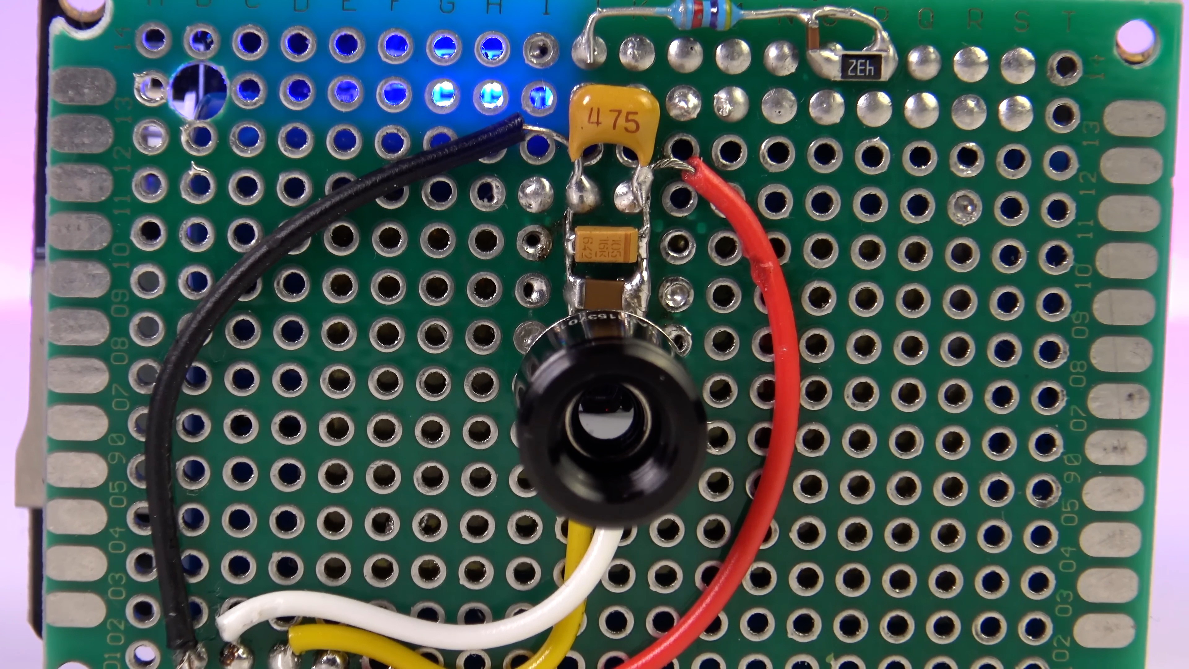
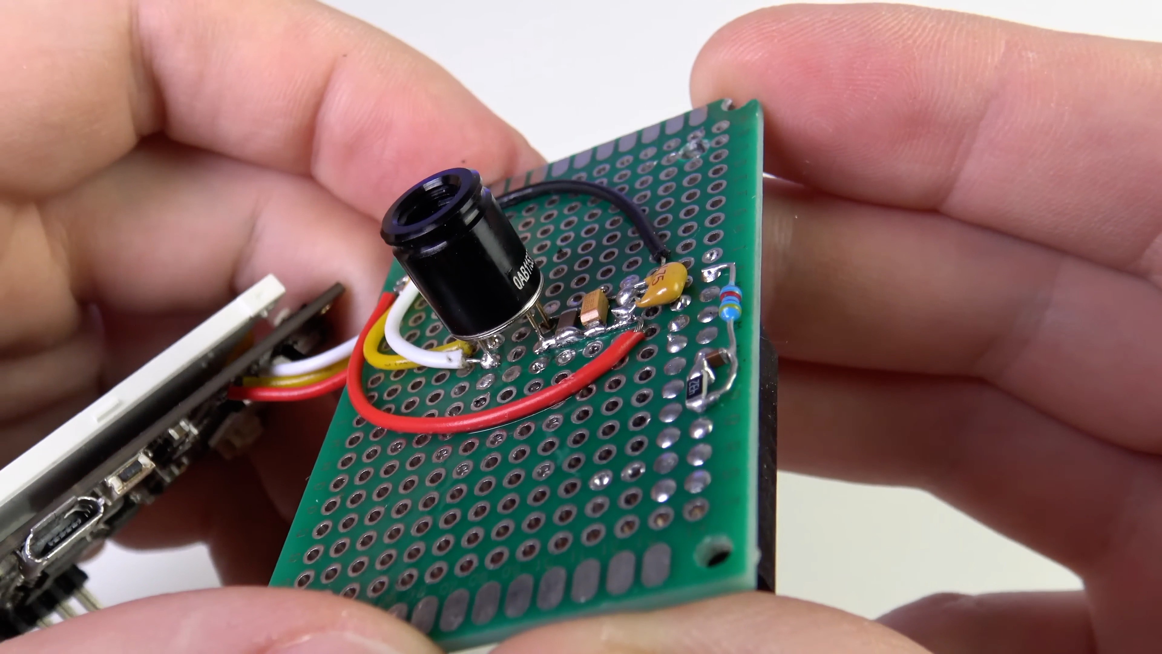
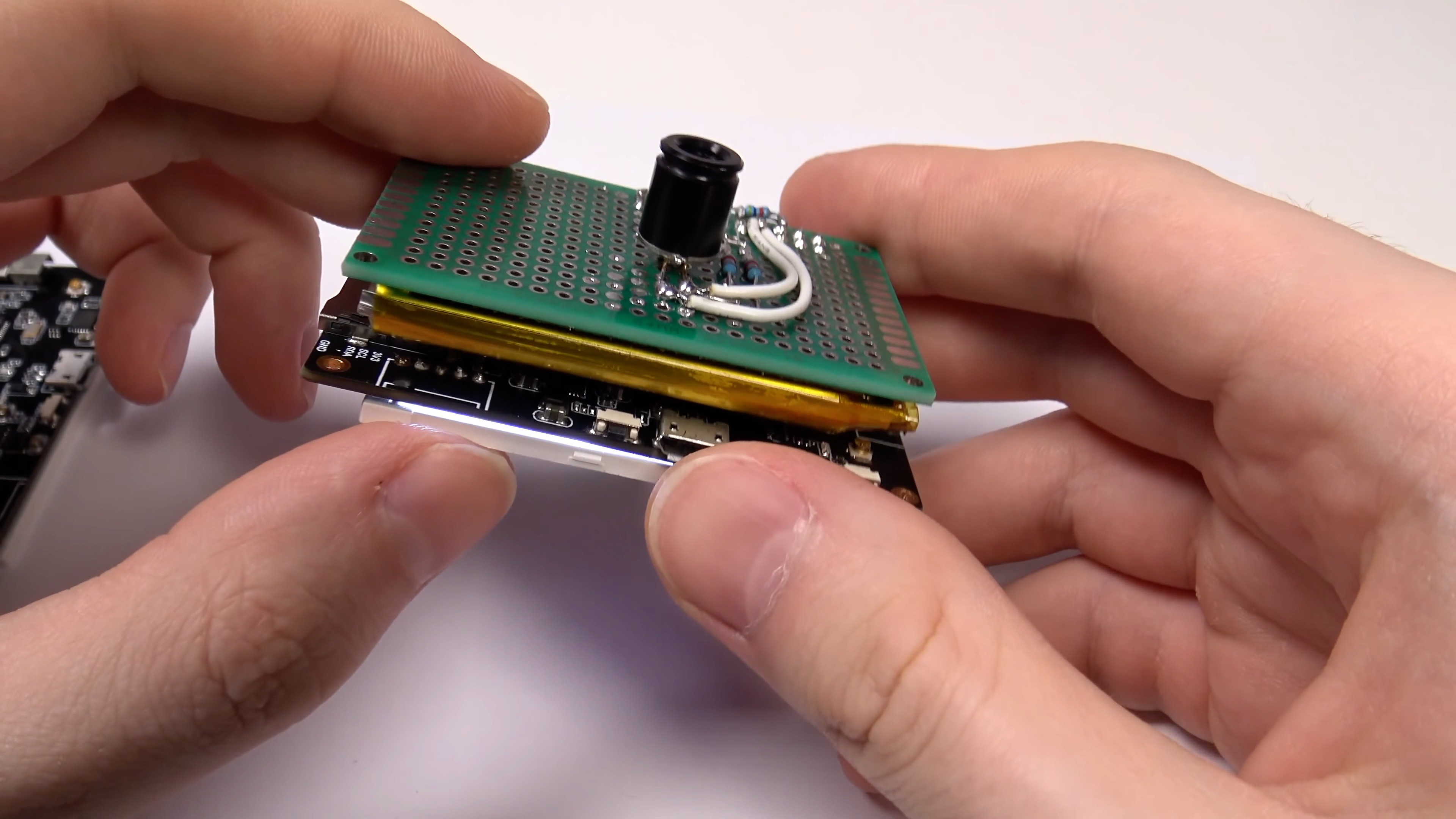
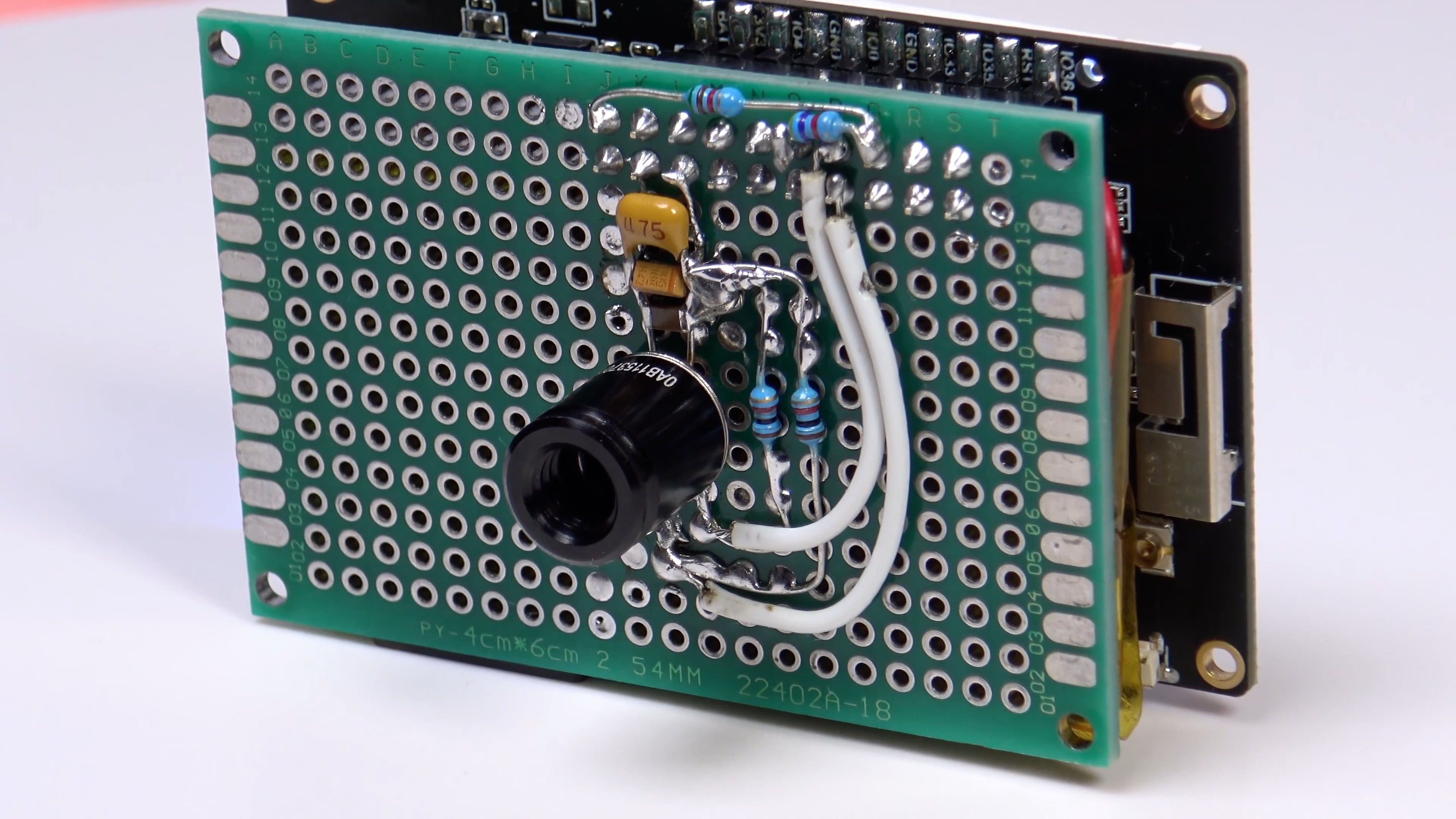
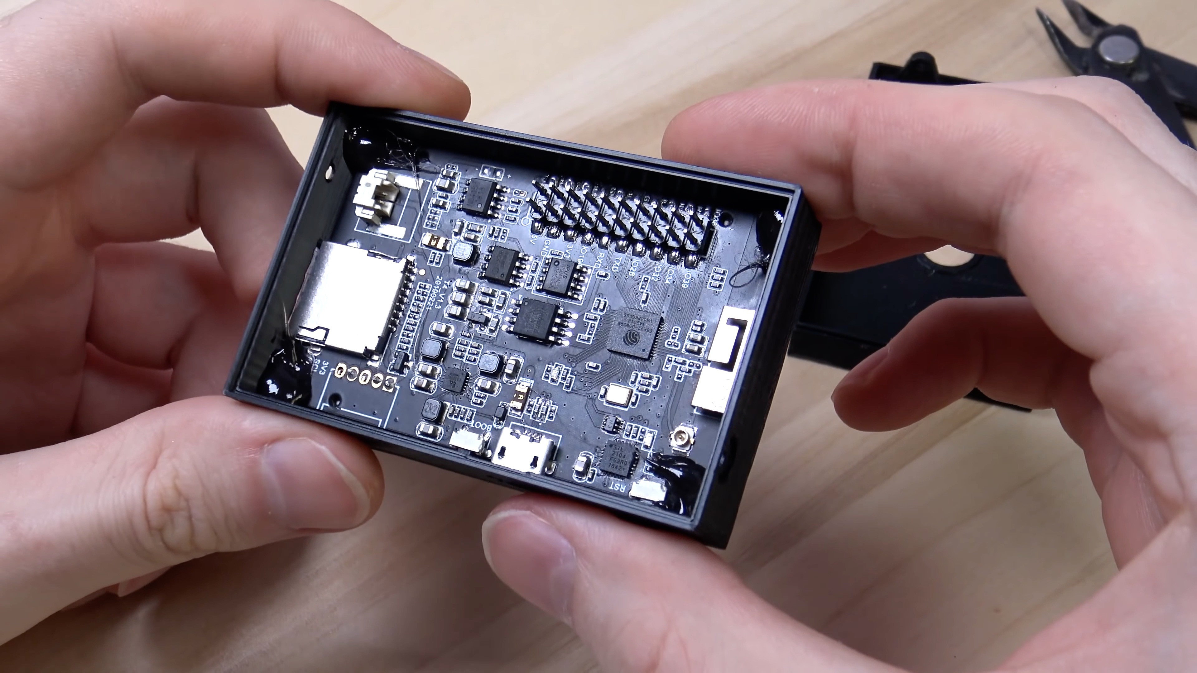
Next, I prepared the backboard. It does not have many connections at all, so I used the usual breadboard of a suitable size. It is located on it:
- MLX90640 sensor
- Sensor power filter condensers
- 2x10 connector for connecting to the TTGP T4 expansion connector.
- Resistant divider for measuring the battery voltage.
I glued the battery to the layout using double-sided tape.
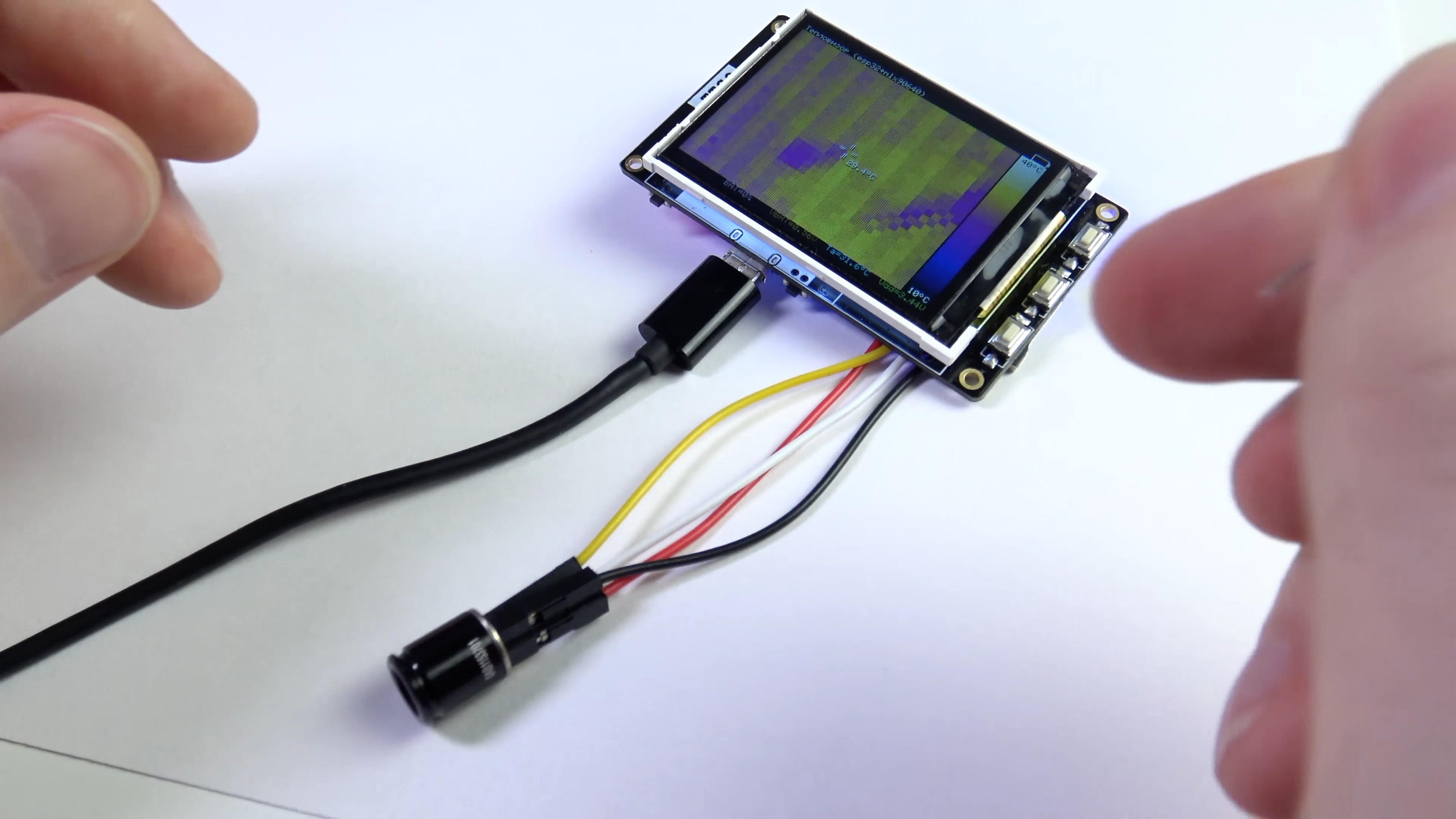
I connected the sensor with wires to the contacts of the GROVE connector. This connection is not detachable.
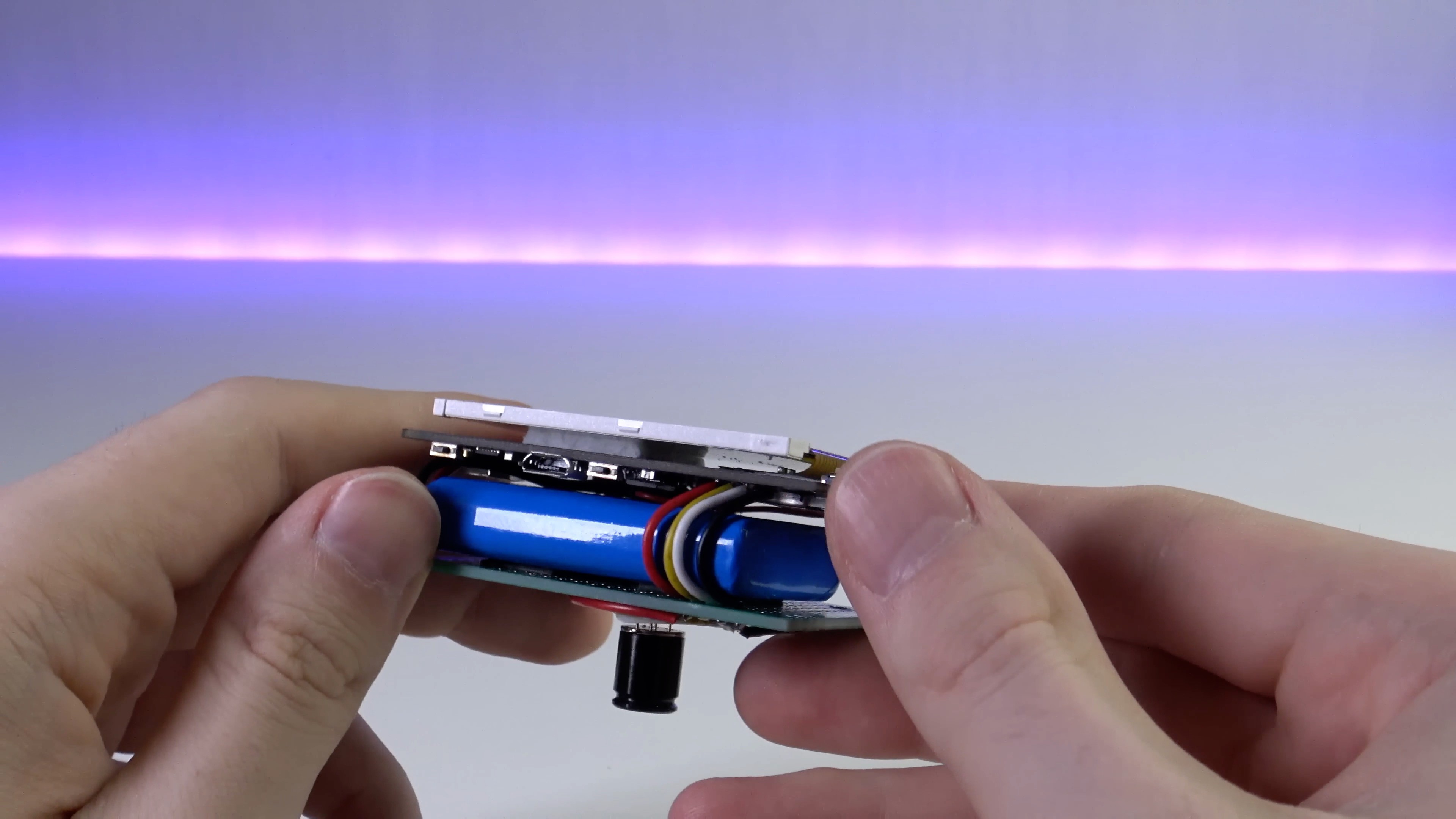
After that, the battery is connected by two wires to the TTGO T4 board. Next, the expansion connector 2x10 is connected. The device is almost assembled, it remains only to additionally fasten 2 boards to each other, I used screeds for this.
Firmware V1.0
When writing firmware, I used the SDK ESP-IDF from Espressif systems. This is a very powerful SDK. It includes FreeRTOS, so that the thermal imager works on it.
ESP32 has 2 identical CPU cores, but only 1 core is used in my project, all tasks are performed on it.
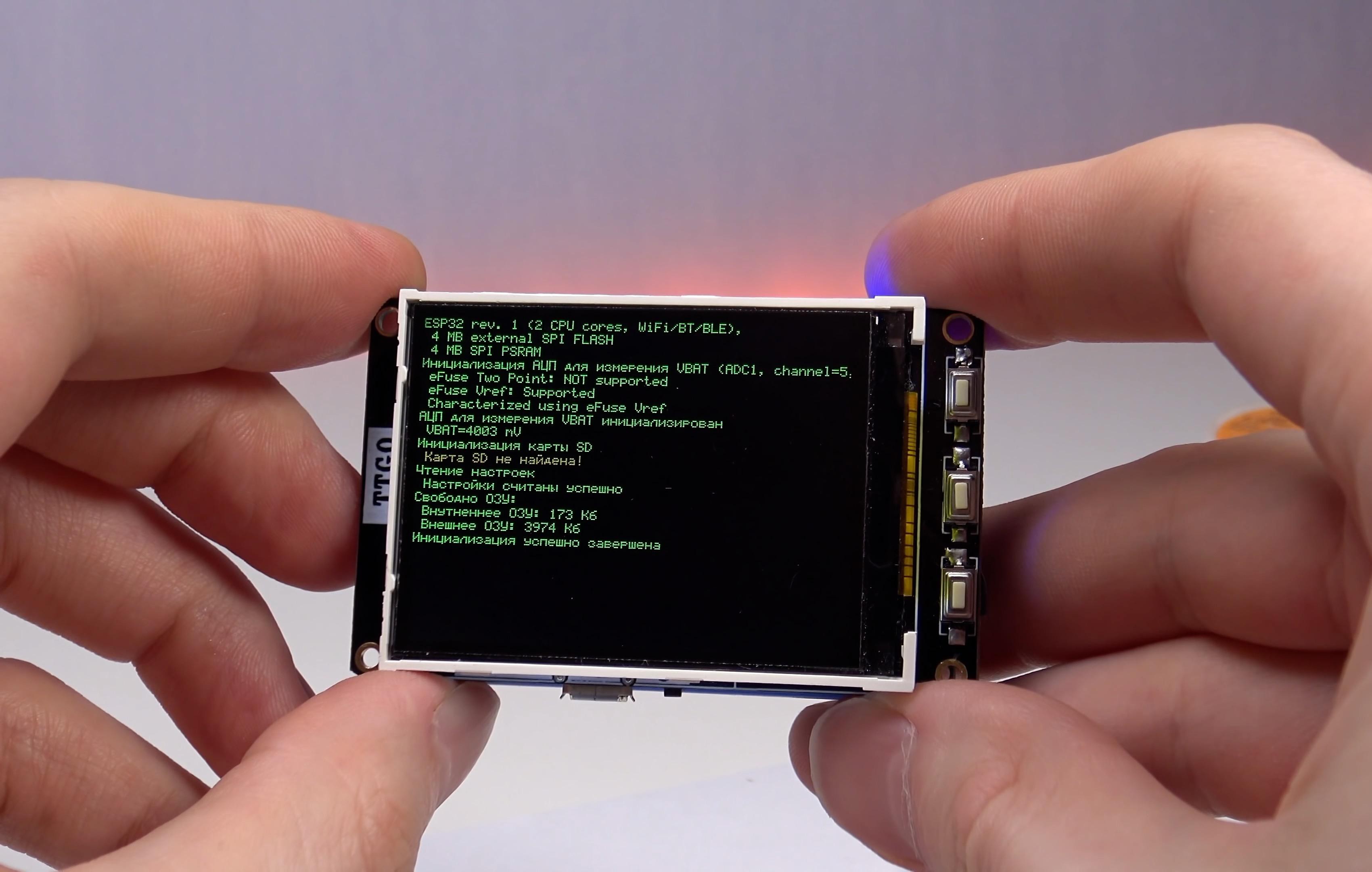
During the load, debugging messages on the device screen and to the USB console are displayed. Error messages are displayed in red, warnings are yellow, and messages without errors and warnings are green.
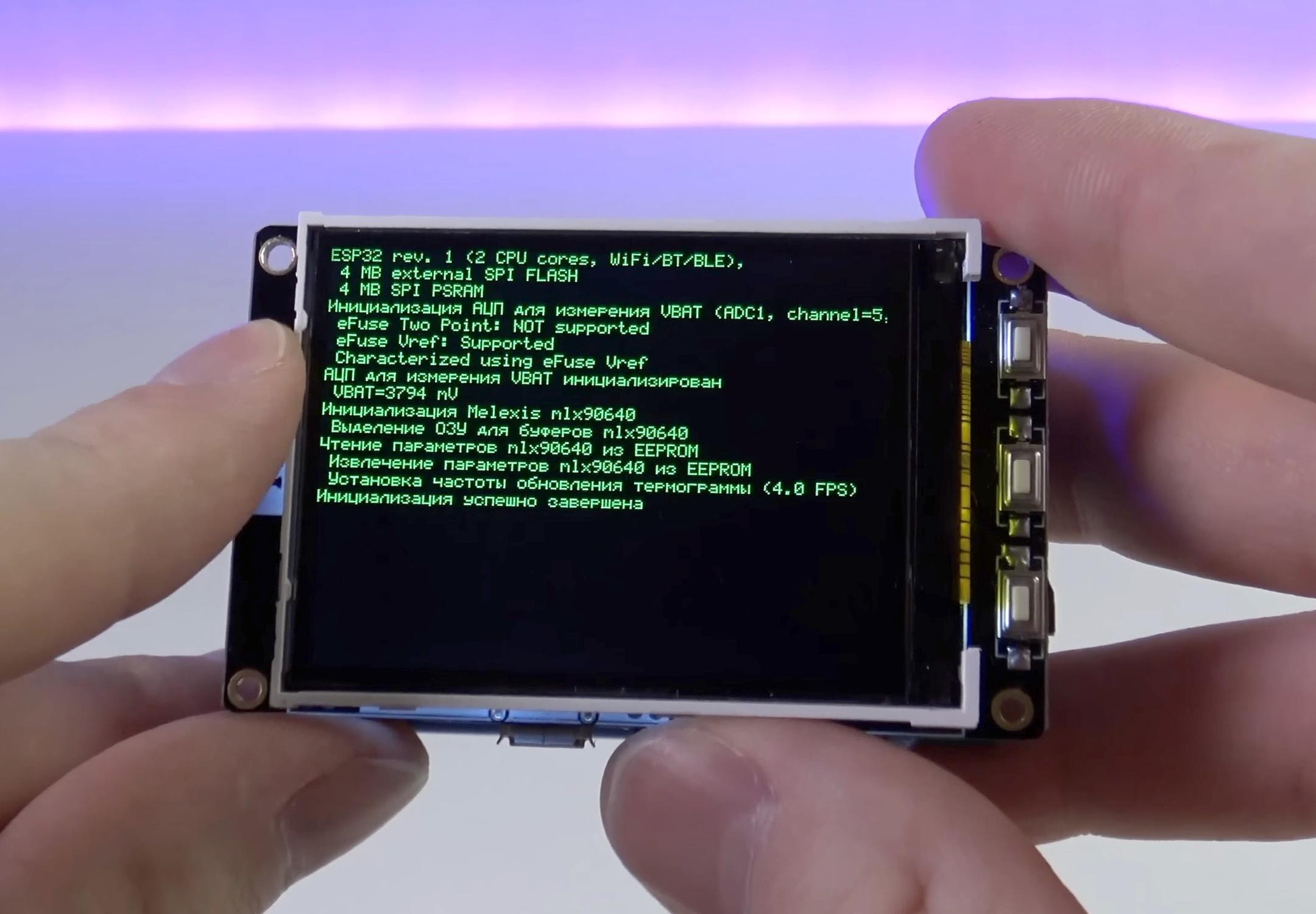
As you can see, in my firmware I use the Russian language everywhere, but you can easily change it, because I publish all source codes.
To transmit the image to the display frame, I use SPI in DMA mode, the ESP-IDF has a very simple API for this, so this work was not difficult. For a long time, for my projects I wrote a small light graphic library (dispcolor) and therefore I used it in the project.
To work with MLX90640, I used library from the sensor manufacturer.
https://github.com/melexis/mlx90640-library
It implements everything necessary, I only needed to implement the functions of reading/recording 2-byte registers via i2C.
The library allows you to read and process the thermogram in 2 versions: in conditional units or in degrees of temperature. The second option is a little more complicated. The thermogram calculation methodology is described in the Melexis documentation. In the final thermogram, the faulty sensor pixels are already adjusted if they were detected in the matrix in the production of the sensor.
Now for the calculation, constant surface emissivity is used = 0.95, but I will make it changed through the menu in firmware 1.1.
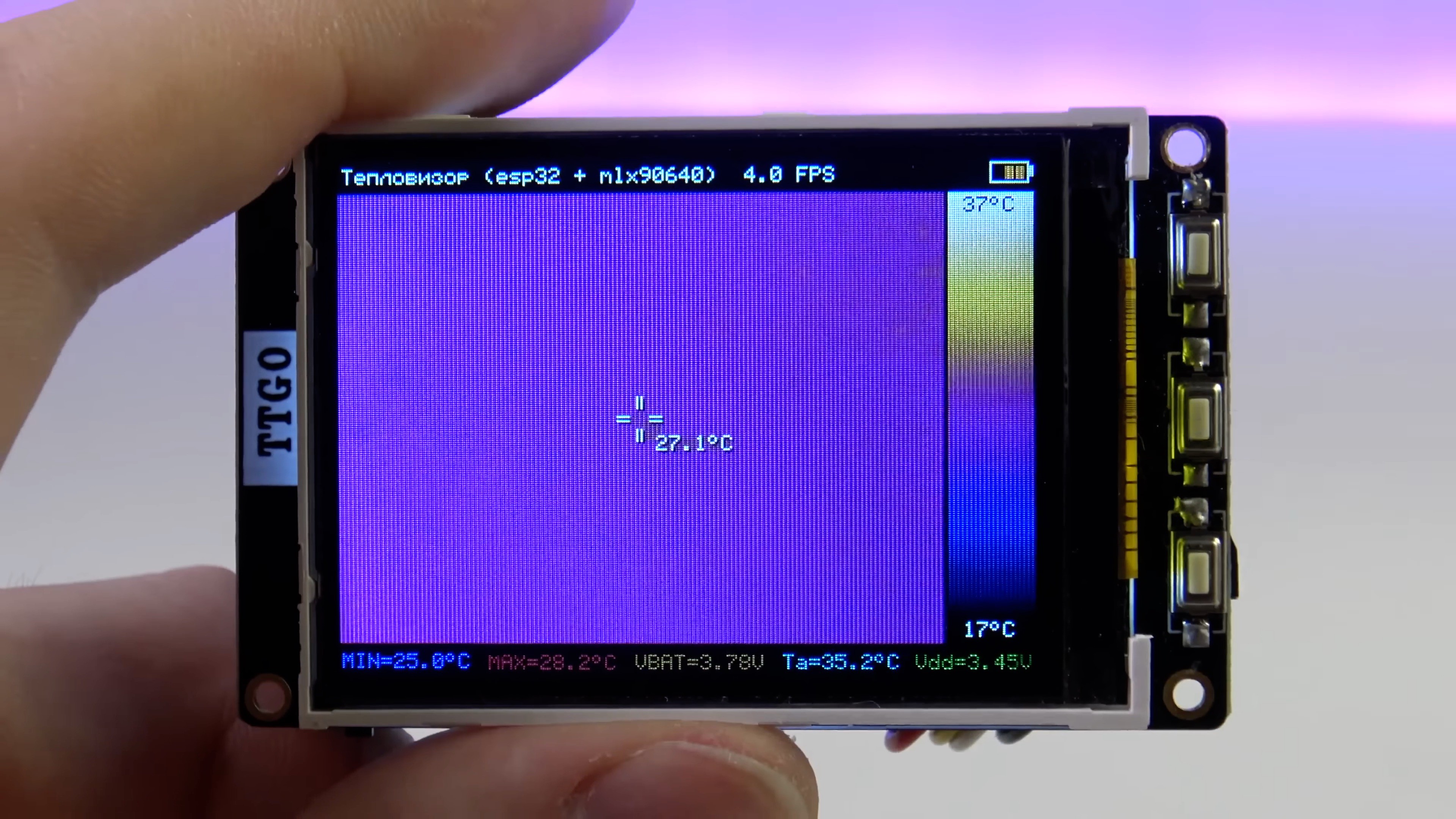
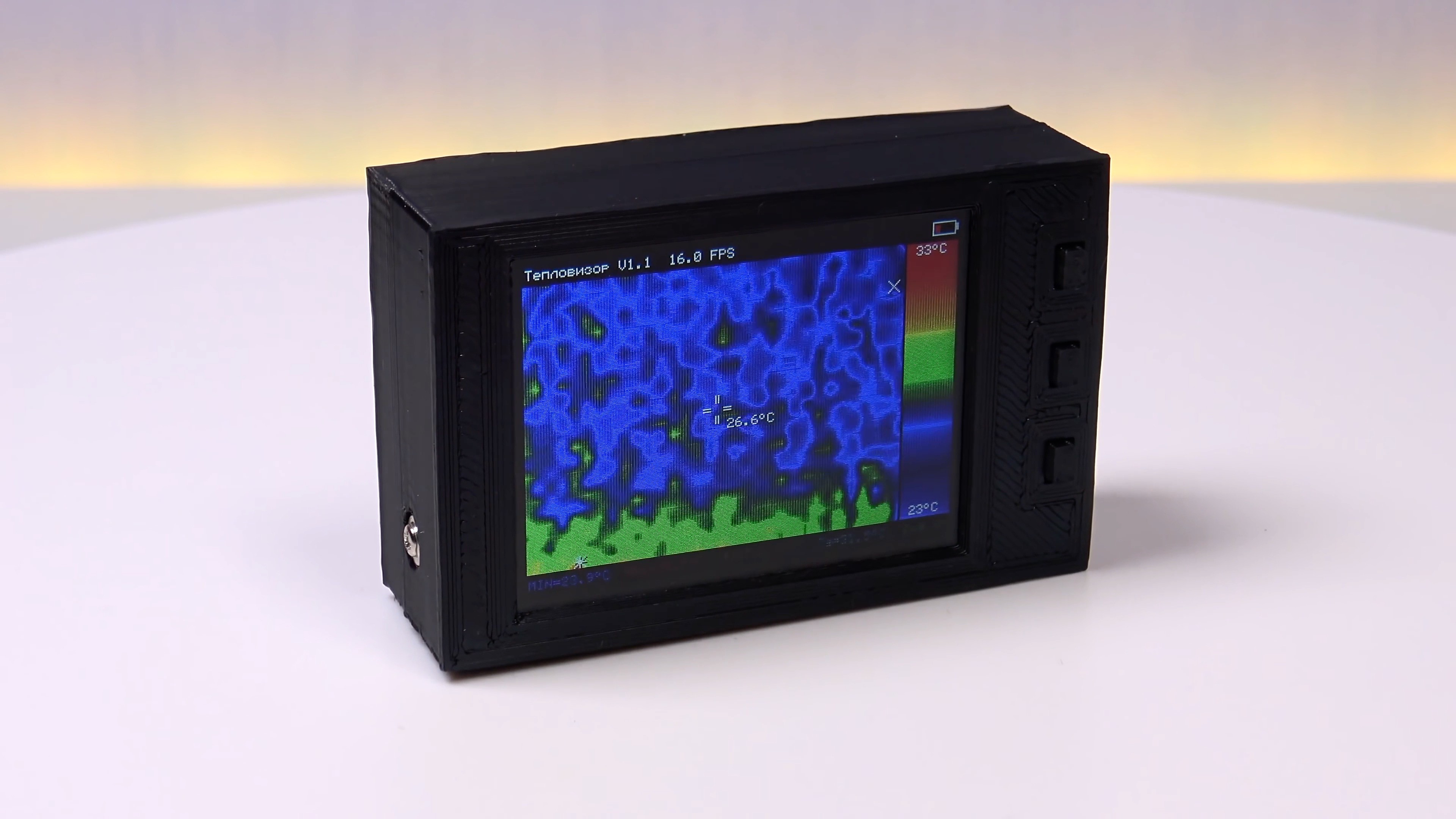
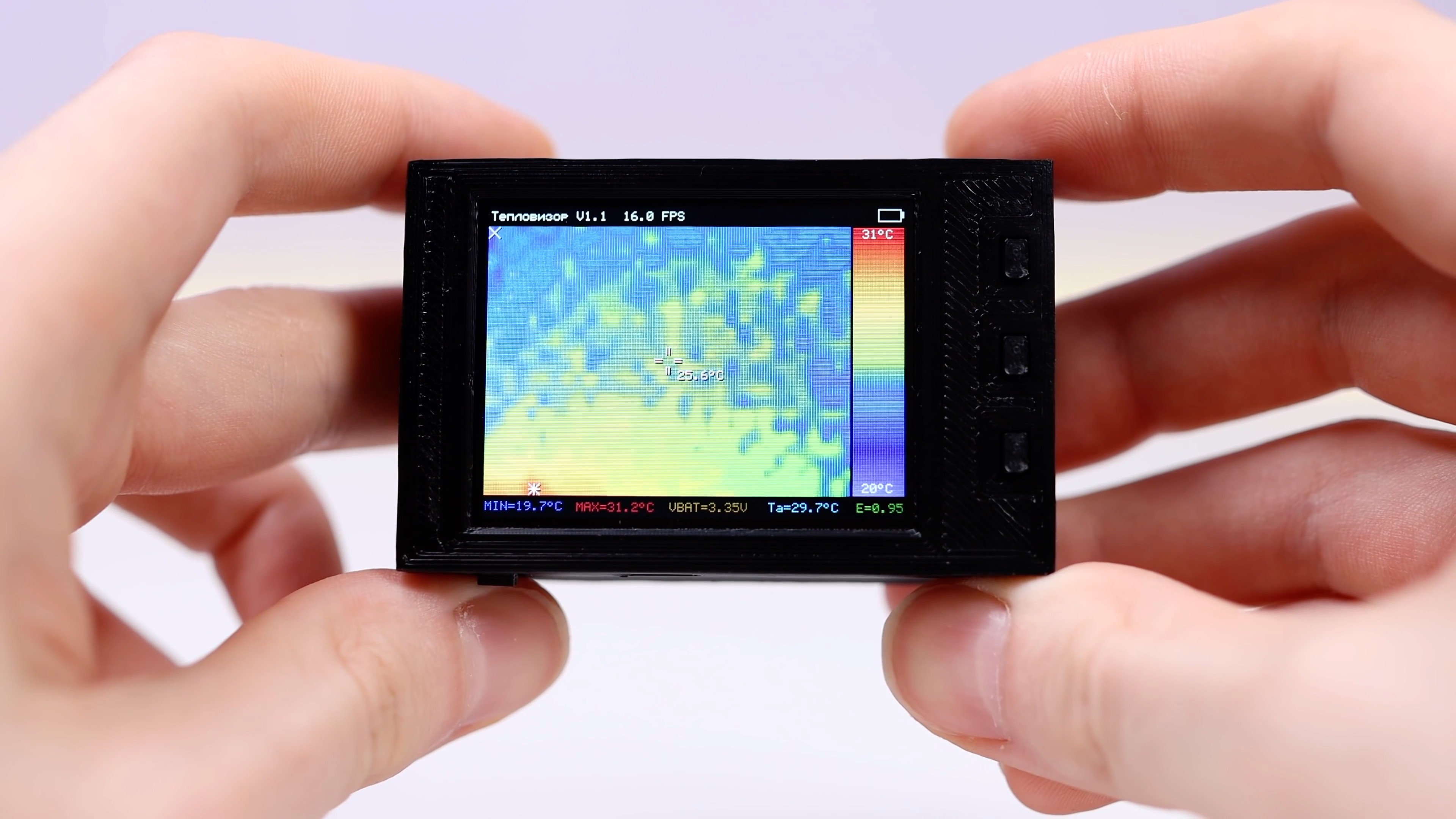
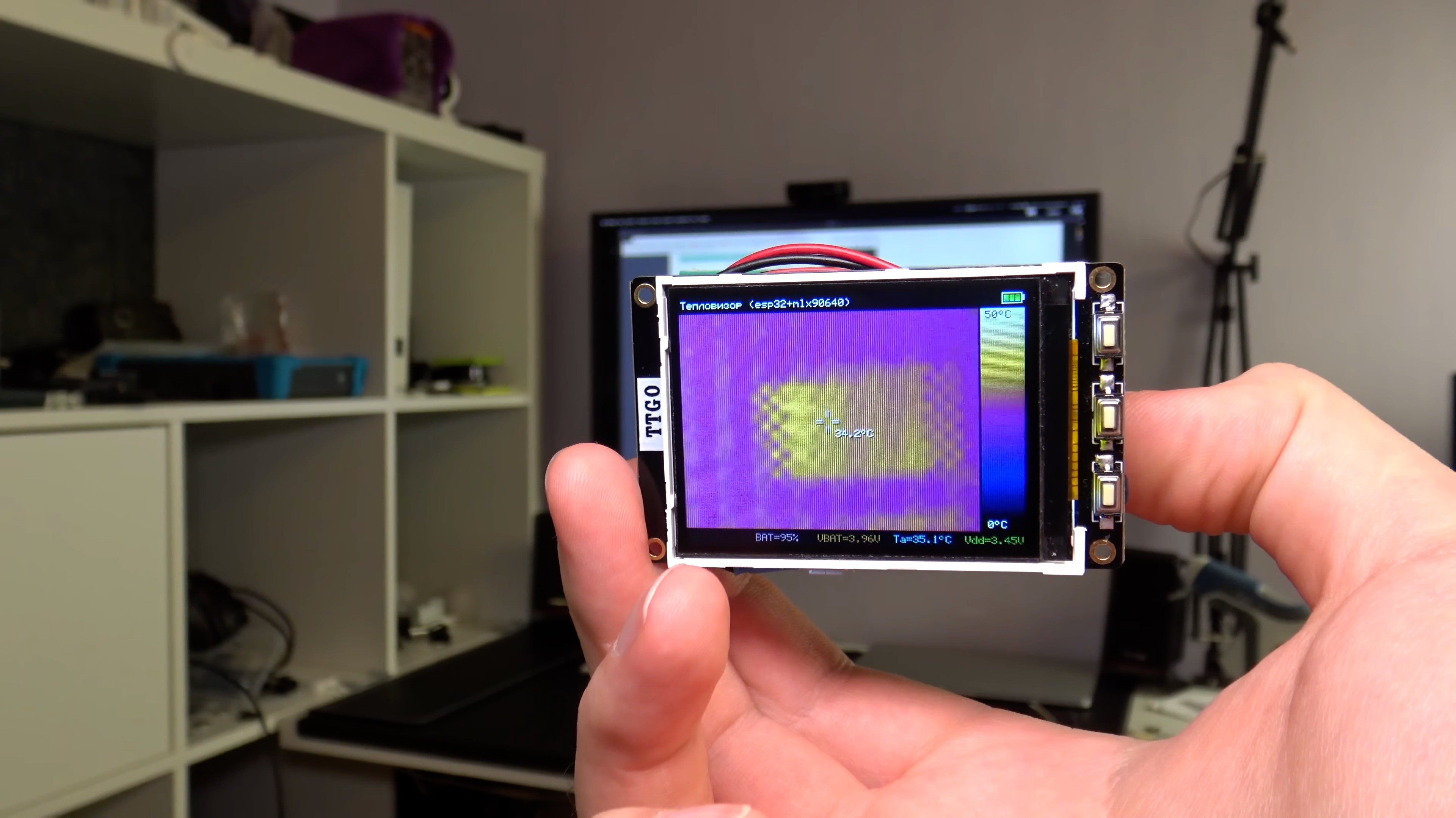
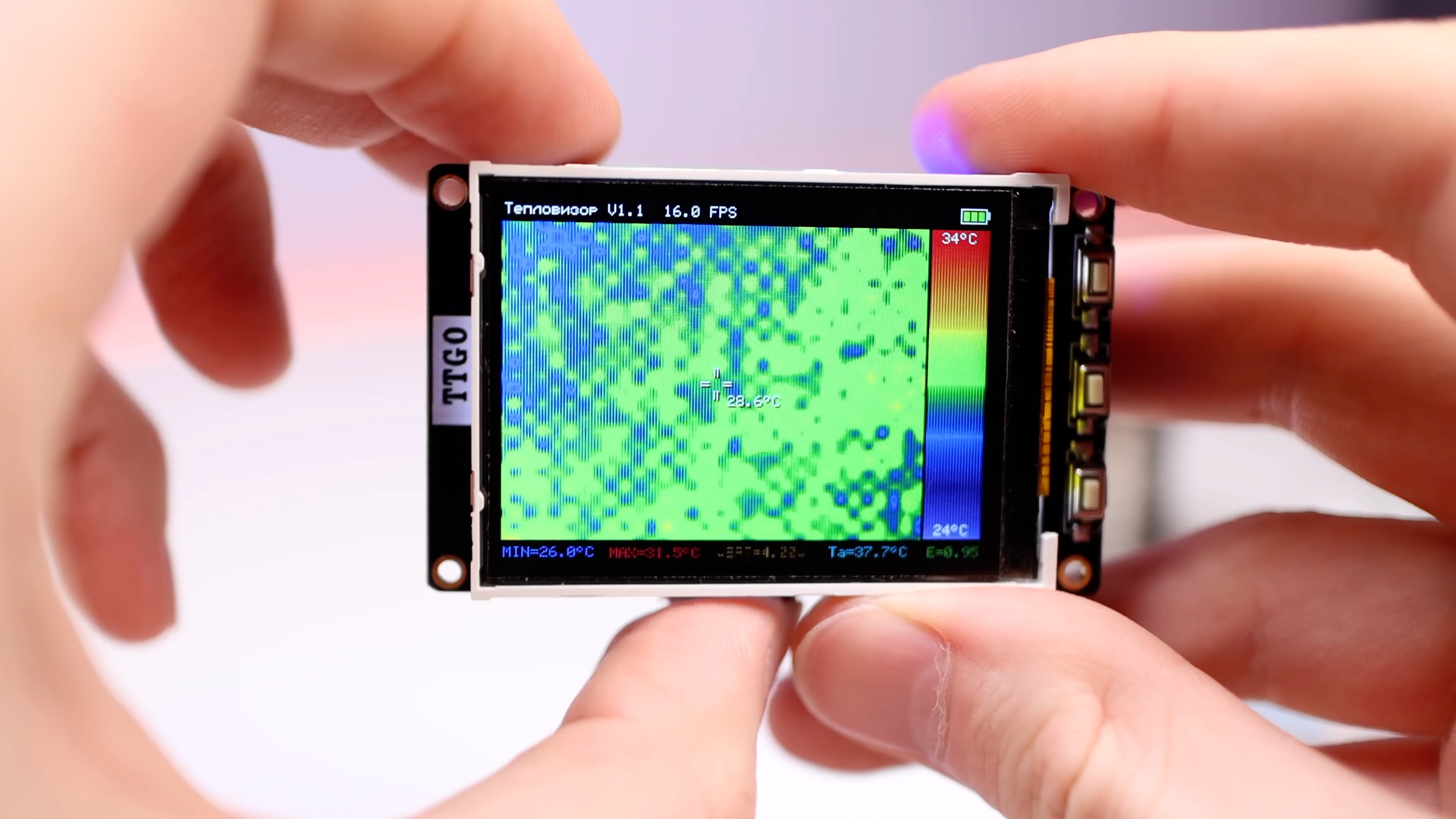
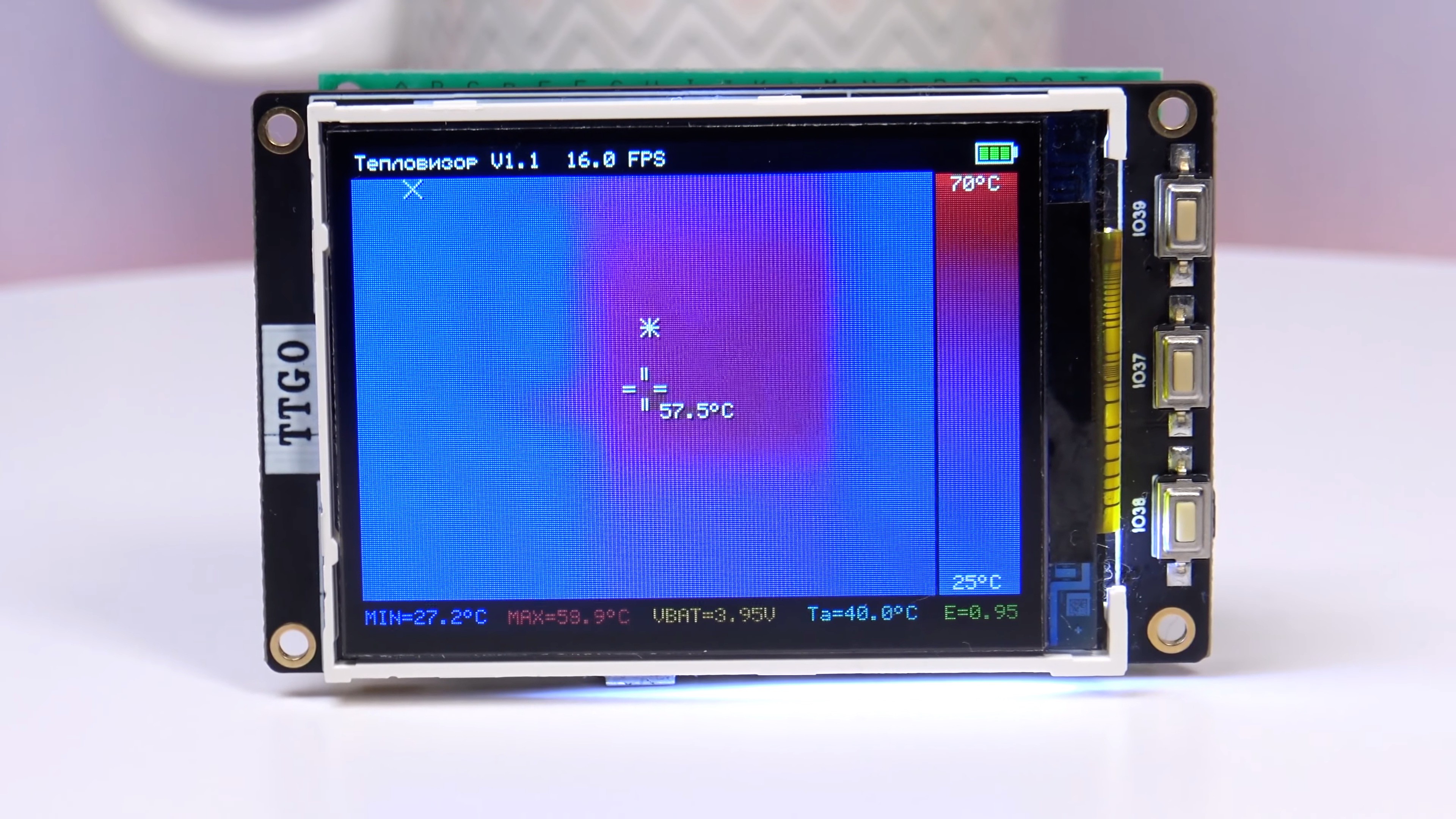
A title is displayed at the top of the screen. To the right, the frequency of data collection and the battery charge is displayed.
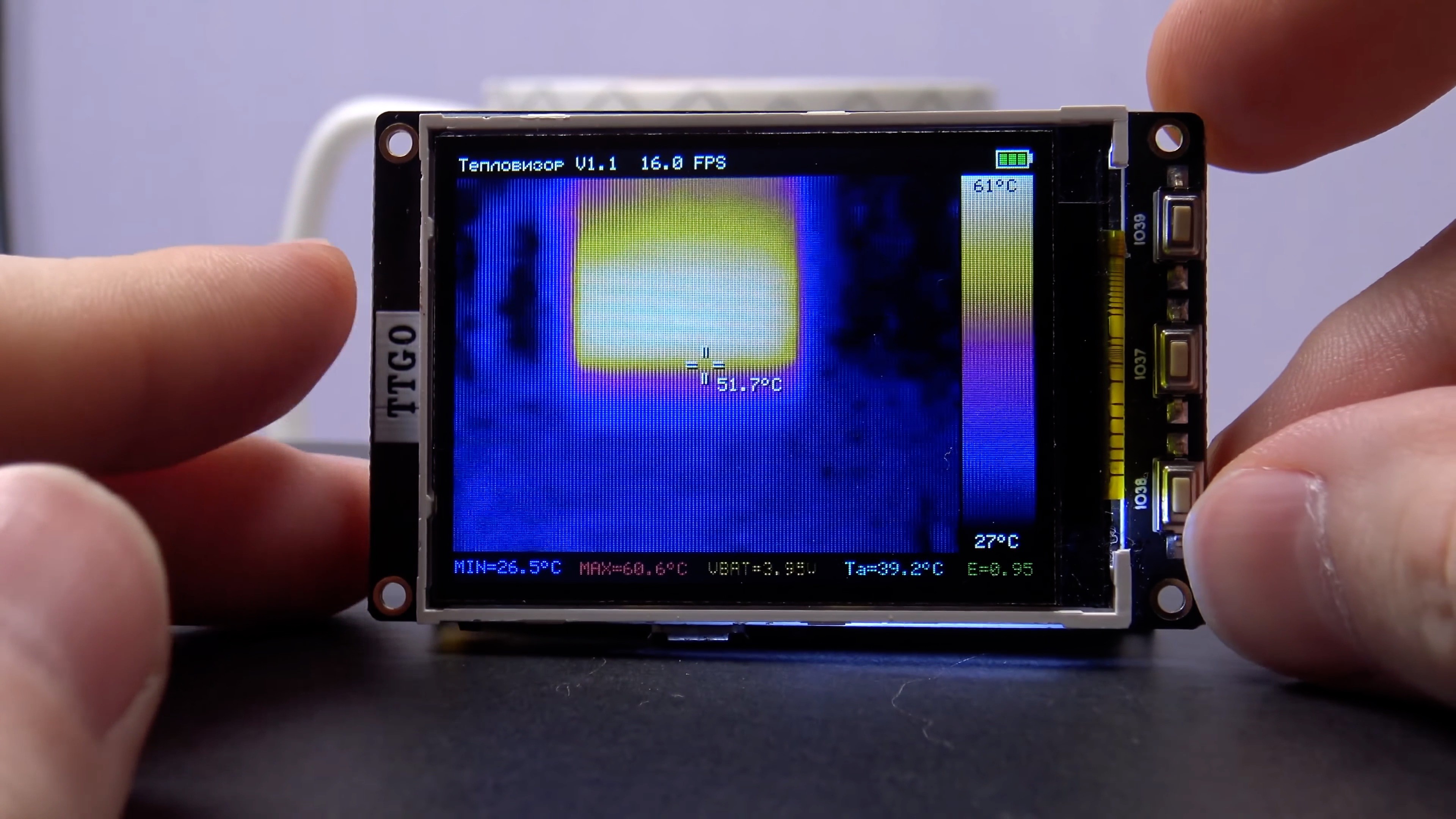
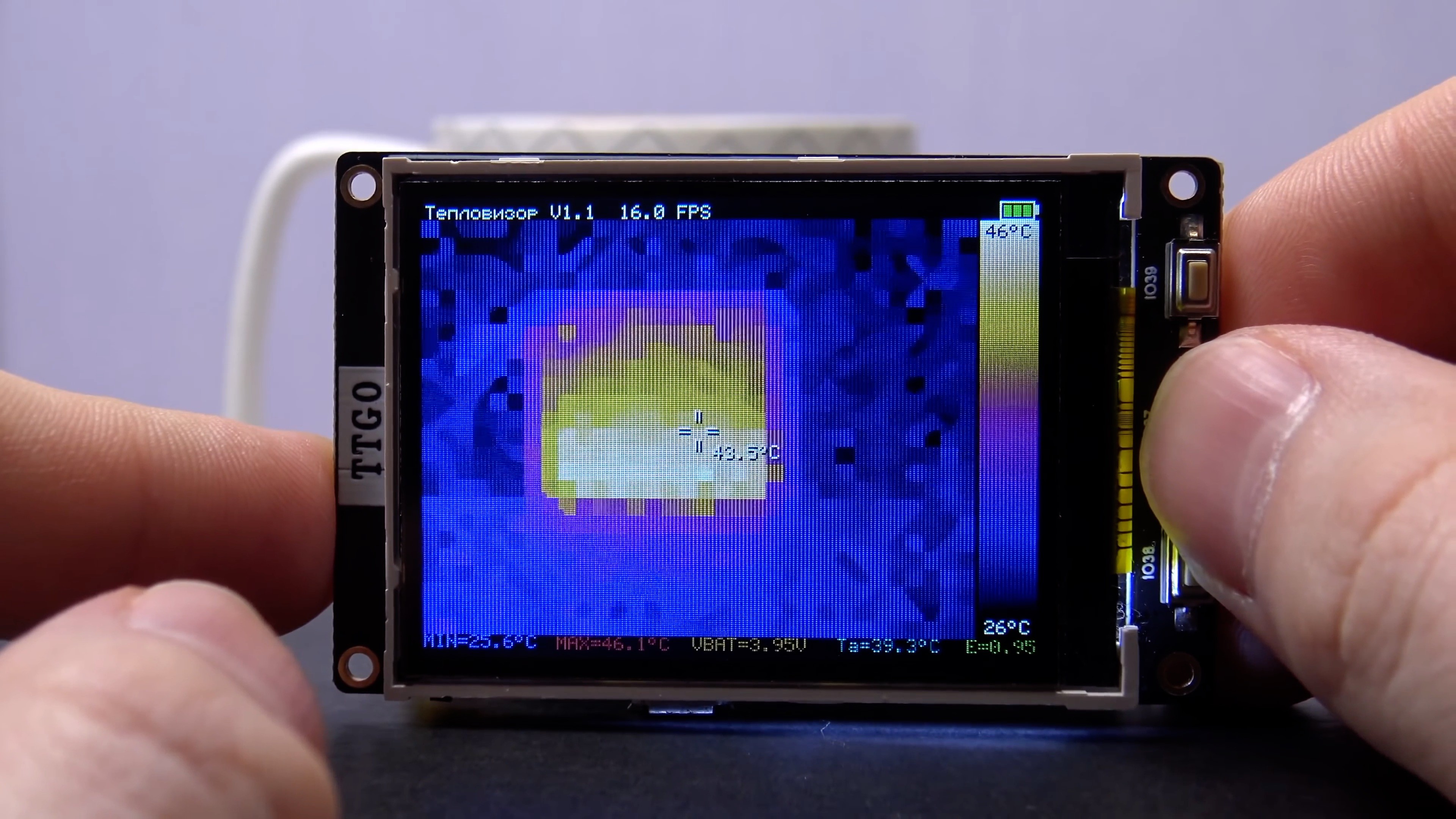
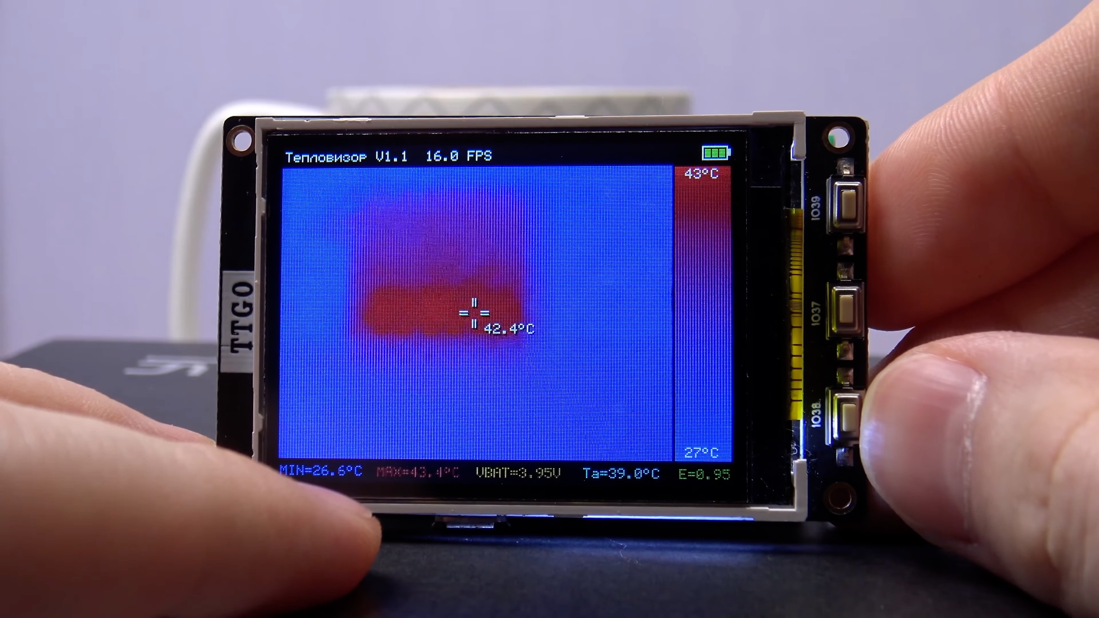
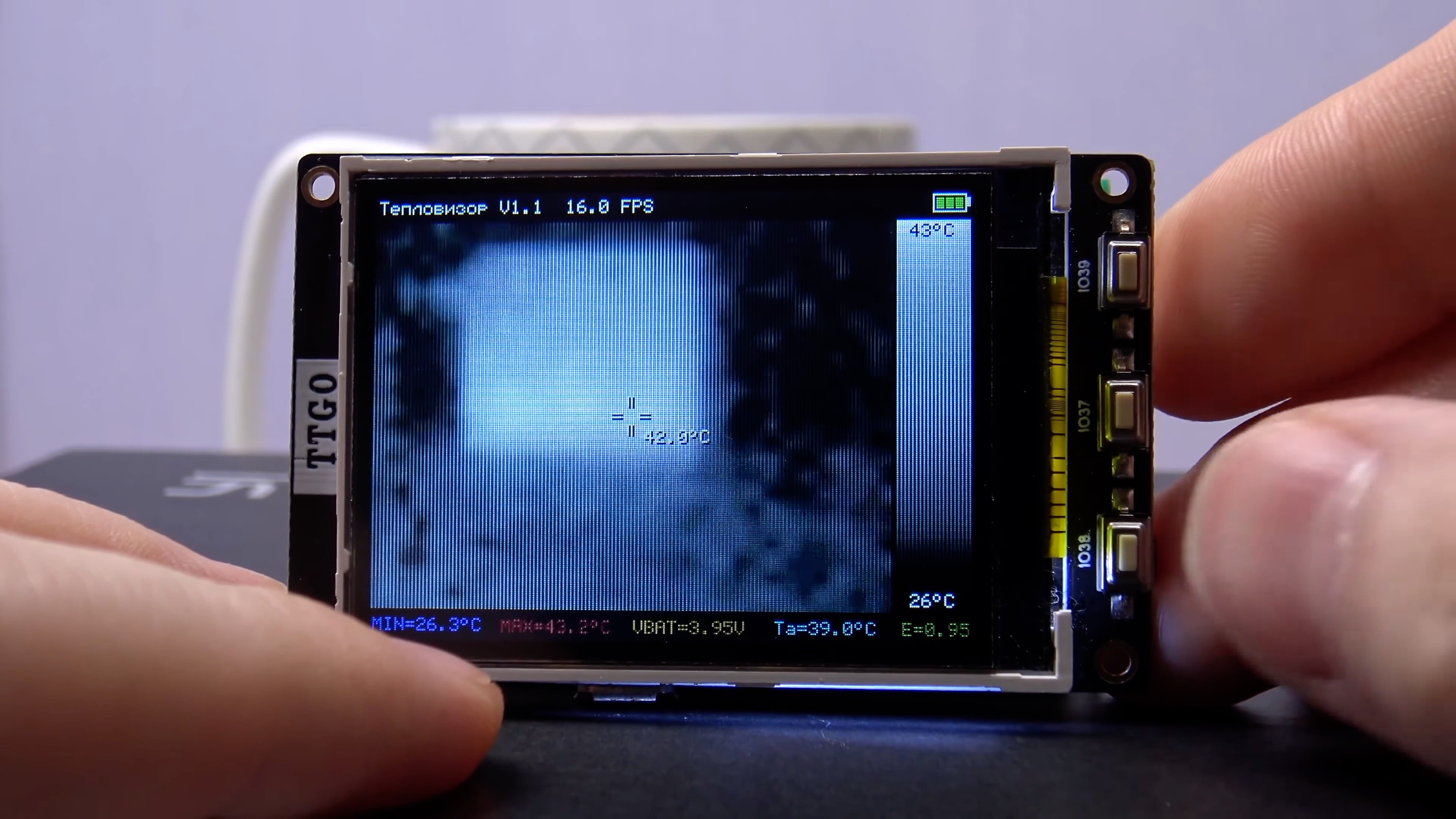
Below is the thermogram output field, an interpreted image from the sensor is displayed on it (an additional 8 points are calculated between 2 points of the image from the sensor). In the middle of the thermogram, I drew a small sight and temperature value corresponding to the point in the center of this sight. This is convenient when you need to measure the temperature of a particular point in the frame. To the right of the thermogram, the color scale is vertically displayed. It is dynamically adjusted along the temperature range in the frame. The minimum and maximum temperatures of the scale are displayed on the scale.
The algorithm for choosing the scale range is arranged so that the range of the scale temperature is always 20 degrees or more to prevent the appearance of excessive noise in the thermogram.
As a scale by default, I use the most popular Iron color scales in thermal imagers (the transition from white to black through yellow, purple and dark blue).
The lower line is displayed:
- minimum temperature in the frame
- maximum temperature in the frame
- voltage on the battery
- MLX90640 temperature, measured by itself. MLX90640 measures its temperature because it is needed to calculate the temperature in the thermogram
- MLX90640 power supply (read from the sensor)
3 buttons to the right of the display in the firmware are not yet involved, but I will soon use them in the firmware 1.1.
Another small addition regarding the filtering of the sensor power.
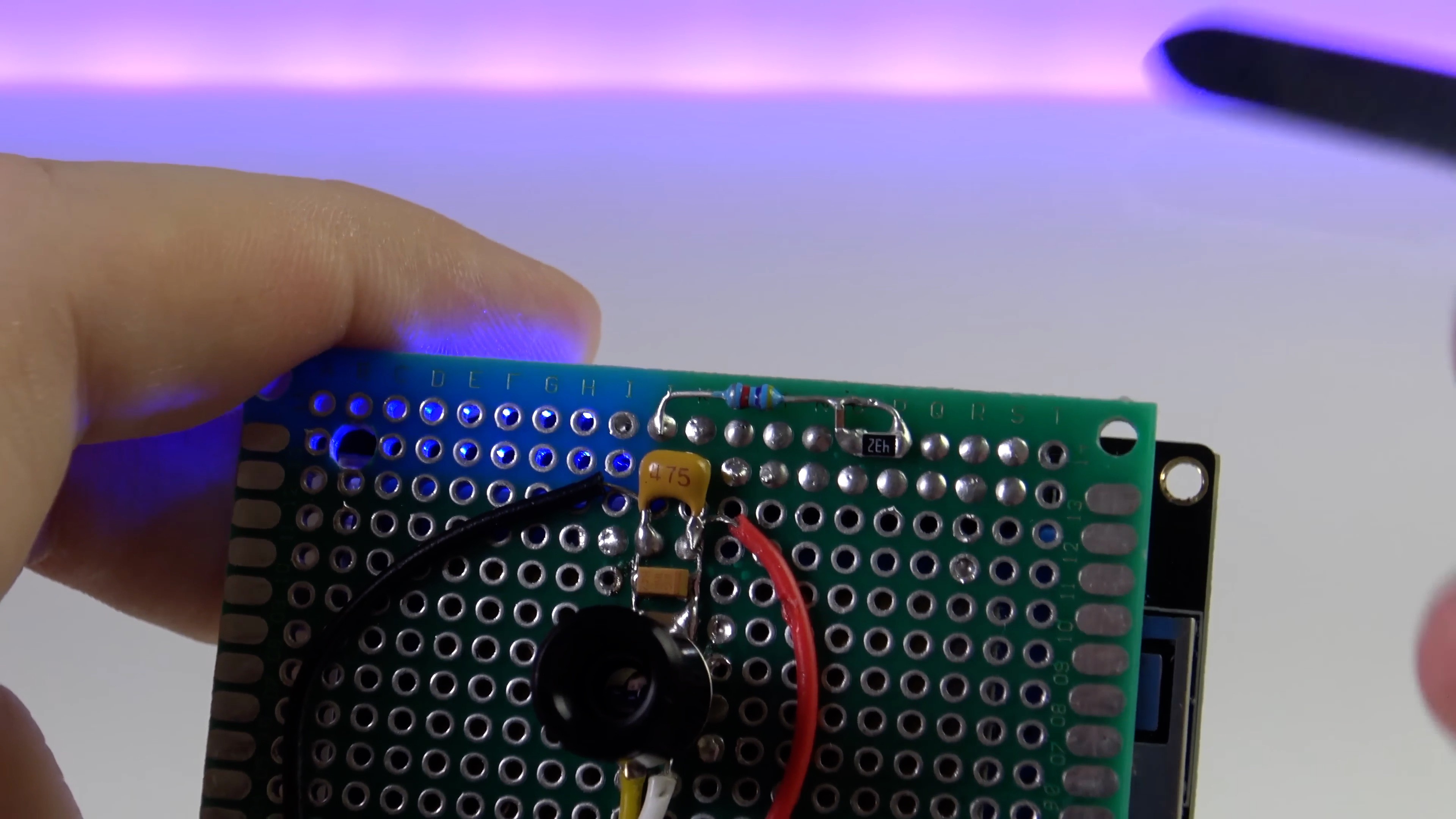
As you can see, I use 3 capacitors. Capacitors 0.1 μF and 1 μF are described in the documentation for the sensor. At first I did not have them and vertical strips were visible in the thermogram.
With these 2 capacitors it became better, but it became much better after adding the third capacitor 4.7 μF.

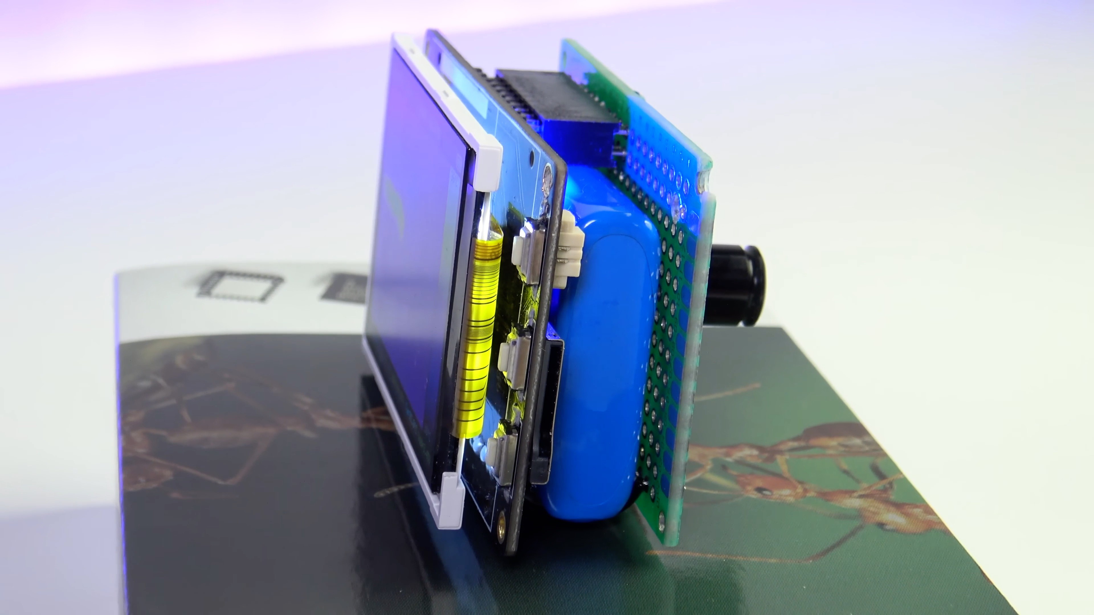
Hardware V1.1
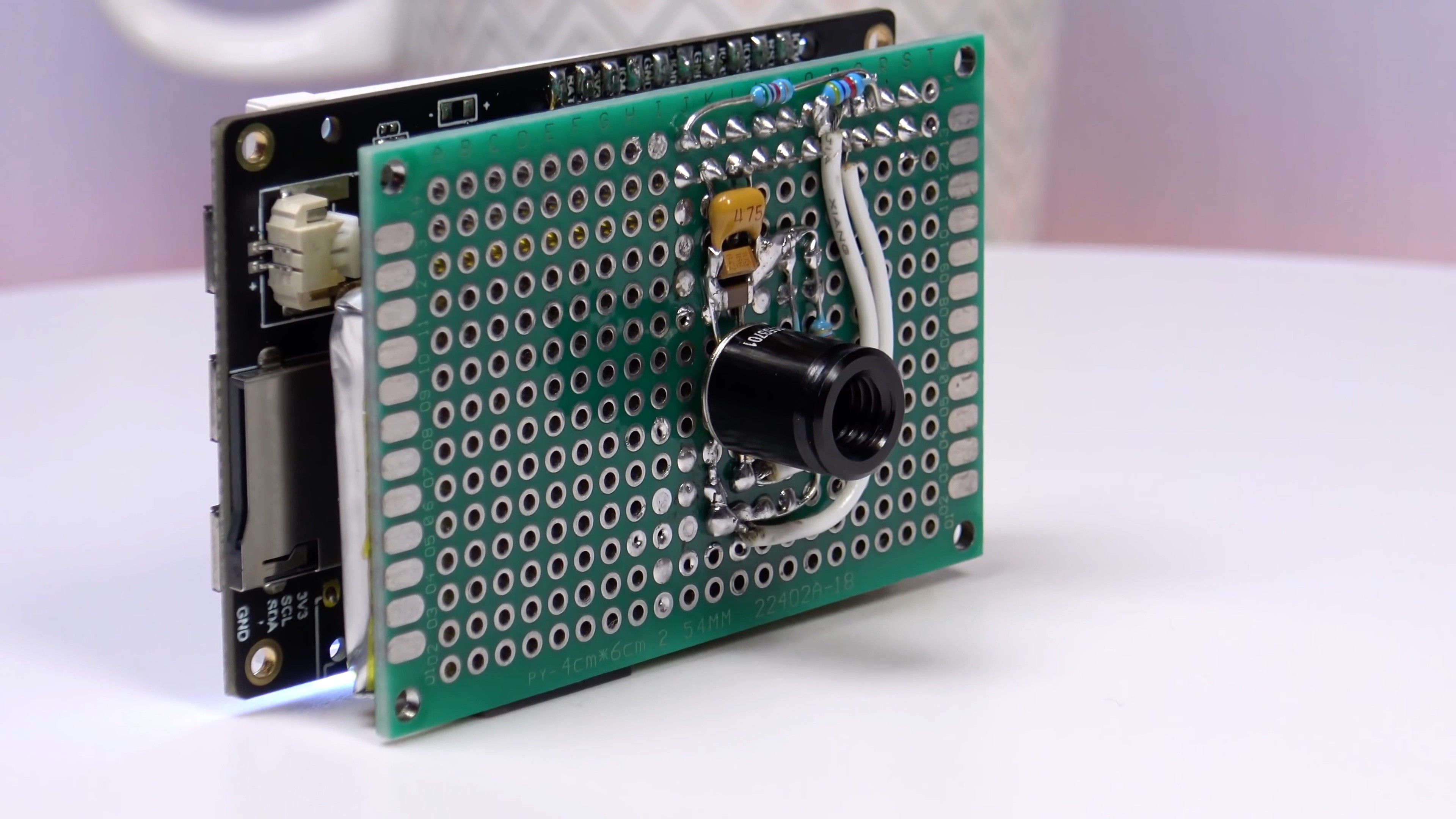
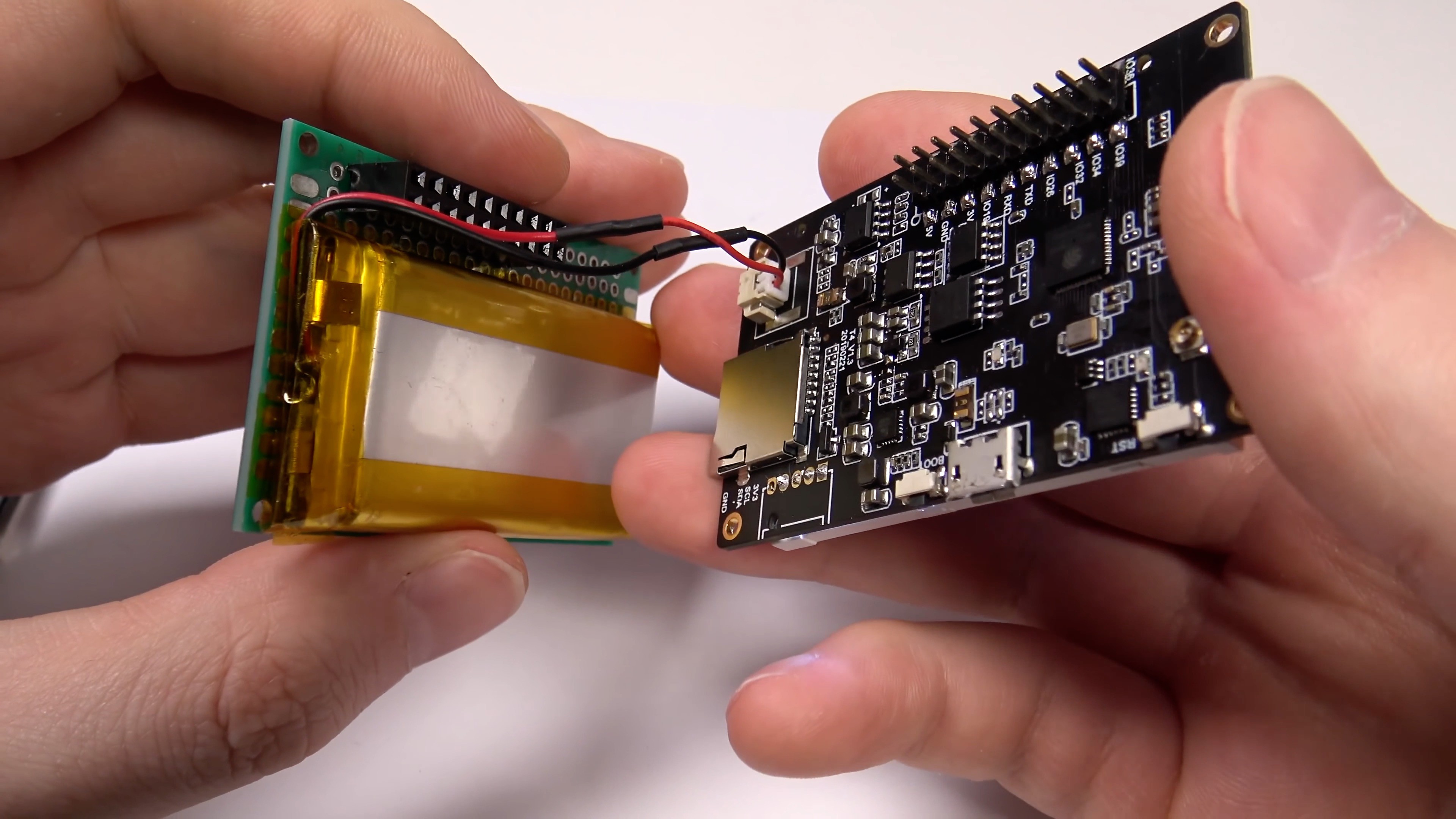
The first thing I changed was the battery.
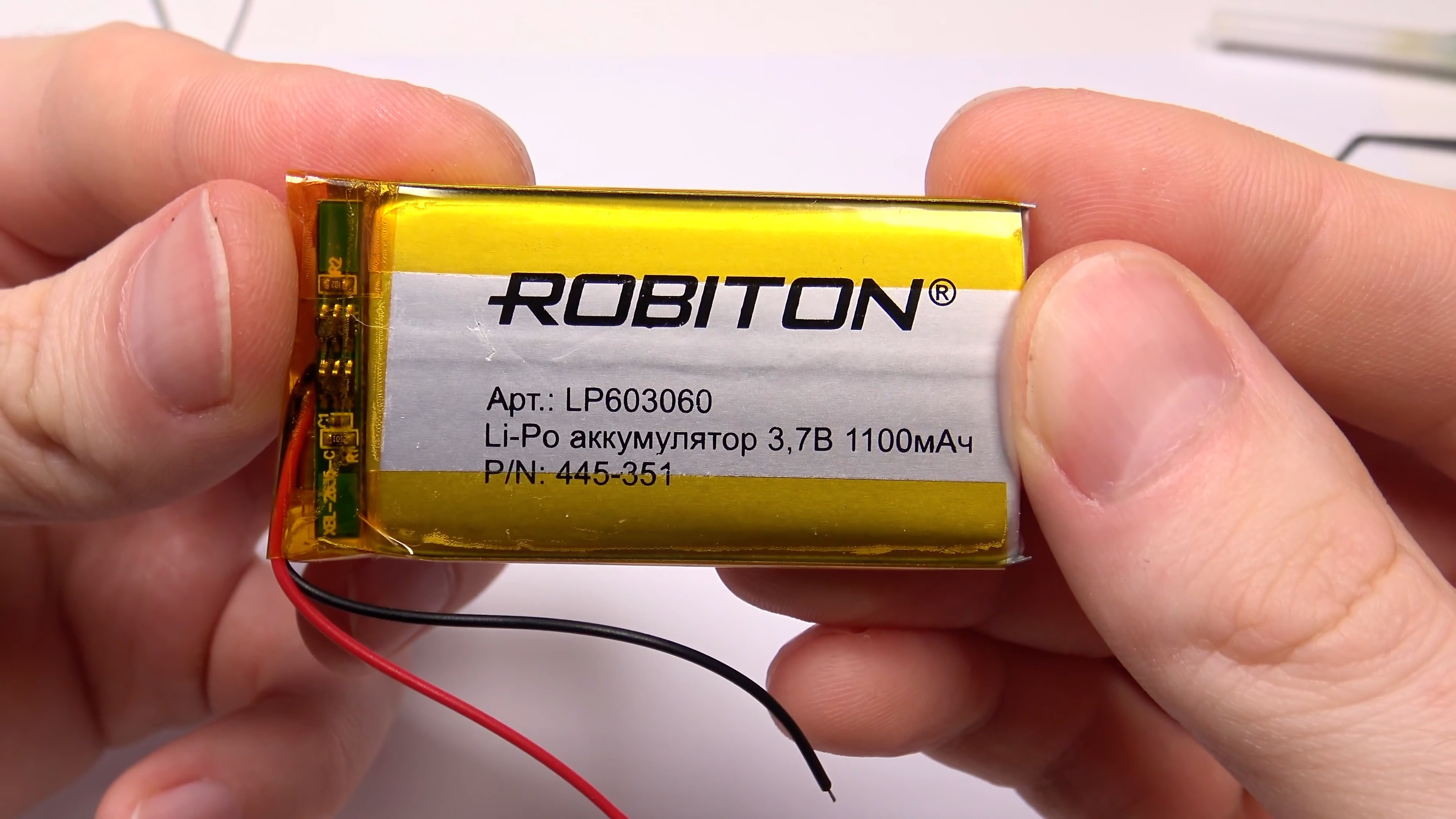
This is a Robiton LP603060 with a capacity of 1100 mA. As you can see, the capacity is smaller and this is perhaps the only minor update. But it is necessary, because with a large version 1.0 battery, when assembling the thermal imager, the 20-pin connector was not fully inserted and the thermal imager boards were not parallel. This would prevent me from making a high-quality design of the device and making a good case for it. I could probably use a slightly thicker battery, but this is the only suitable option that I could find in my local electronics store.
Now the battery life of the thermal imager from a charged battery is 3 hours and 42 minutes, which is also quite good.
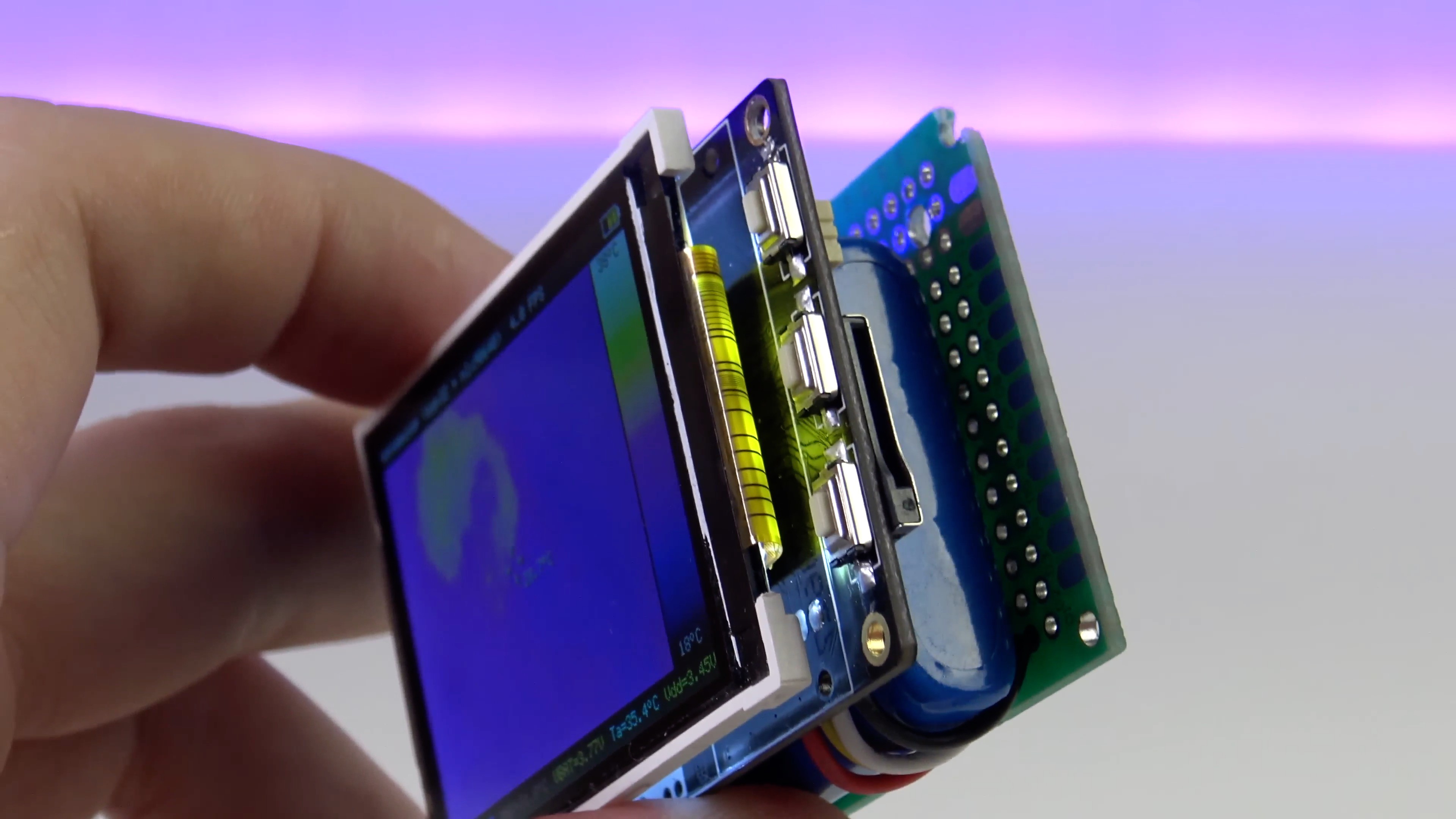
I also got rid of connecting 4 wires without a connector to the pins of the GROVE connector. The fact is that the ESP32 has an interesting feature - the ability to programmatically switch the internal lines of hardware interfaces to almost any external pins of the ESP32. This allowed me to bring the i2c interface to the free pins of the 2x10 connector.
This made it necessary to place 2 i2c bus pull-up resistors on the back board.
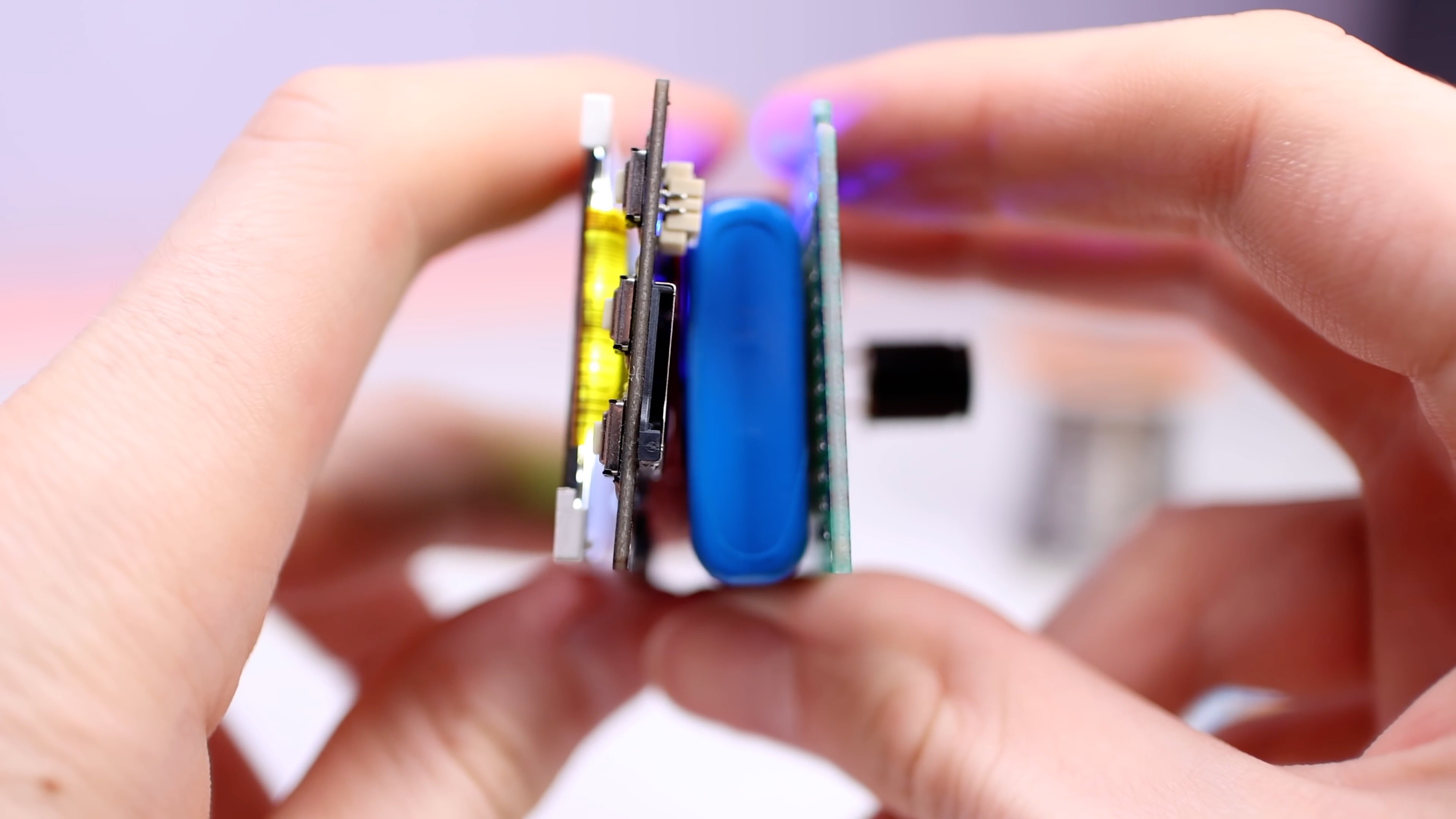
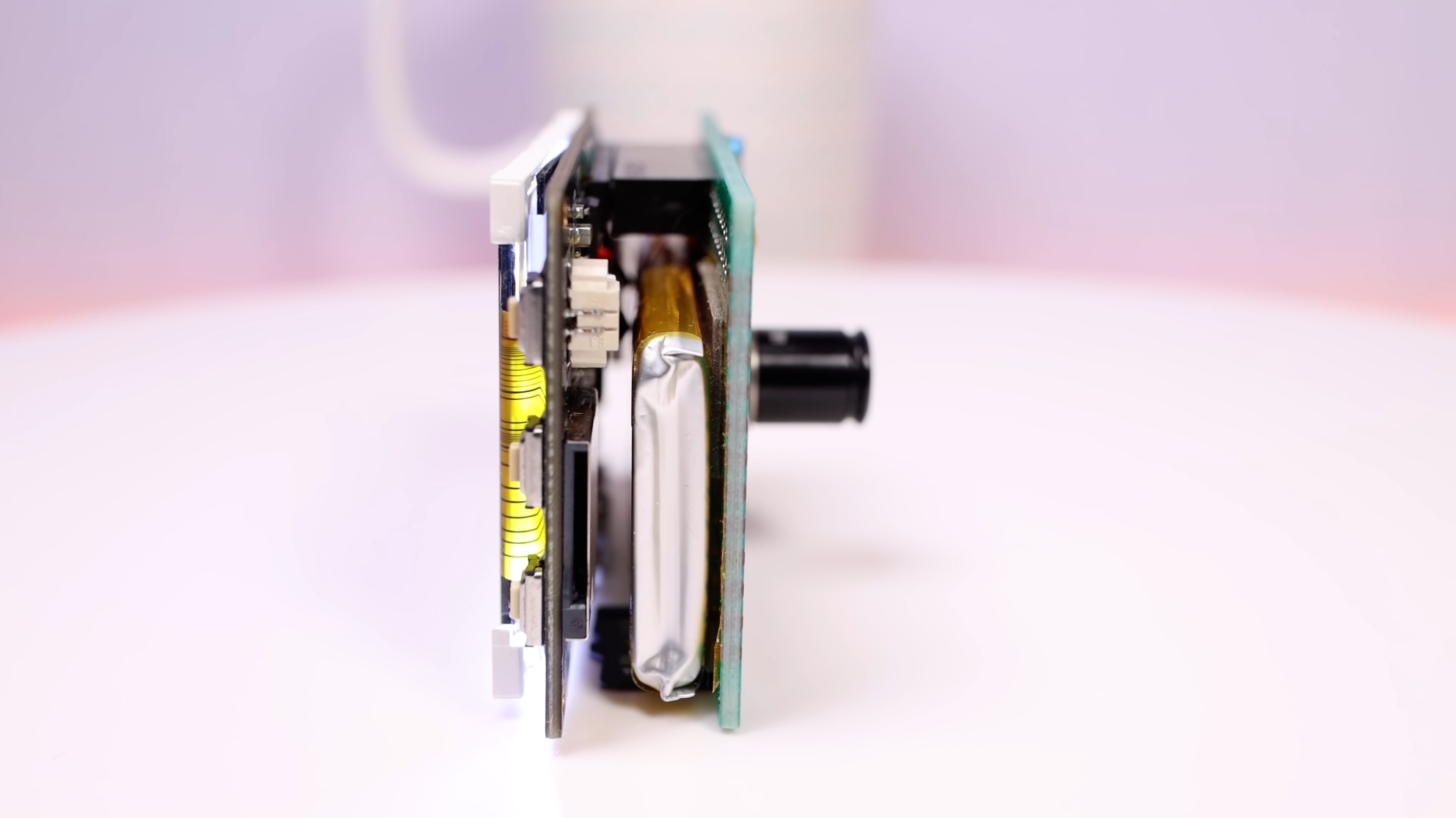
Now there is only 1 connector between the thermal imager boards (+ a connector for connecting the battery to the TTGO T4 board), very convenient!
In the new hardware version of the device, I used a new revision of the TTGO T4 board (1.3).
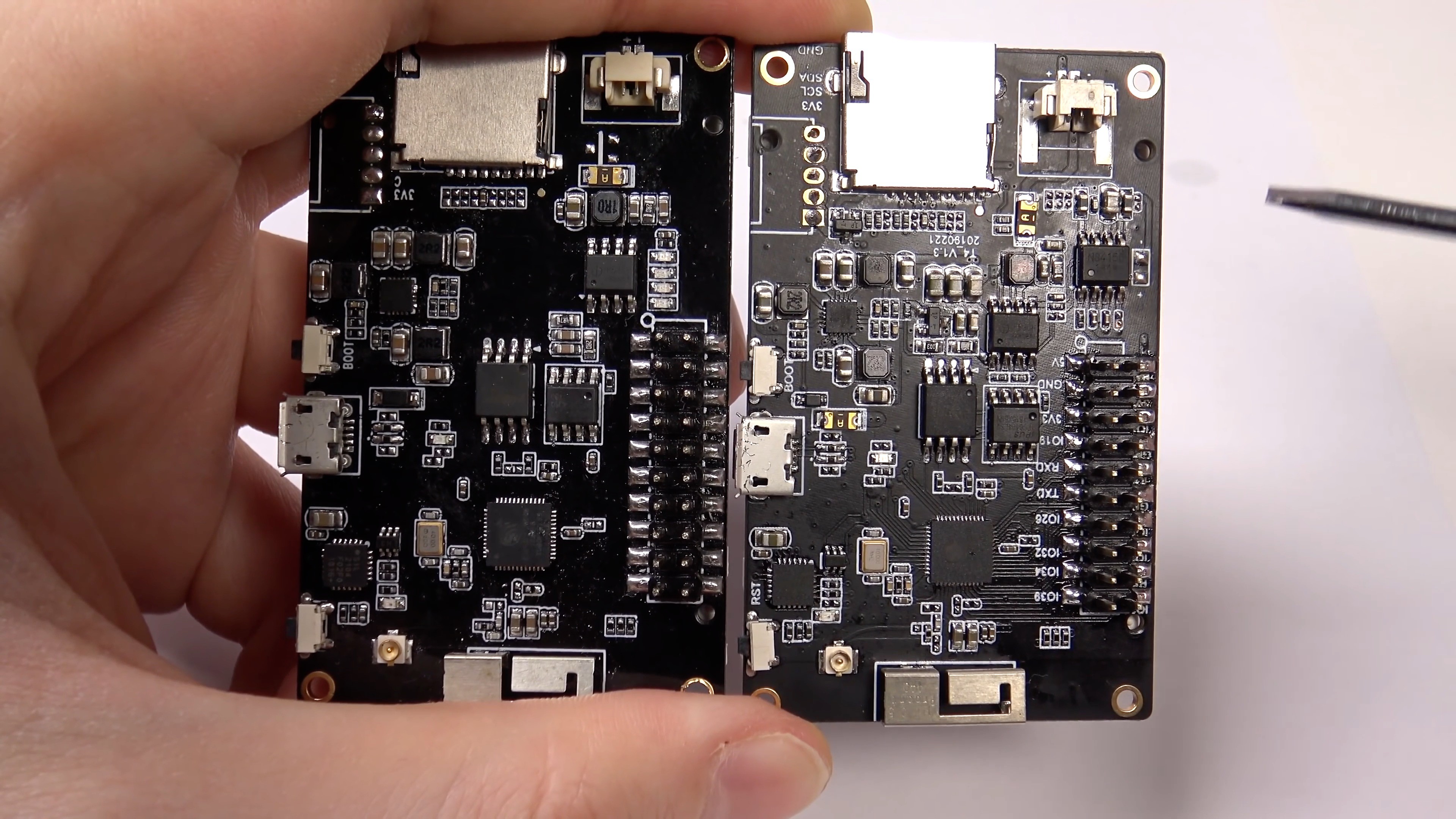
Changes:
- A 3 W class D amplifier based on the NSIWAY NS4150 chip has been added to the board.
- The battery charge indicators have been removed, and the power bank controller has been replaced with a version with an i2c interface. Unfortunately, at the time of debugging the firmware, I did not yet have documentation for the protocol, so I do not yet use the ability to read the charging status via i2c.
- The connection of the display to the ESP32 has changed. You can switch the display connection to boards of different revisions using constants in the firmware 1.1 sources.
- Now you can control the brightness of the display backlight using PWM. Now in firmware 1.1, you can adjust the brightness of the display backlight in the settings menu of the thermal imager.
Firmware 1.1
Once on a long weekend, I decided to make firmware improvements that I planned to do a long time ago. As a result, I got so carried away that I did a lot more, this is a really big upgrade from version 1.0.
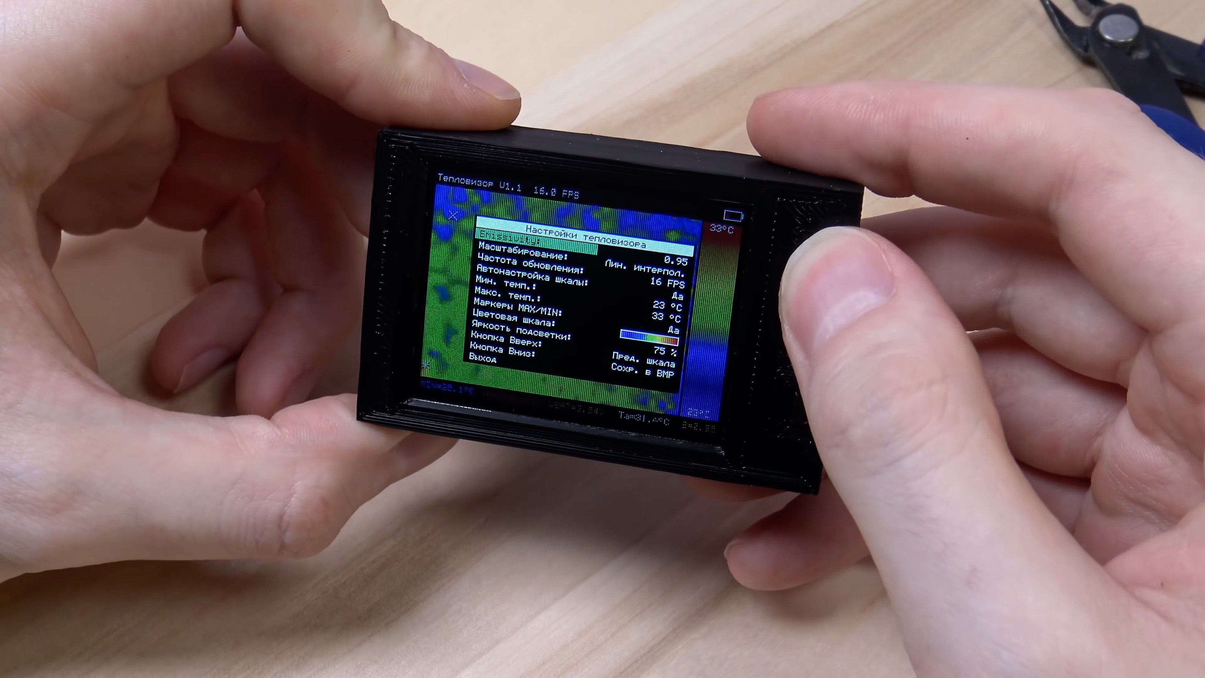
The thermal imager now has a setup menu. To open menu, press the middle button on the front of the device. The same button is used to confirm actions in this menu.
Top and bottom buttons are used to navigate the menu up/down, and in idle mode these buttons call up quick actions that can be reassigned through the menu! For example, you can assign these buttons to adjust the brightness of the display or to save current frame to a microSD flash drive.
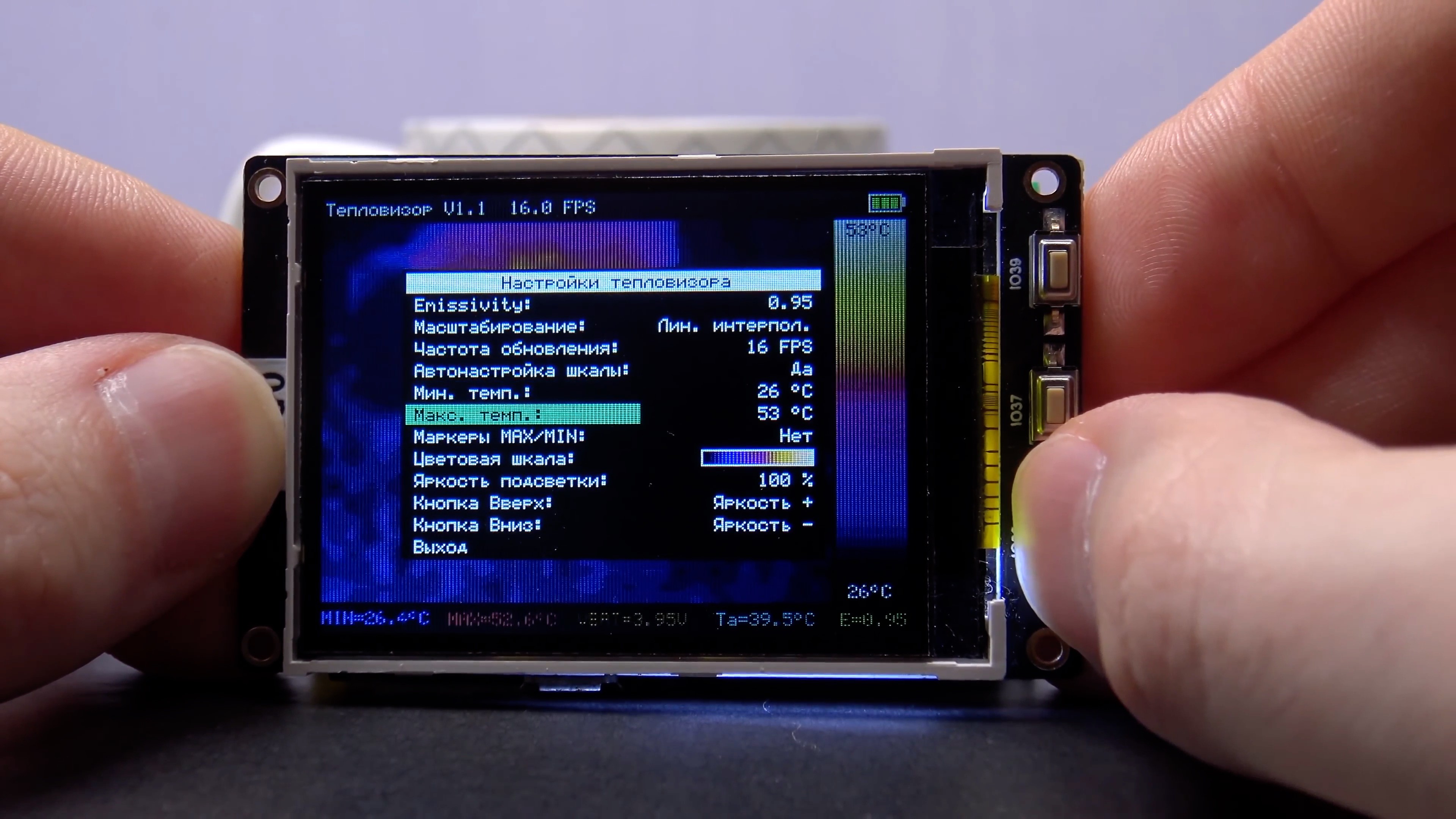
The menu is very simple, one-level. Here you can:
- Set emissivity (the more shiny the surface of the object, the less emissivity)
- Select the scaling method
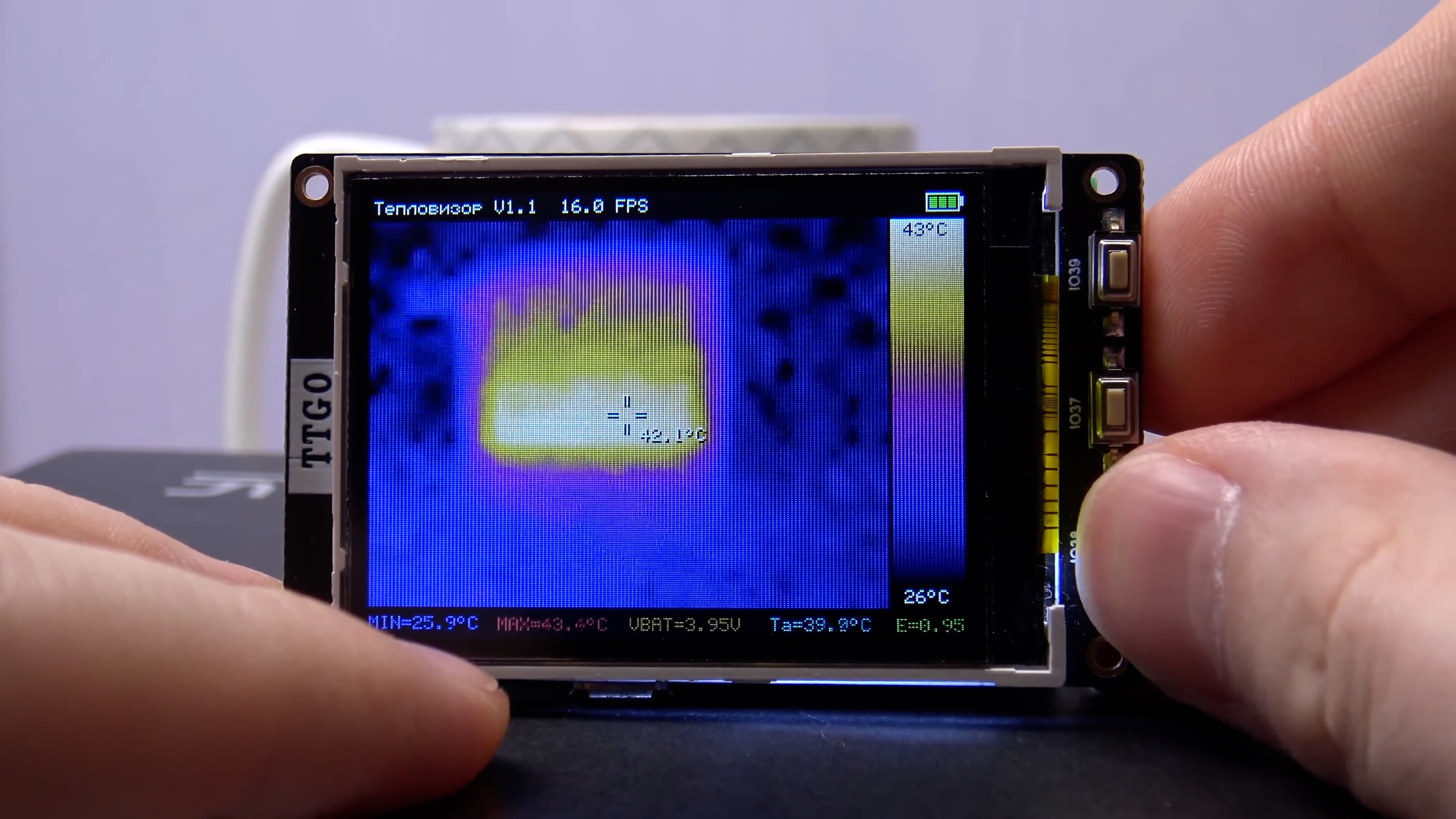
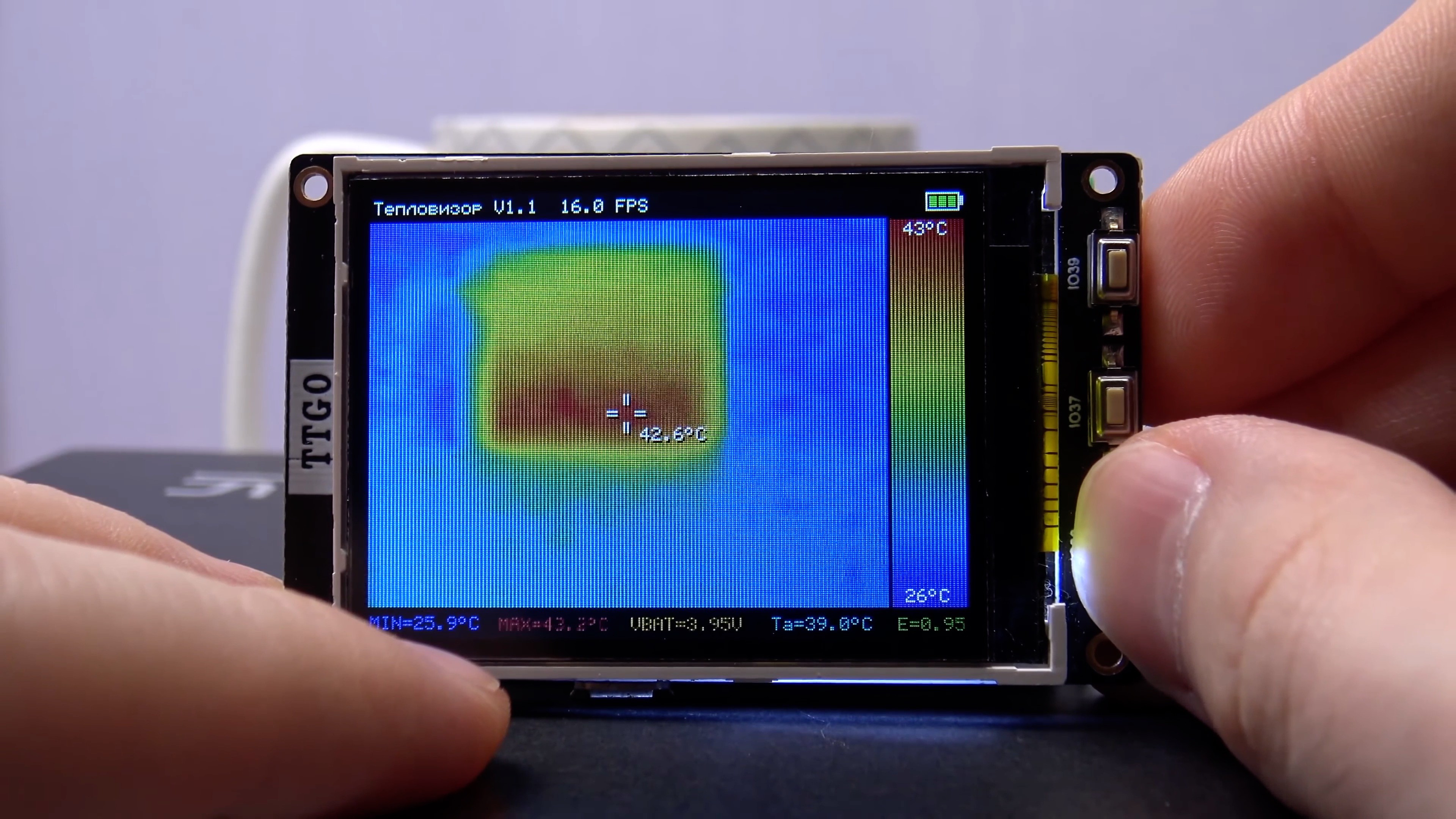
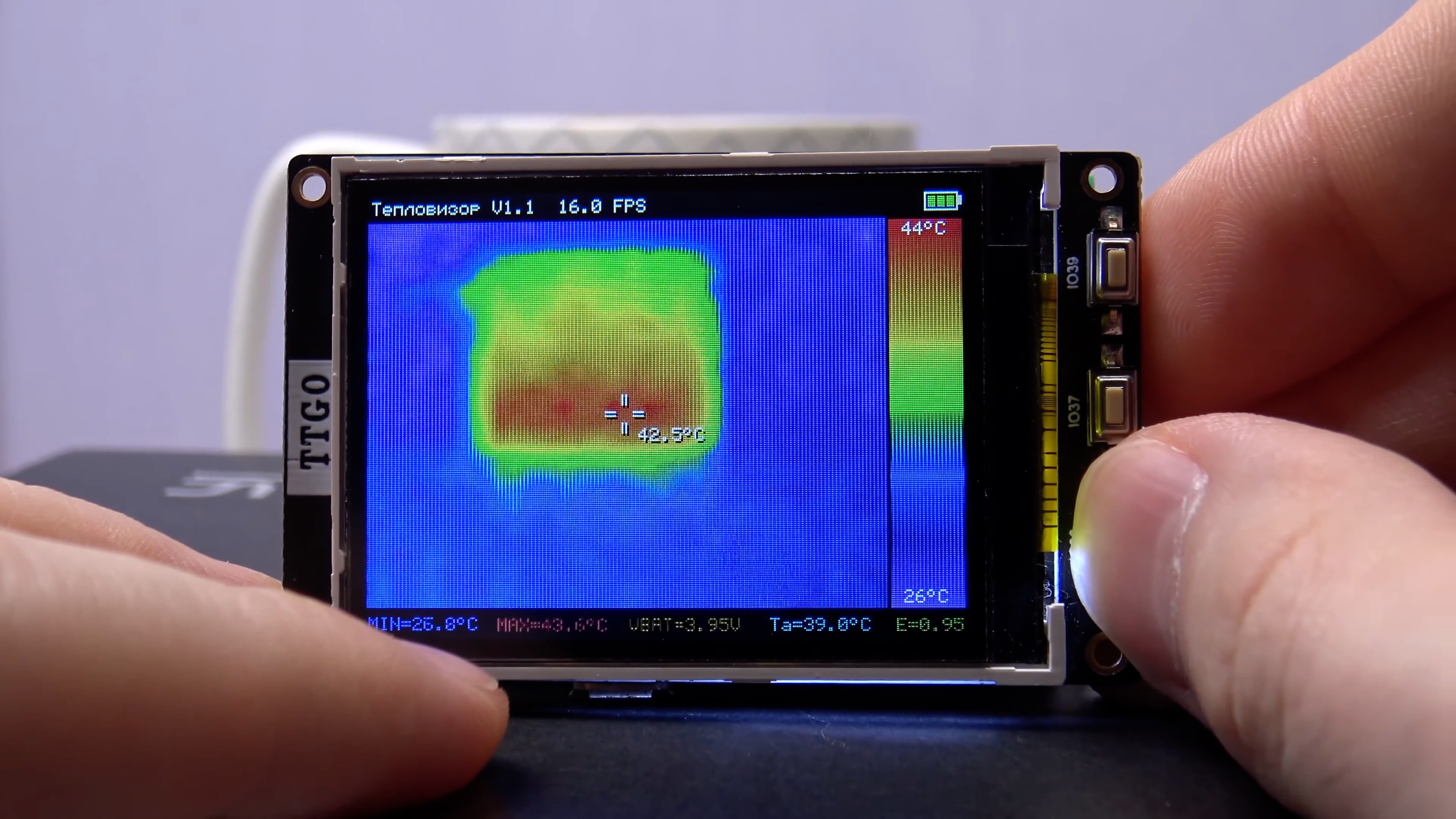
Linear interpolation:
Nearest:
HQ3X 2x algorithm:
- Select thermogram update frequency
- Enable/disable auto-tuning of the color scale range
- Set upper and lower limits of the color scale (if the auto-adjustment of the scale is disabled)
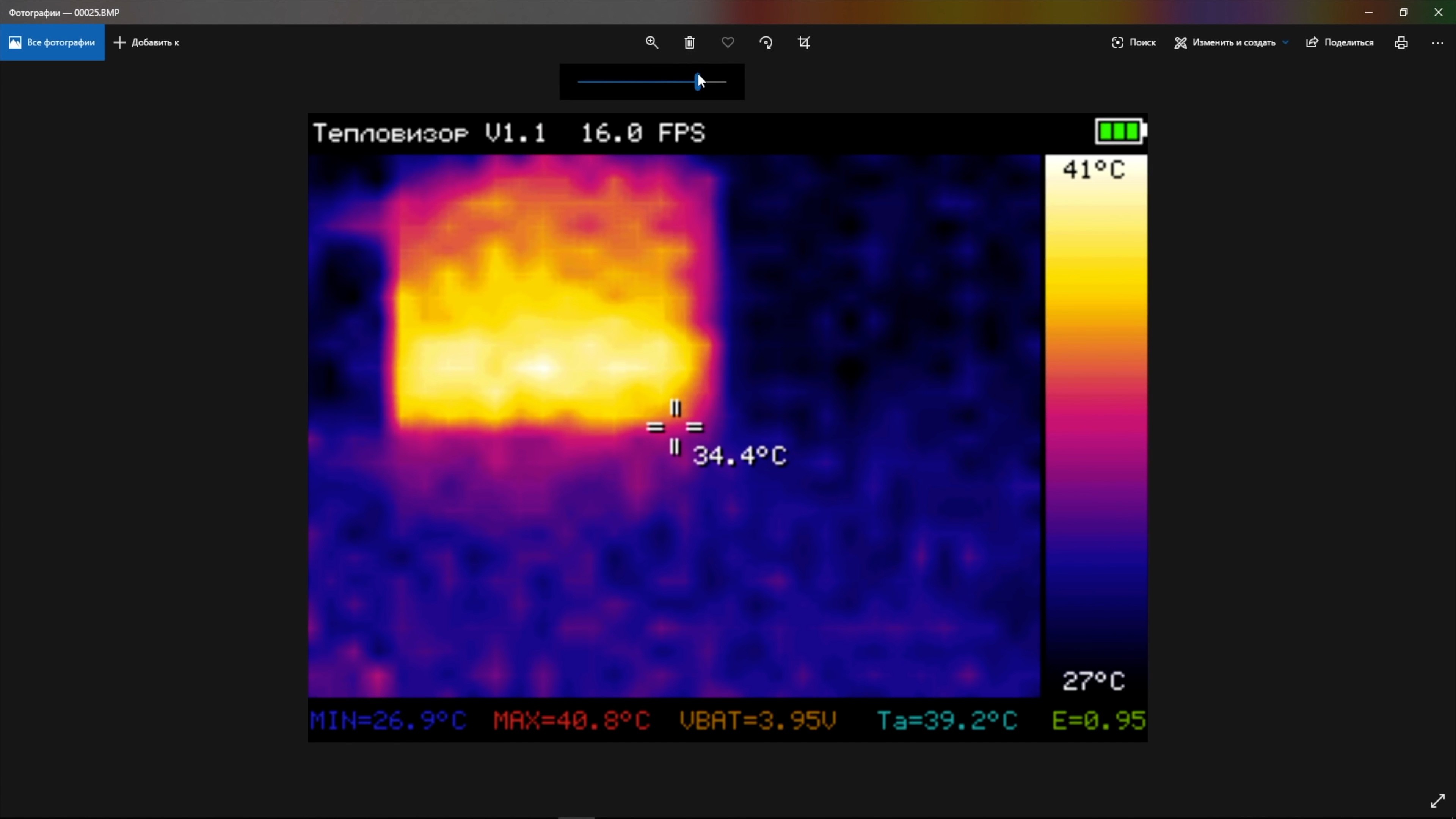
- Enable/disable the minimum and maximum temperature markers in the frame. An asterisk indicates the maximum temperature, and a cross indicates the minimum. The temperature values corresponding to these markers are displayed at the bottom in the status line.
- Select the type of color scale
IRON color scale:
Smooth rainbow color scale:
Contrast rainbow color scale:
Blue-red color scale:
Black-and-white color scale:
- Set backlight brightness (in 5% increments)
- Select 2 functions for up and down buttons (save thermogram to a CSV file on microSD / save thermogram to a BMP file on microSD / turn markers on/off / next scale / previous scale / increase emissivity / decrease emissivity / increase backlight brightness / decrease backlight brightness).
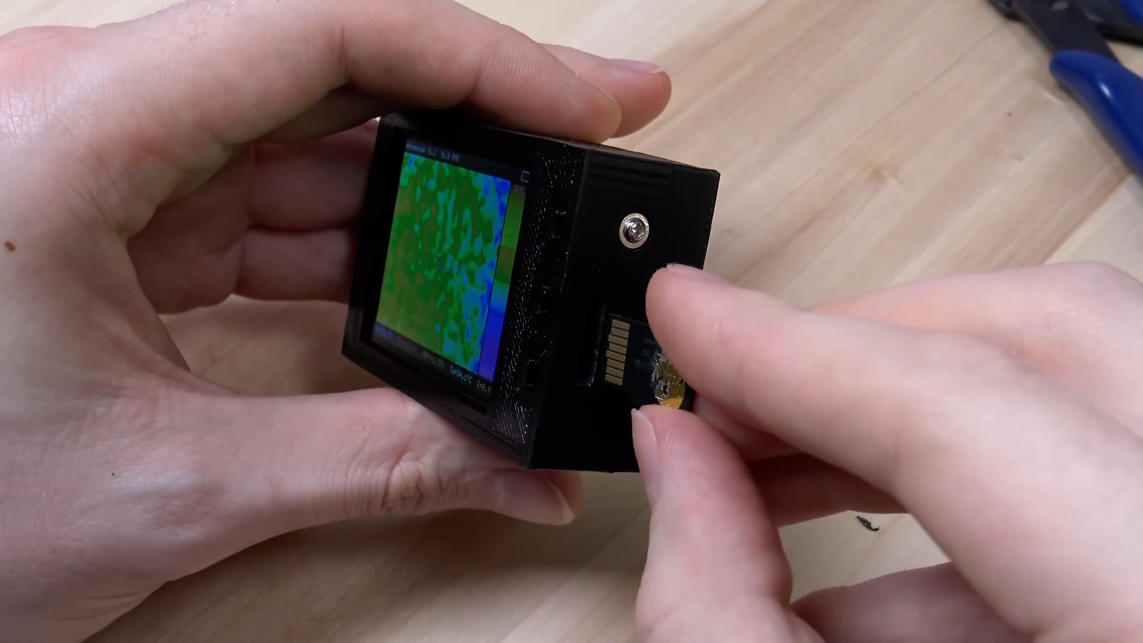
To save thermograms to a microSD flash card, you need to assign this function to the up or down button.
If the flash drive is not connected, an error message is displayed.
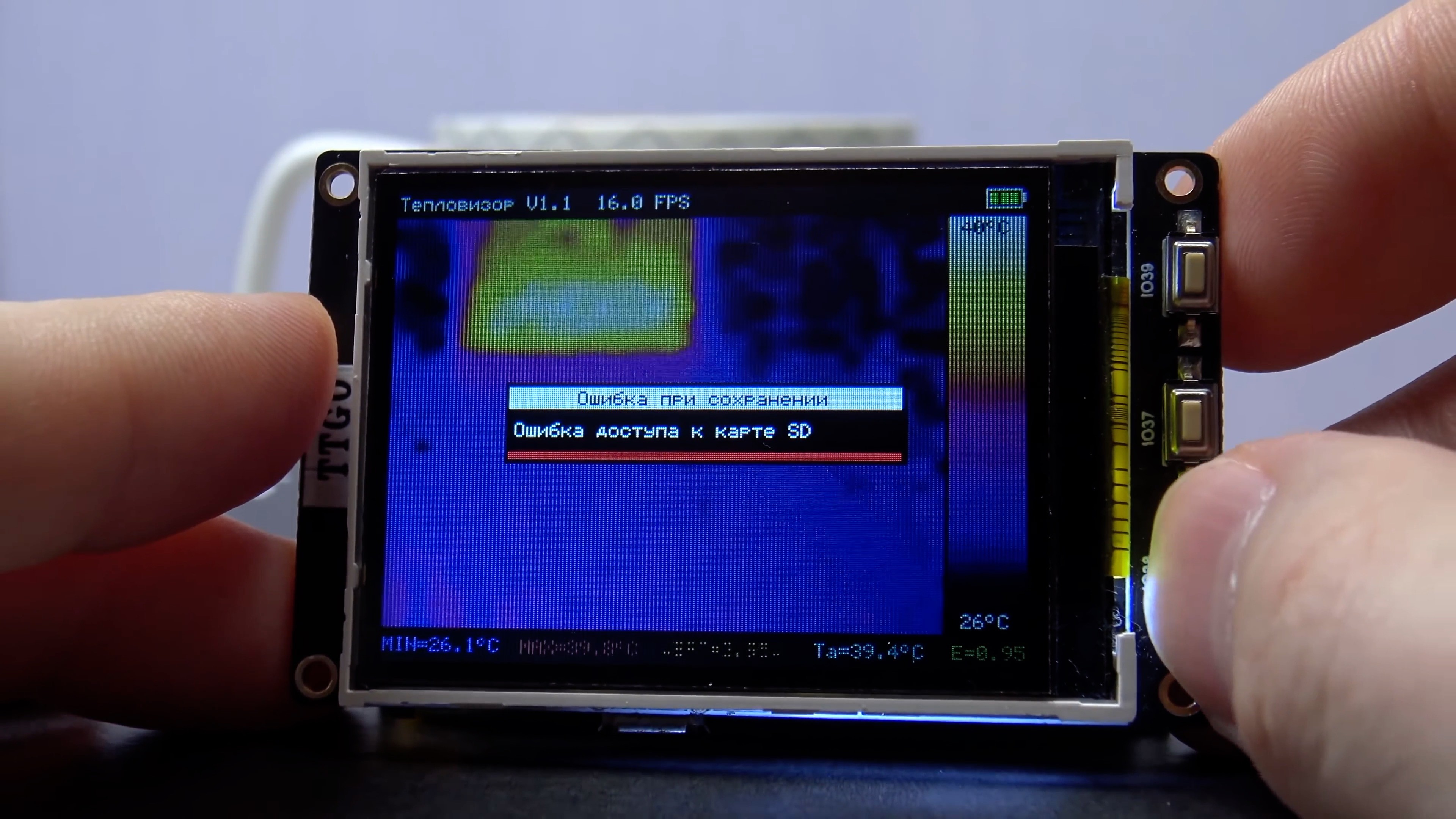
The microSD flash card can be connected at any time, rebooting the thermal imager after that is not required.
If the microSD flash card is connected, then an indicator of the thermogram saving process appears on the screen.
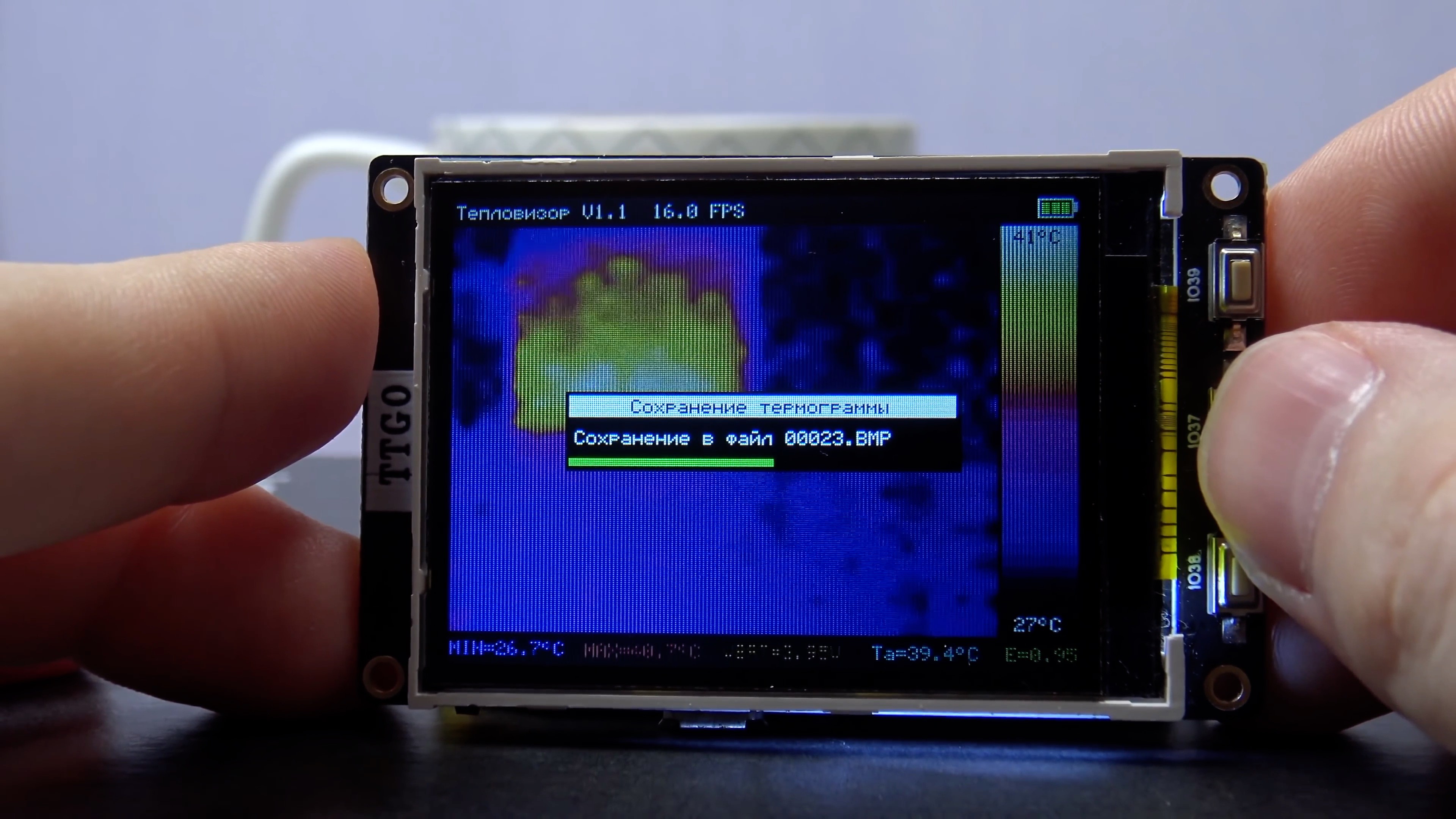
After the operation is completed, a message about the successful saving of the file is displayed on the screen.
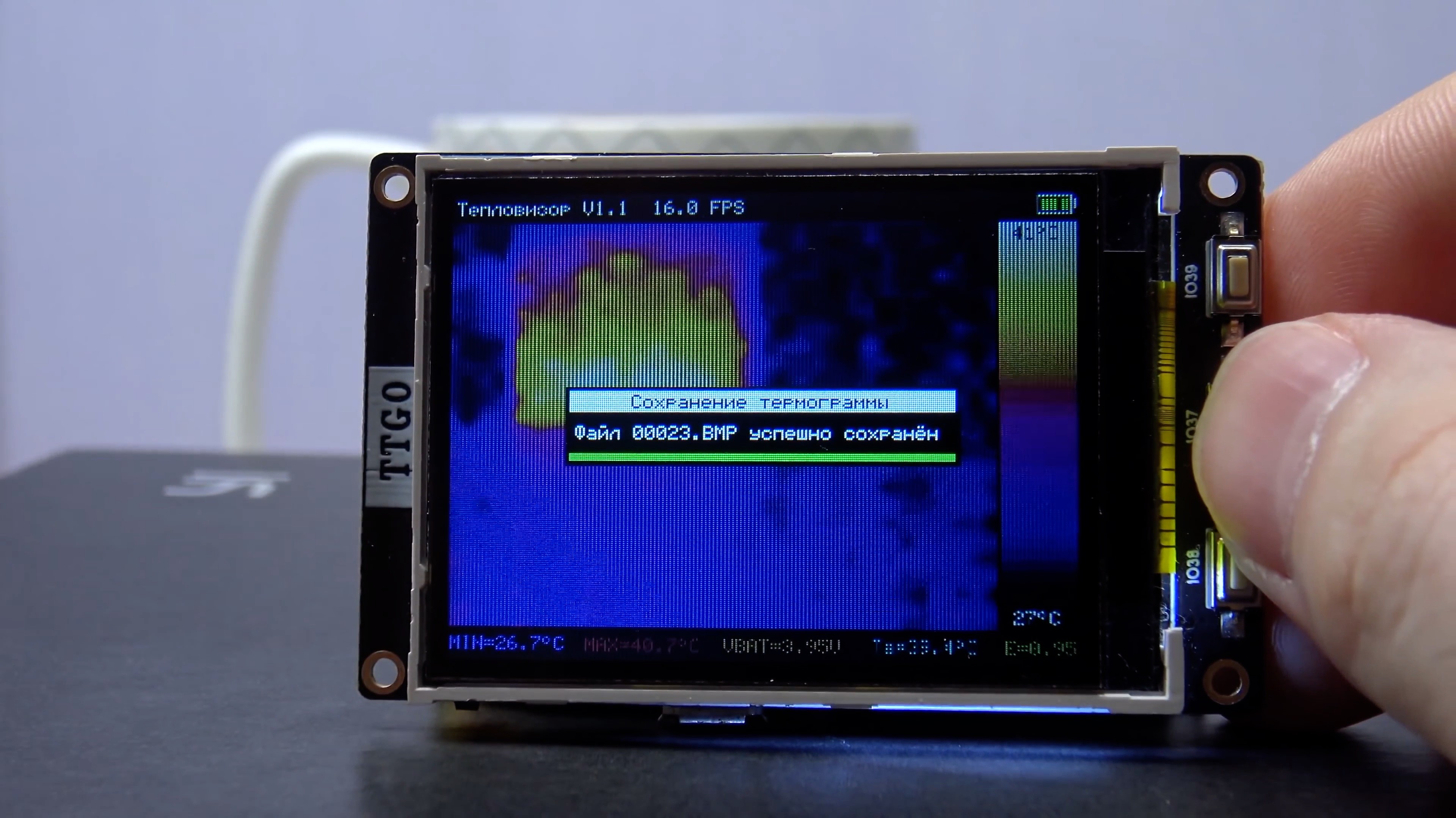
When saving to a BMP file, a full screenshot of the thermal imager interface is saved (with a scale and values in the status line).
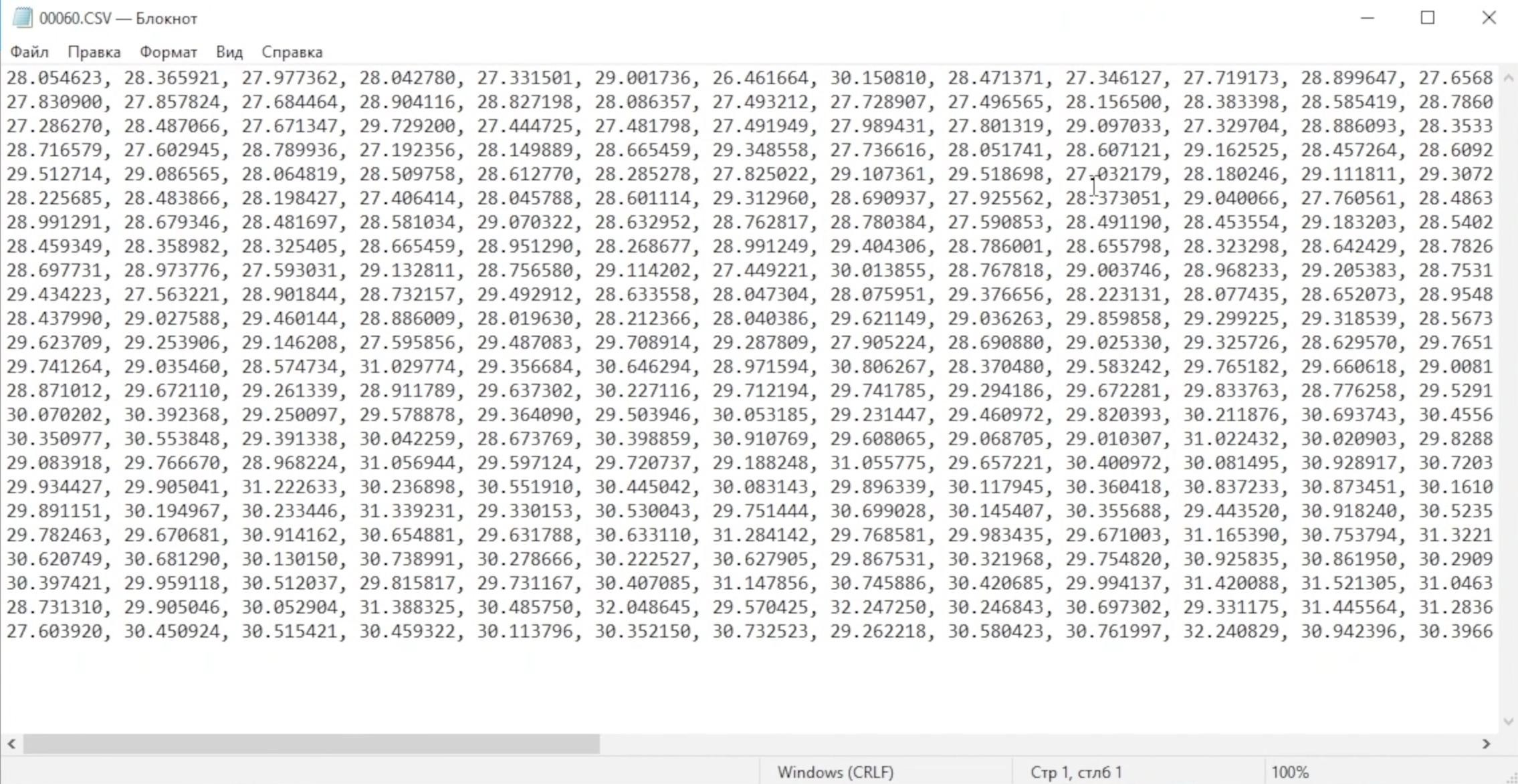
When saving to a CSV file, 32x24 temperatures are saved as real numbers. This data can be loaded into common mathematical modeling programs or into your own programs.
There is no special eject procedure to remove the microSD card. The flash drive can be removed at any time, but not in the process of saving a file to it. If the flash drive is removed while the file is being saved, the file system on the flash drive may be damaged.
Some interesting features inside firmware v1.1:
- The work of reading data from the sensor and calculating the thermogram is given to the second core of the microcontroller (I remind you that the ESP32 is a dual-core microcontroller). This made it possible to parallelize the preparation of the thermogram and the output of the visual interface. As a result, I decided to increase the default thermogram refresh rate from 4 Hz to 16 Hz. This works pretty well.
- The task of generating events from buttons works on the second ESP32 core. For the down and up buttons, long press detection is implemented. This is used to quickly change the value while holding the up/down button. If the up/down button is held down for more than 5 seconds, the rate of change of the value is further accelerated.
- The GUI output task (including thermogram interpolation, button event processing) runs on the first ESP32 core. Also on this core all the initial initialization of the periphery is performed.
- Button click events are sent between tasks using the FreeRTOS queue.
- Disabled the output of many debug messages in the UART (they also slow down the program)
- ESP32 frequency increased from 160 MHz to 240 MHz.
- When transferring temperature data between FreeRTOS streams, double buffering is used to avoid artifacts.
- The implementation of the HQ3X scaling algorithm is taken from the official google repository.
- The library for working with the MLX90640 sensor has been updated to the current version from the Melexis website.
- To work with the file system on a microSD flash drive, the FatFS library is used. flash drive uses SPI mode. SDIO is not supported by TTGO T4 board.
- When saving to a BMP file, a 15-bit color format is used to save space on a flash drive (1 screenshot takes 115 KB). The function of saving in 24-bit format is also in the sources, but it is not used (in this case, 1 screenshot would take 230 KB).
- to save the settings, the implementation of the parameter dictionary from the ESP-IDF is used (the settings are saved in a separate area of the ESP32 flash drive chip).
- Before displaying menus or dialog boxes, the image of the thermogram on the background is darkened by 2 times.
Displaying the process of device initialization in firmware 1.1:
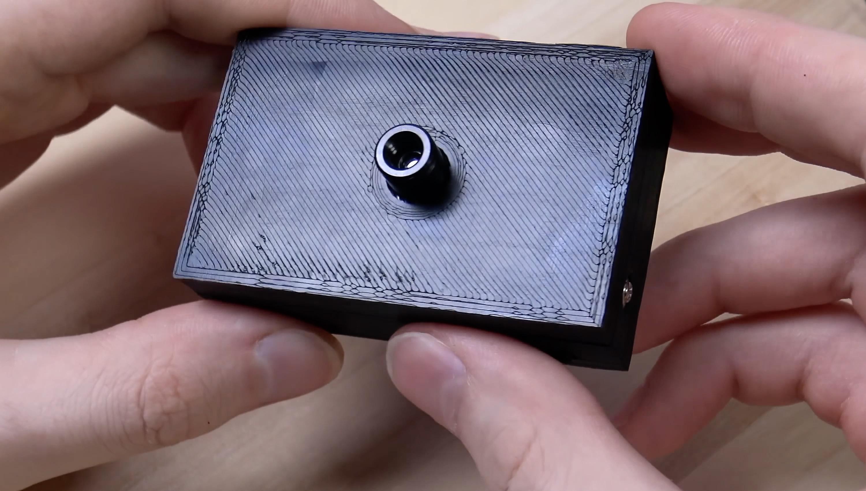
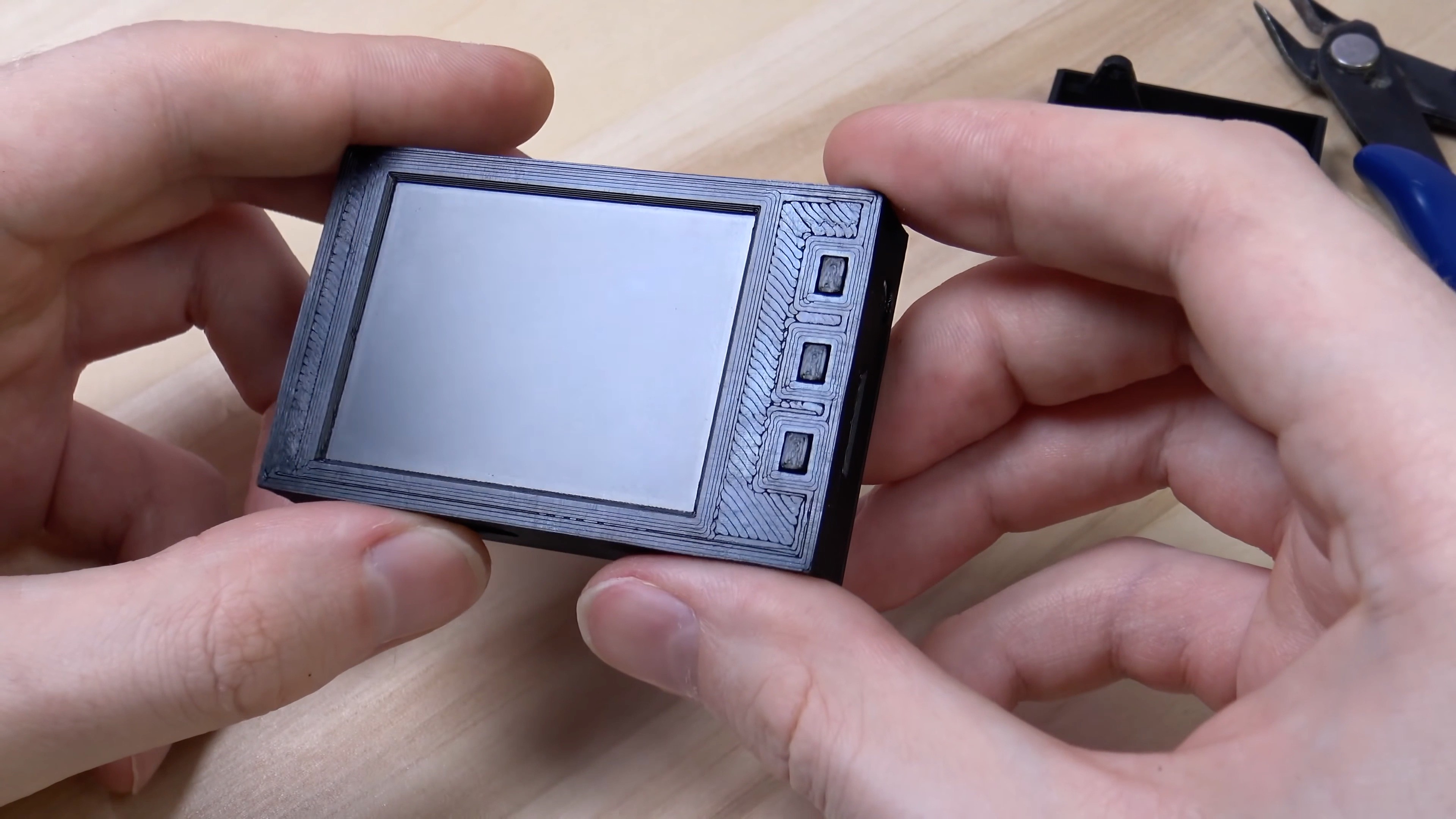
Case
By the time the case was made, I had no experience in designing models for 3D printing, but I had experience in SketchUp.
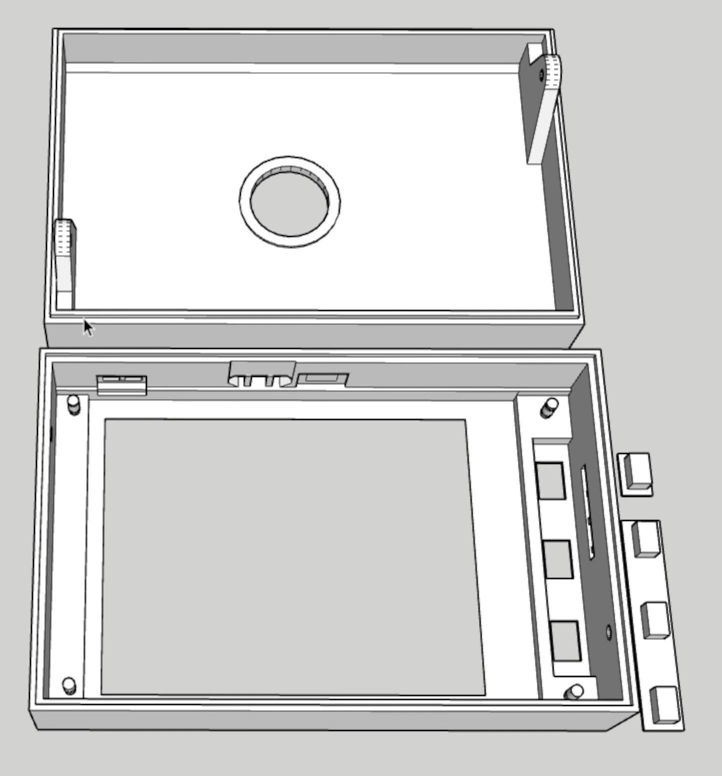
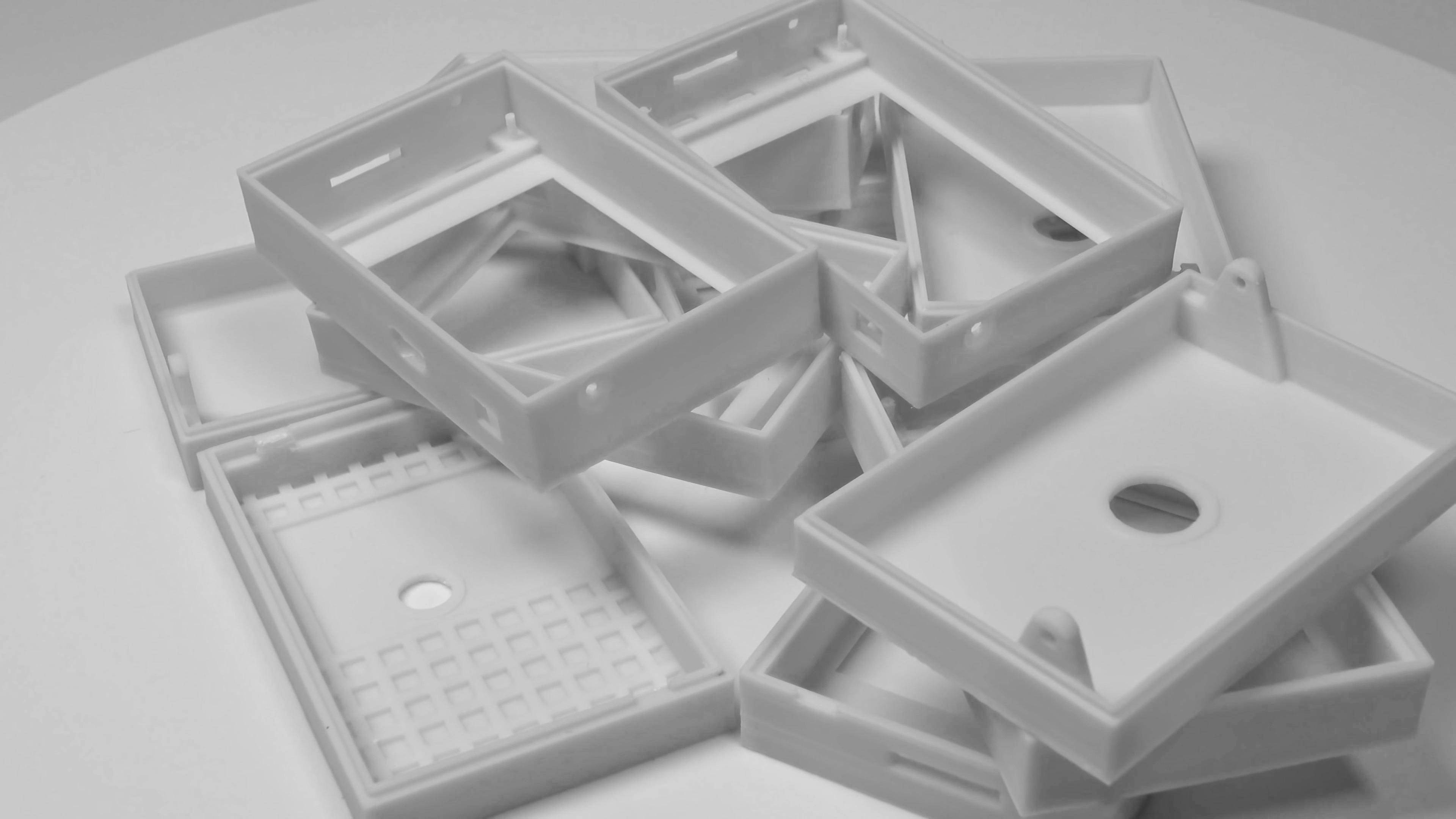
I spent a lot of time designing case, and after 12 or 13 tries, I got a result that I was happy with.
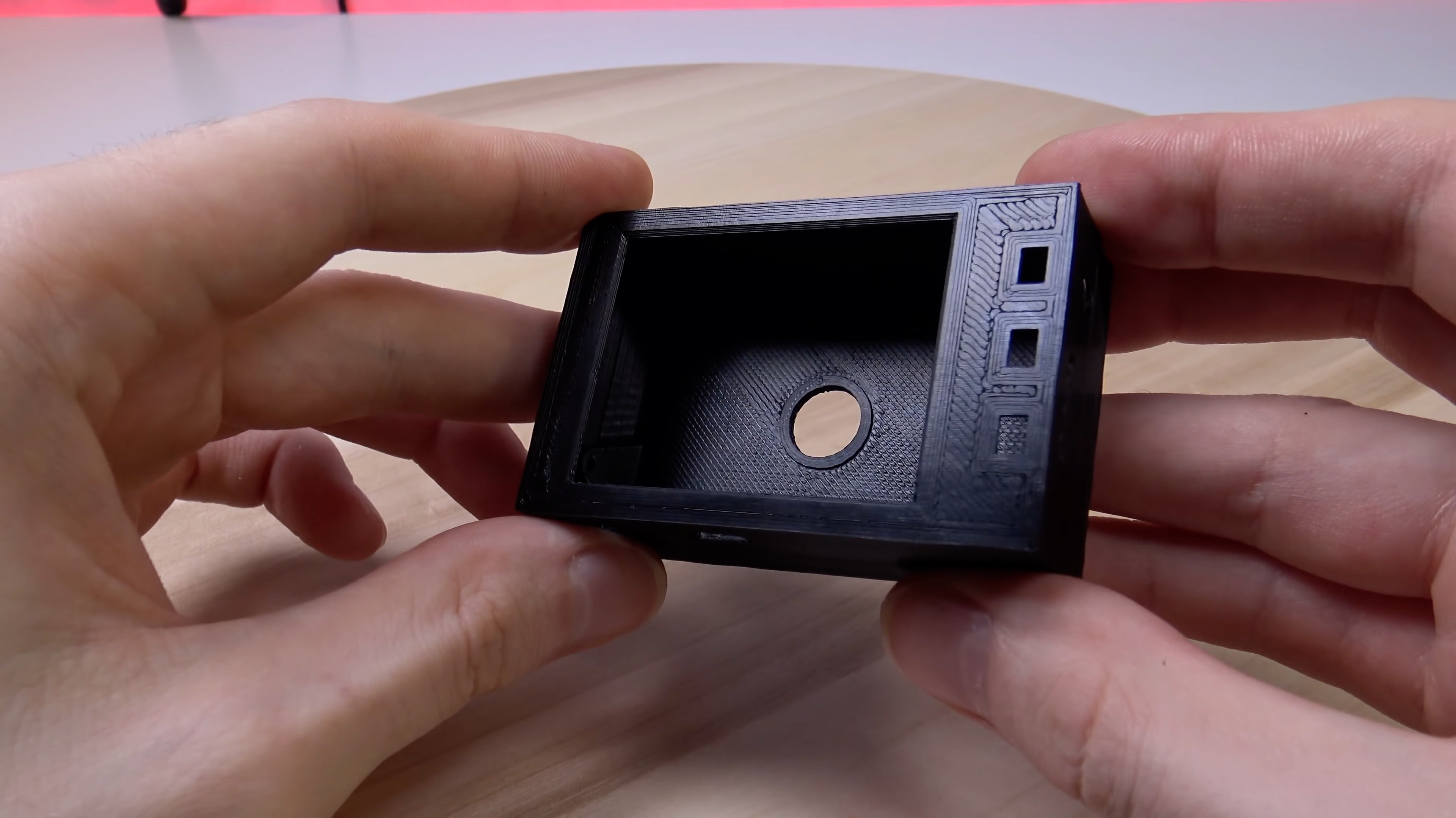
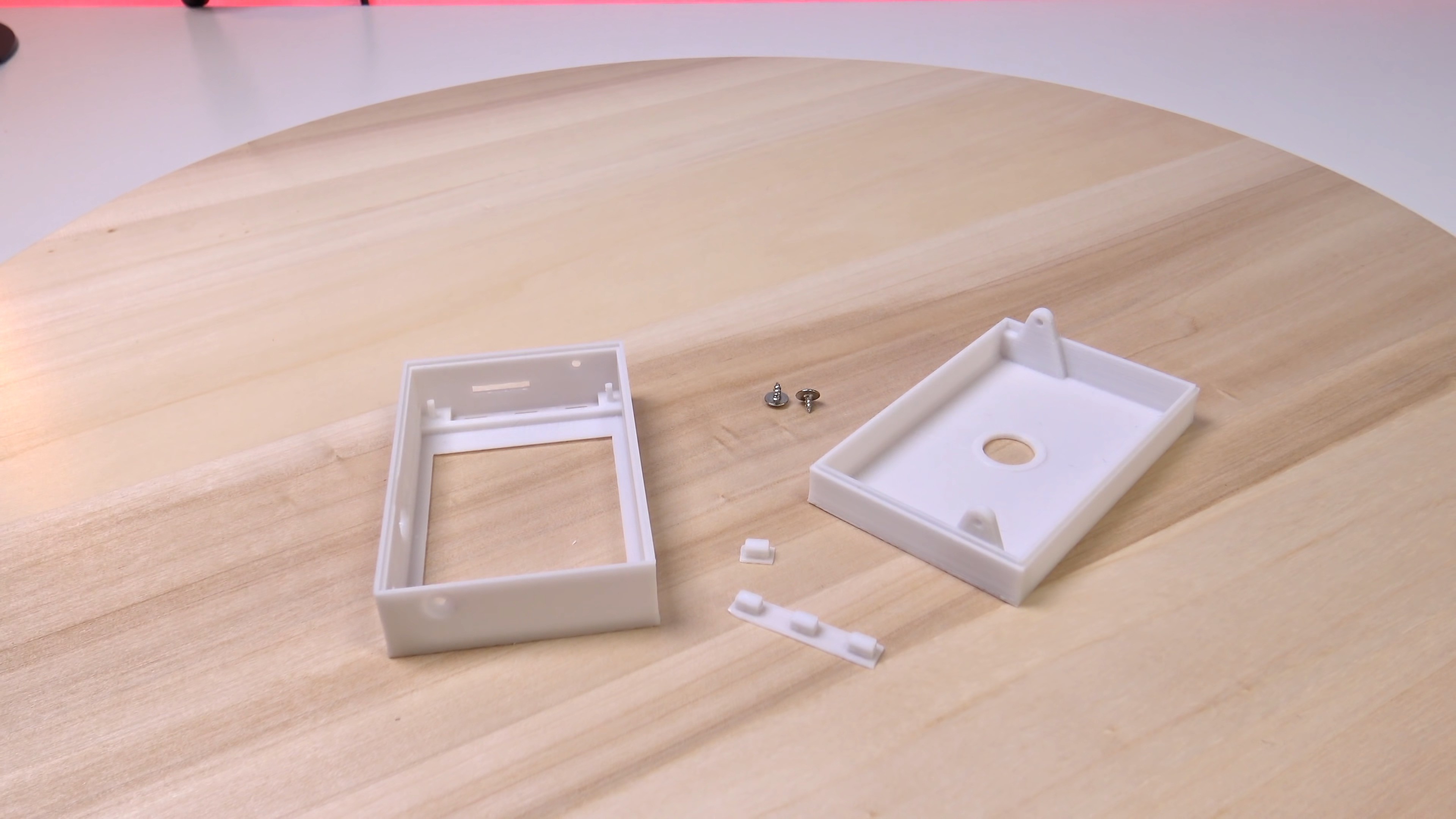
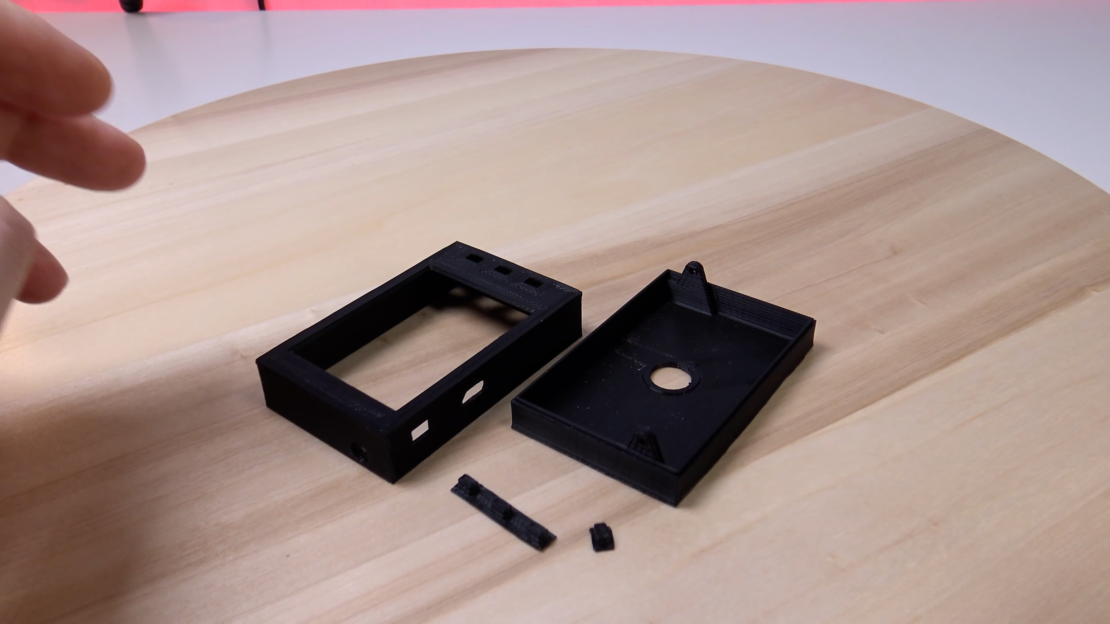
The case consists of 2 parts - front and back. They are held together with 2 small screws. I tried to use latches, but they often broke.
For buttons, I designed pushers: one large for the 3 front buttons and other single for the POWER button. There is no hole for the BOOT button in the case. It is not needed during operation.
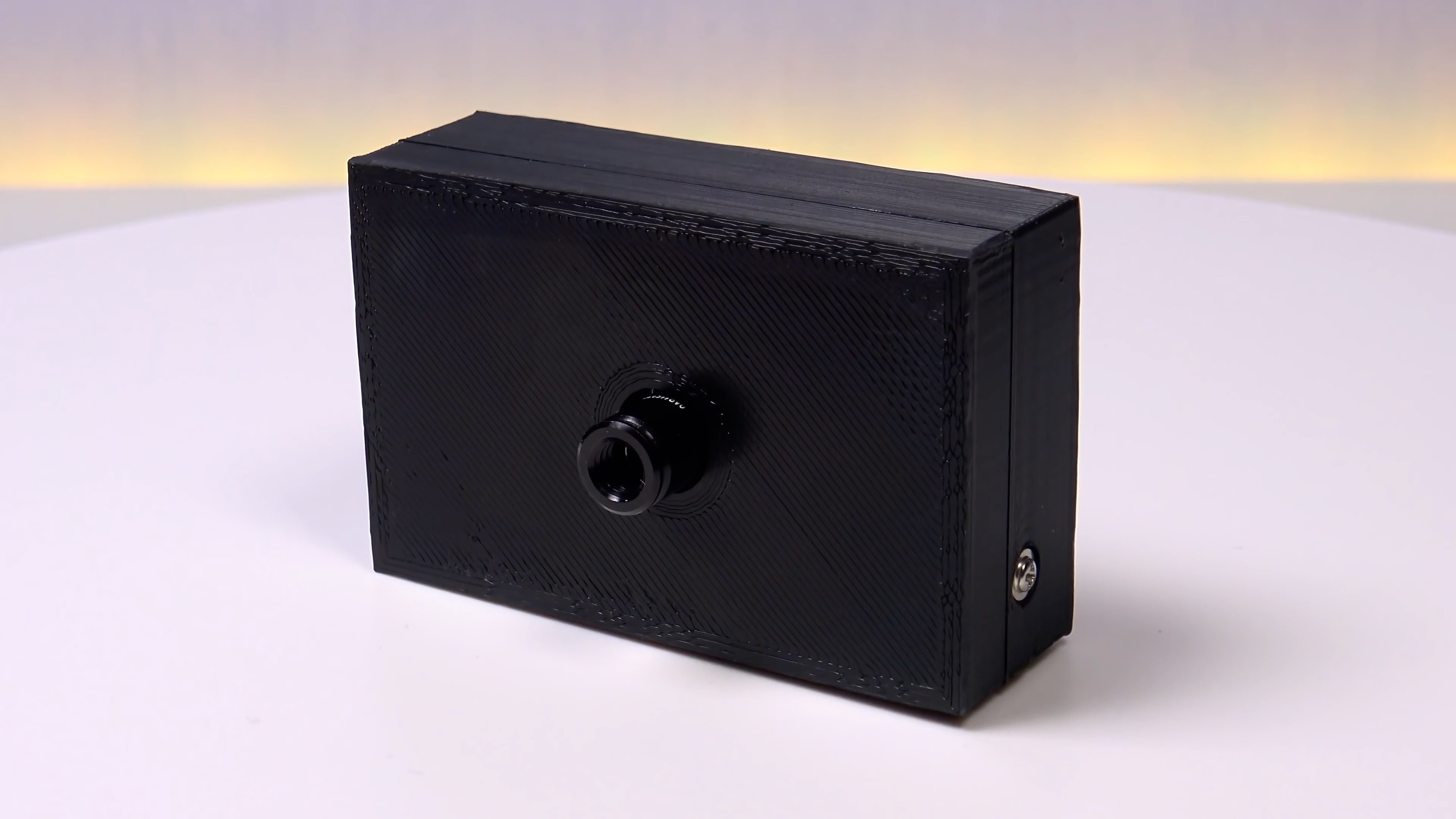
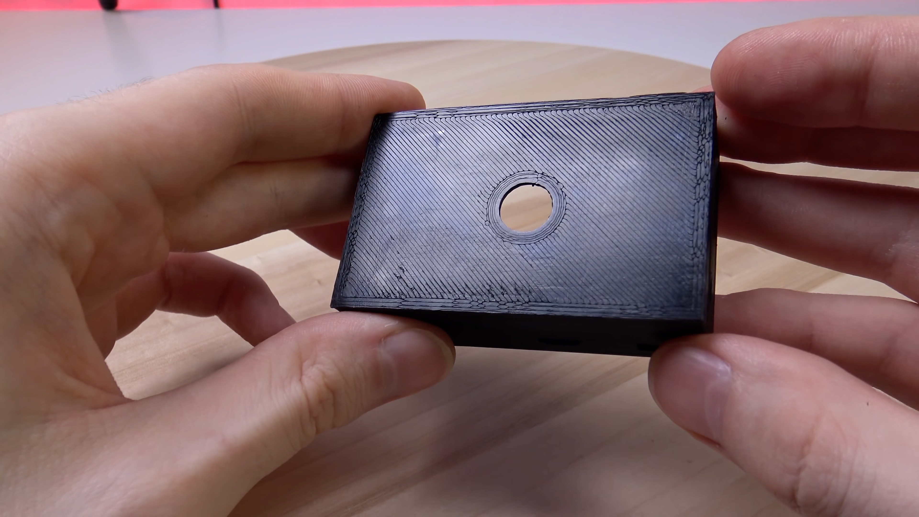
I printed the case out of ABS plastic on a very cheap Anet ET4 printer.
White case:
Black case:
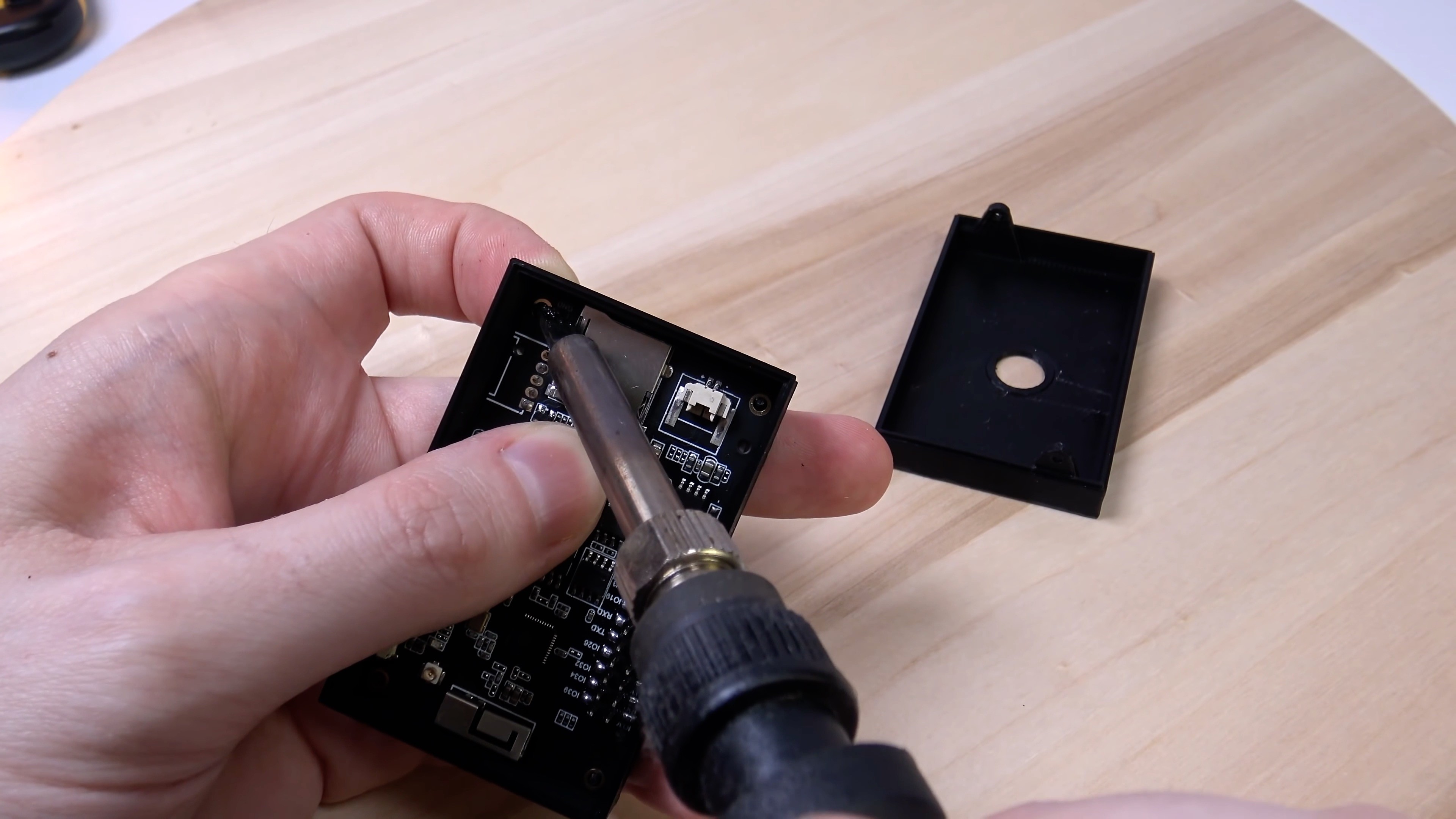
The assembly begins with the installation of the TTGO T4 board in the front of the case. The board is inserted and fixed by melting with a soldering iron 4 pins on the case. I additionally fixed the board with hot glue, although this is not necessary. Before installing the board, do not forget to install pusher for the 3 front buttons.
Next, you need to connect the battery and connect the back board to the expansion connector on the TTGO T4 board.
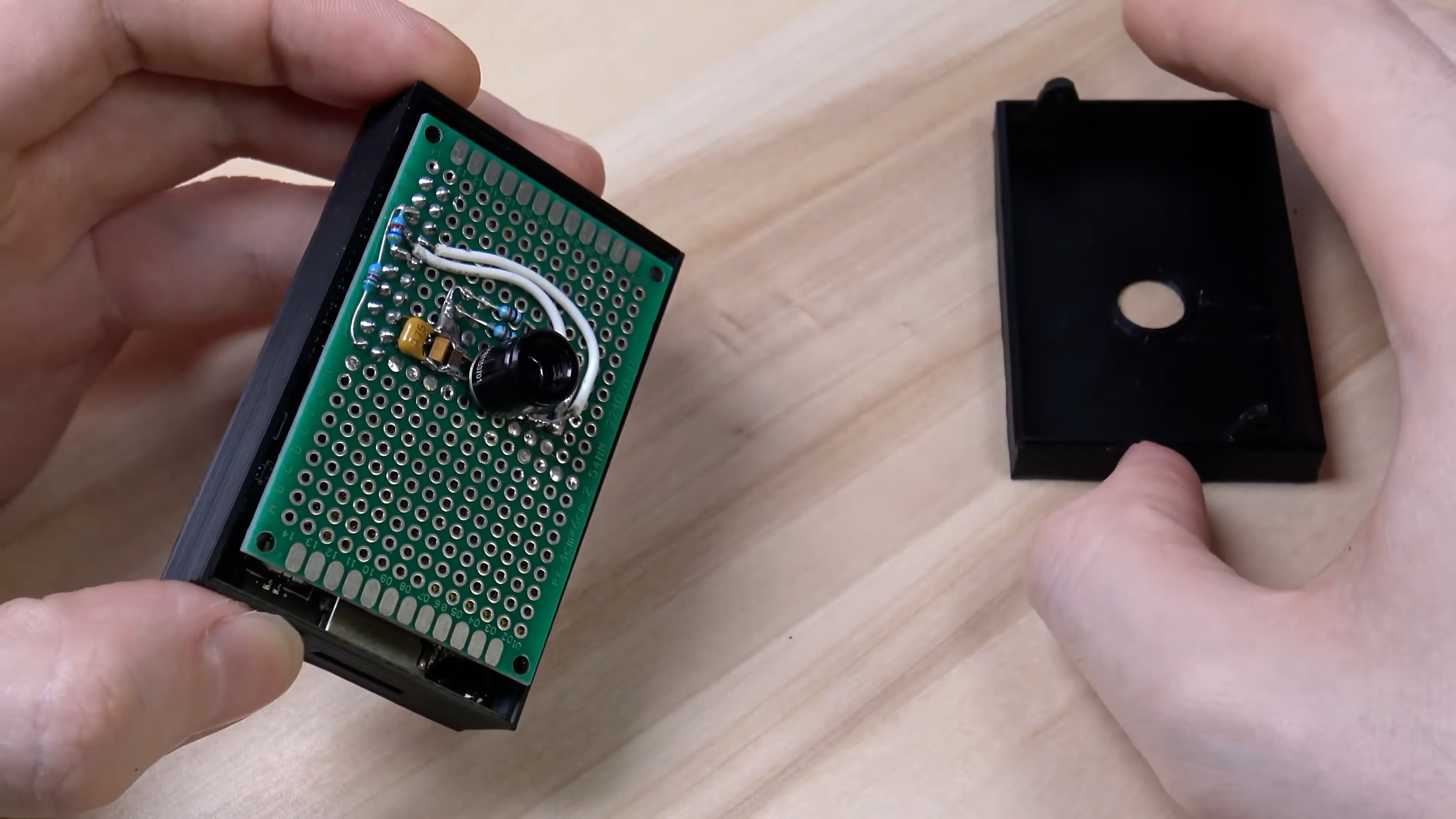
The last thing to do is attach the back of the case and fix it with 2 self-tapping screws.
End result looks like this: