 Pierre-Loup M.
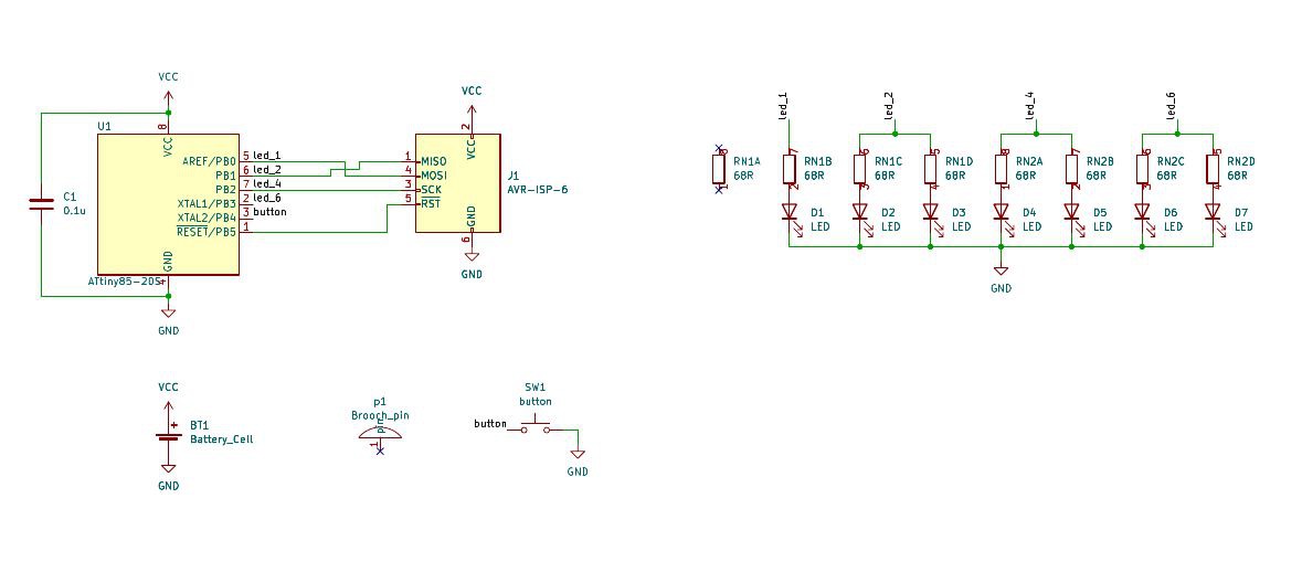
The badge have six different modes, which are :
- Throw a dice : each push on the button will make the dice blink several random number, then stop and display for a few seconds.
- Heartbeat, normal : each tree seconds, the leds blink twice, fast then slow, like a heart beat.
- Hearbeat, slow : same, but with a six seconds period.
- Pulse, normal : it simply blinks every three seconds.
- Pulse, slow : same, but with a six seconds period.
- Random : continuous display of random numbers with random fade in and out durations.
Each mode uses fade in and fade out on leds. Mode is changed by long-pressing (more than one second) the button.
Whenever the leds are not lit, the system goes to deep sleep to preserve the (small) cell. More about that in the logs.


 Muth
Muth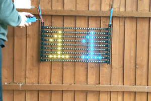
 LordGuilly
I'd buy a couple for my daughter - avid ad&d player.