0%
0%
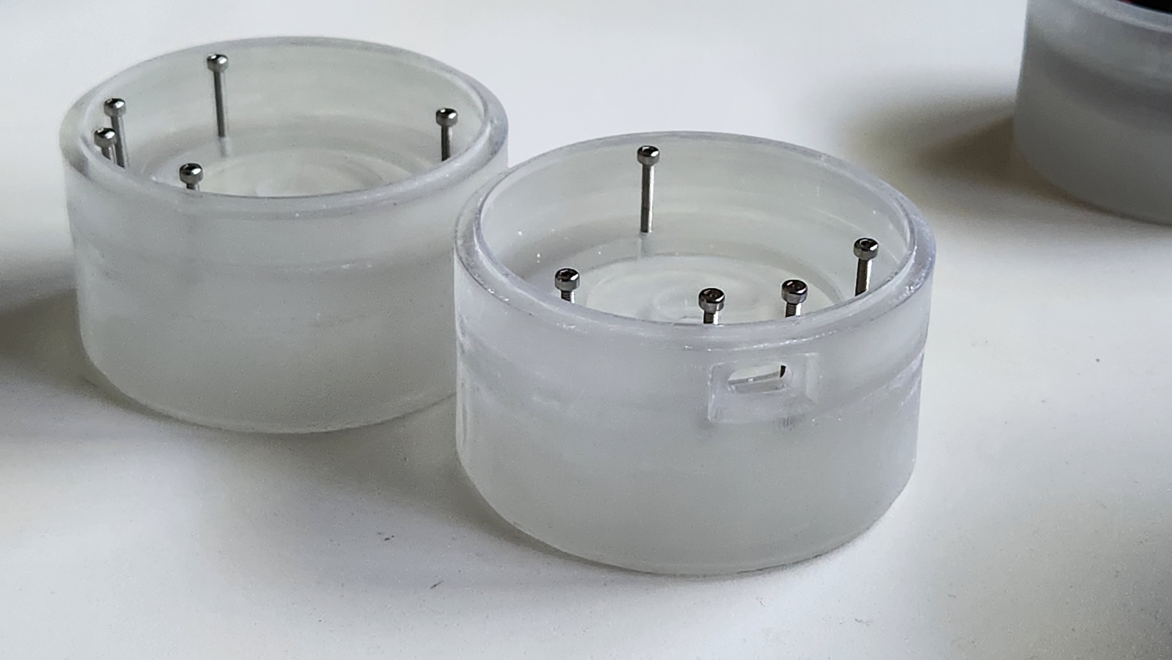
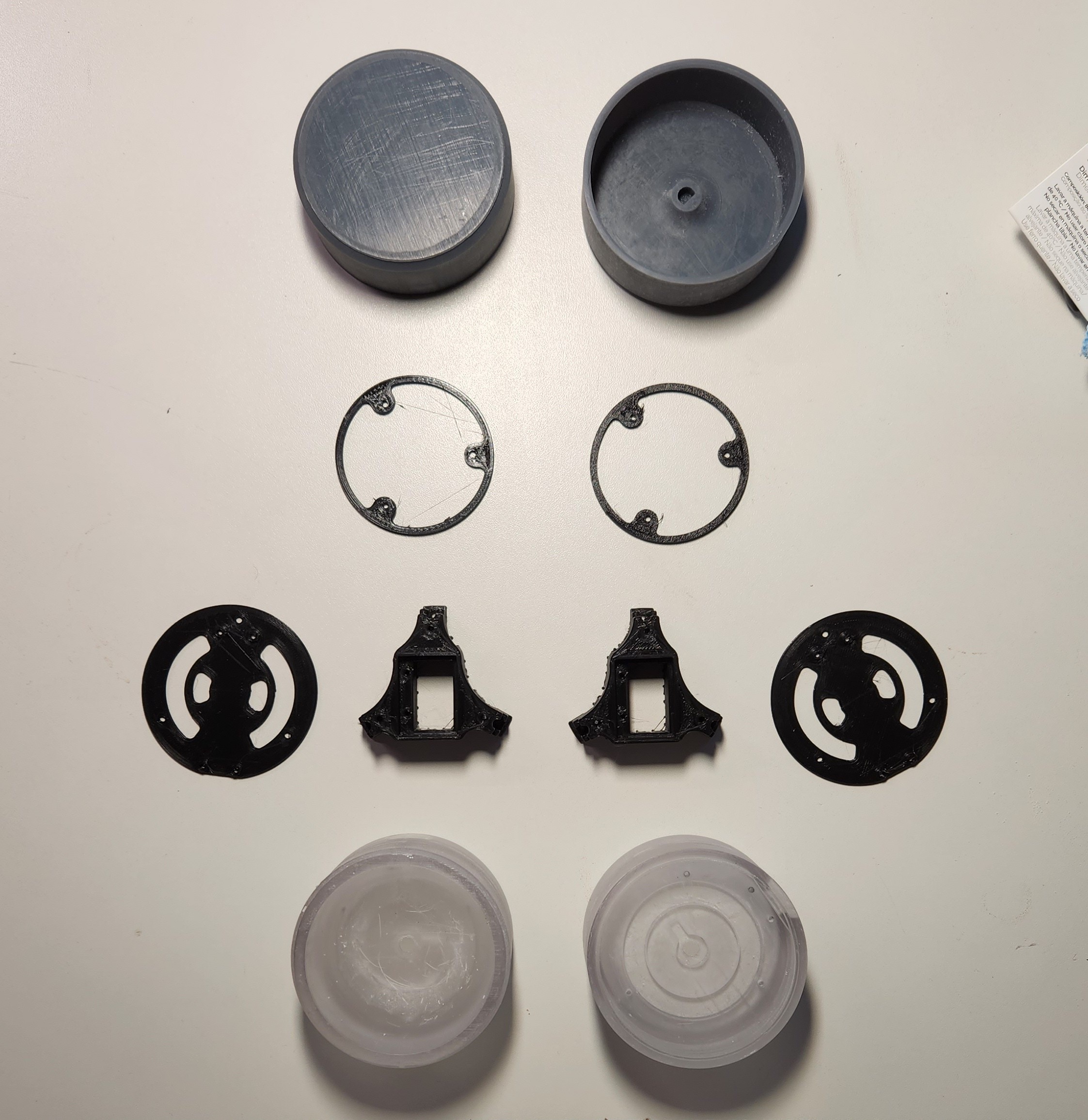
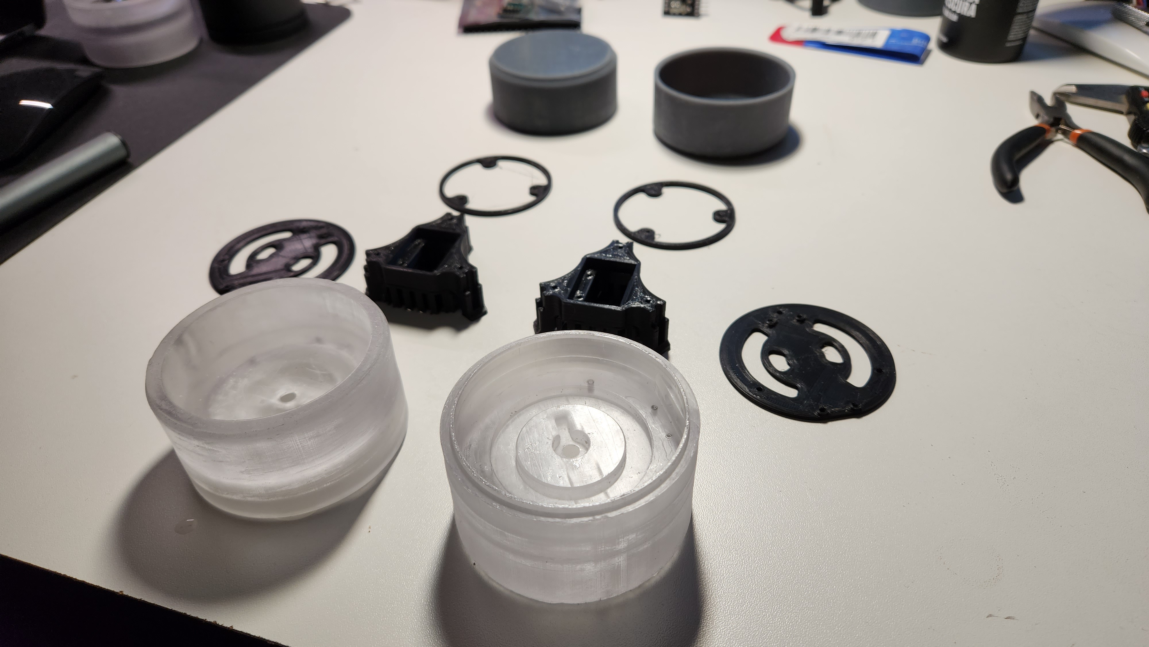
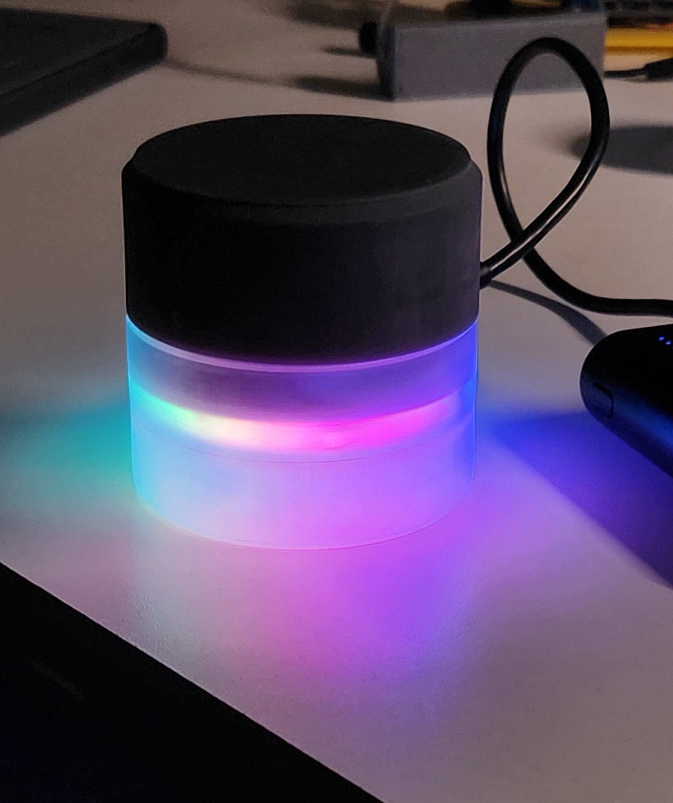
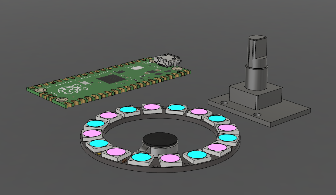
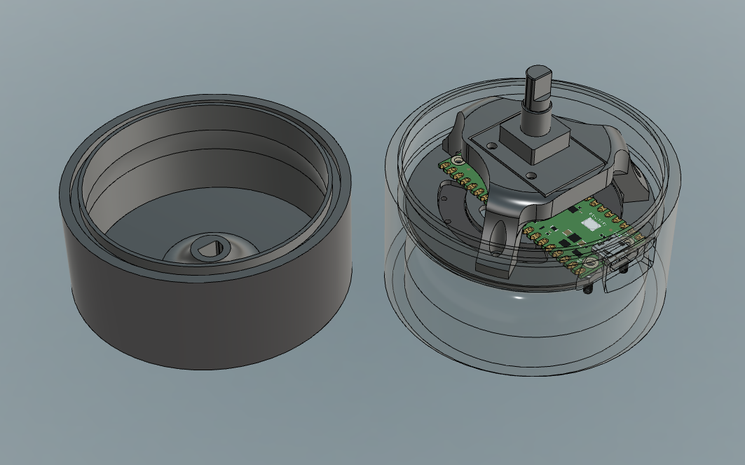
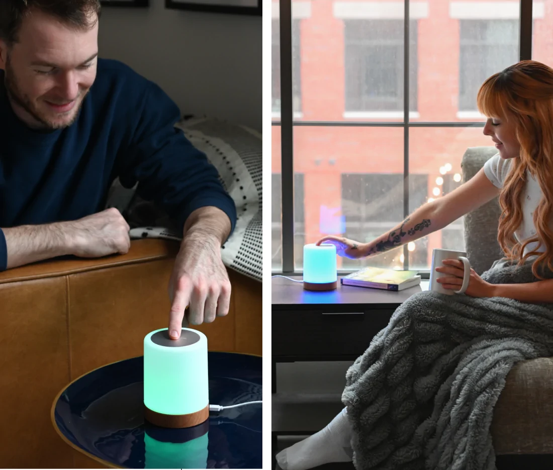
DIY distance lamps
This project combines 3D printing, some electronics integration and clever programming to enable two remote lamps to be in sync.
 Maximiliano Palay
Become a Hackaday.io member
Already have an account? Log in.
Just one more thing
To make the experience fit your profile, pick a username and tell us what interests you.
Pick an awesome username
hackaday.io/
Your profile's URL: hackaday.io/username. Max 25 alphanumeric characters.
Pick a few interests
Projects that share your interests
People that share your interests


 Joseph Marlin
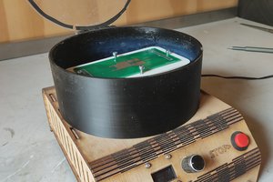
 Jeroen Delcour
 Javier Betancor
From the title i thought they got affected by the distance/location of something, a bit like the elven swords to the bad guys in LotR . Do you think you can fish out the location of a partner or family member or pet and represent it with your project?