 Steve
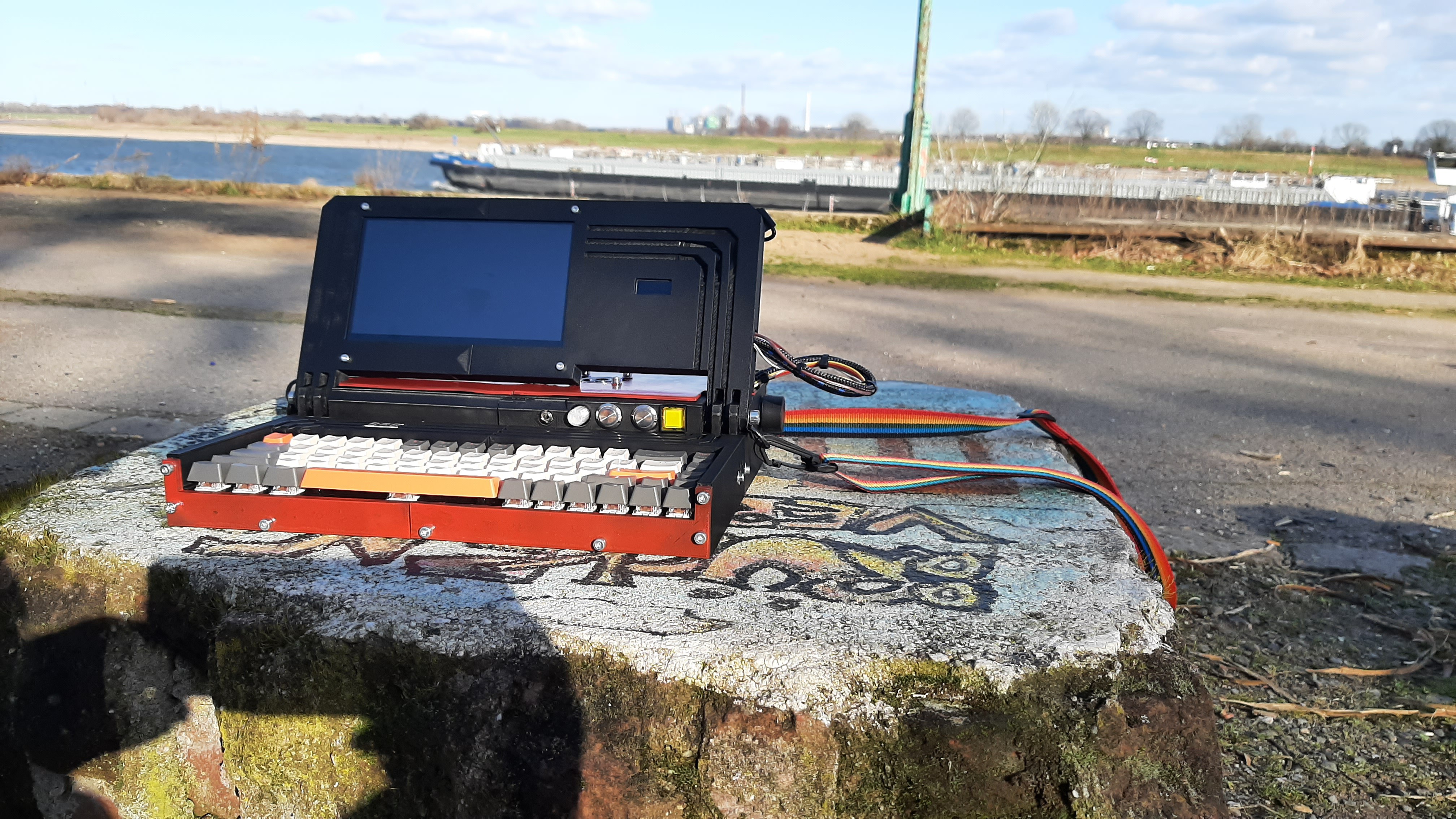
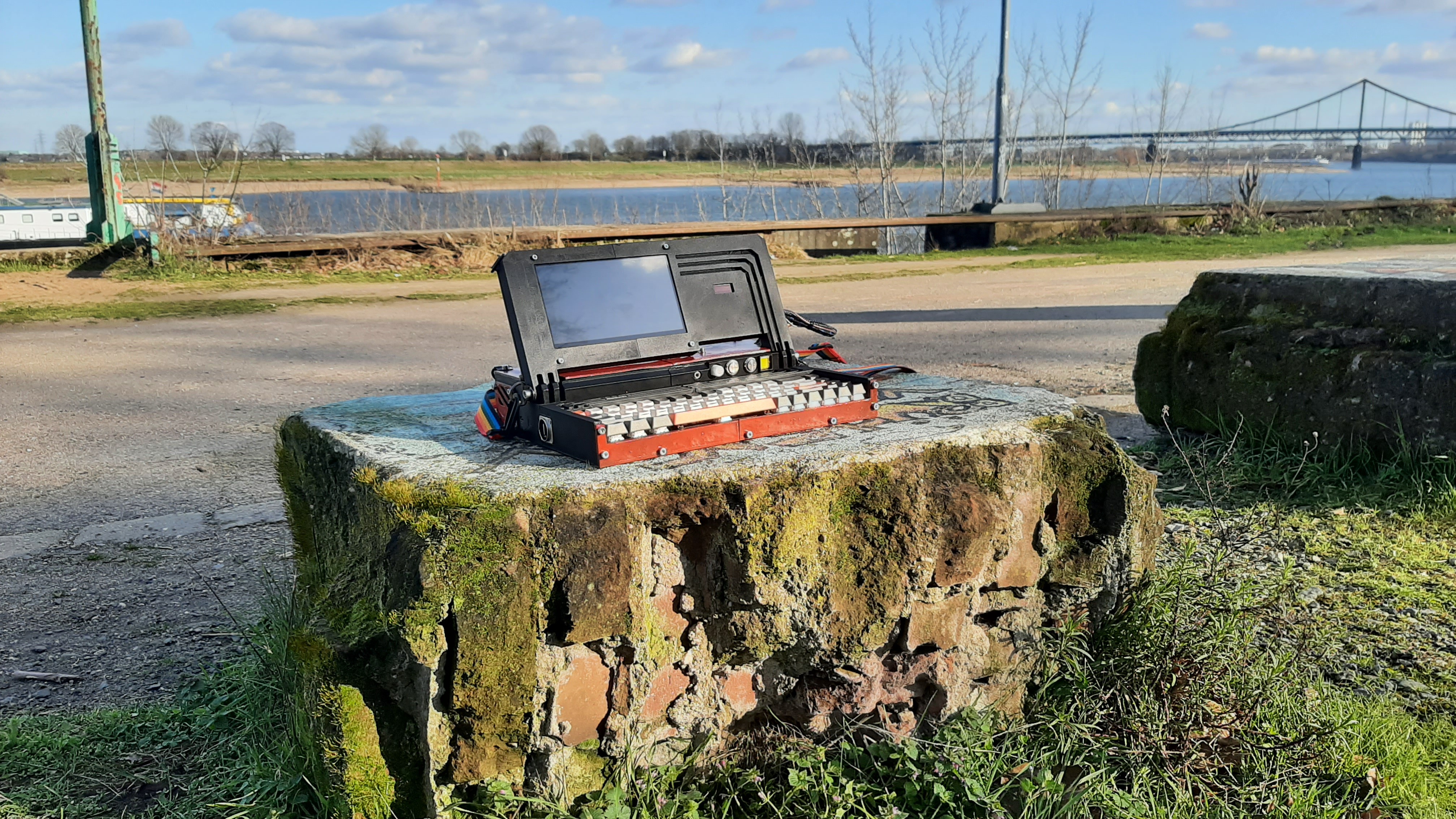
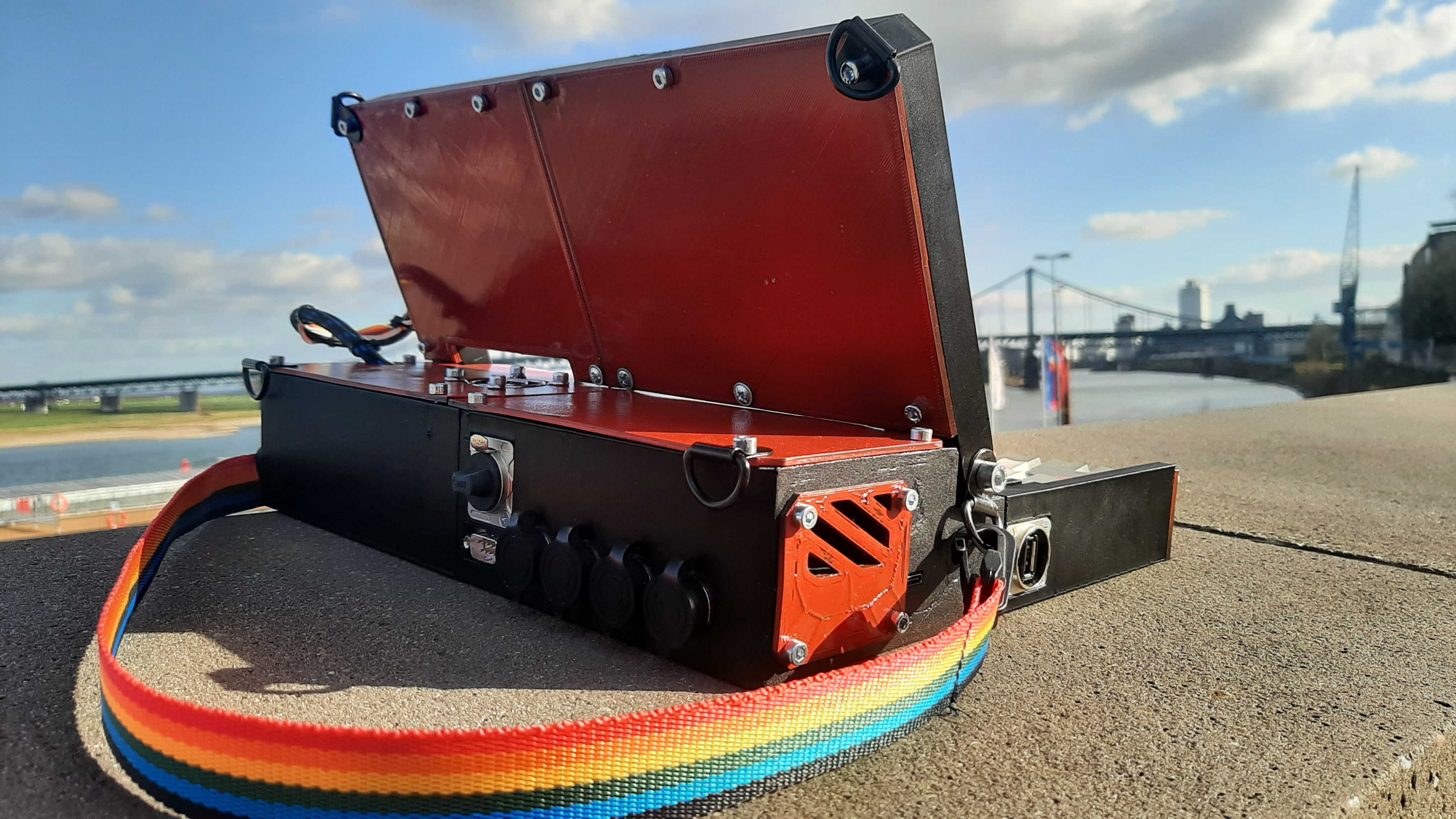
SteveThe main purpose is a mobile programming station, but it also is a viable laptop, or even a emulation station. It teaches you a lot about programming, 3D printing, and hardware tinkering. My initial budget was 100$ but i overshot to around 170$ excluding 3d printing material cost. Which is not ideal but with the end result I'm glad I continued. The whole weight is around 2.5 Kg, so ideal for mobility.
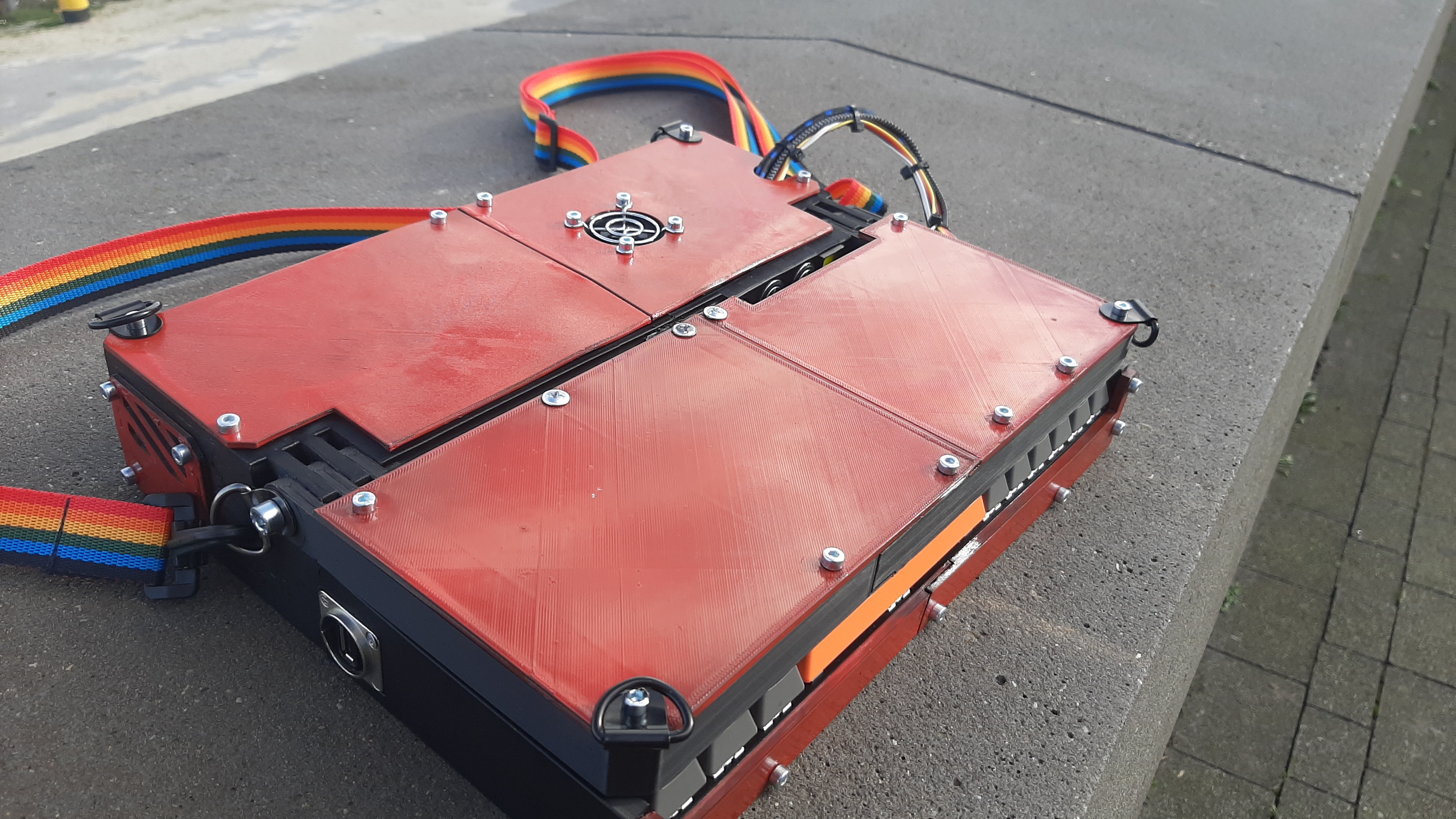
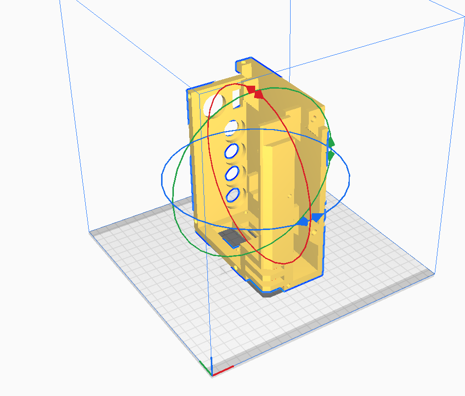
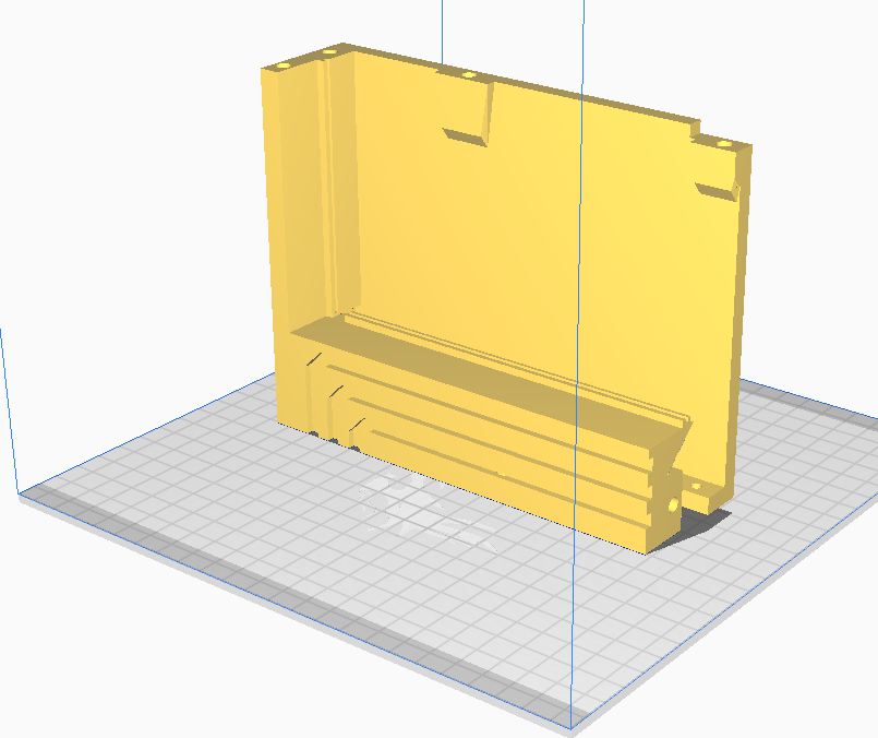
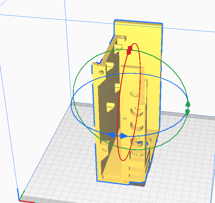
The Body is 3D printed and designed with Blender. Using screw insets the different parts are screwed together.
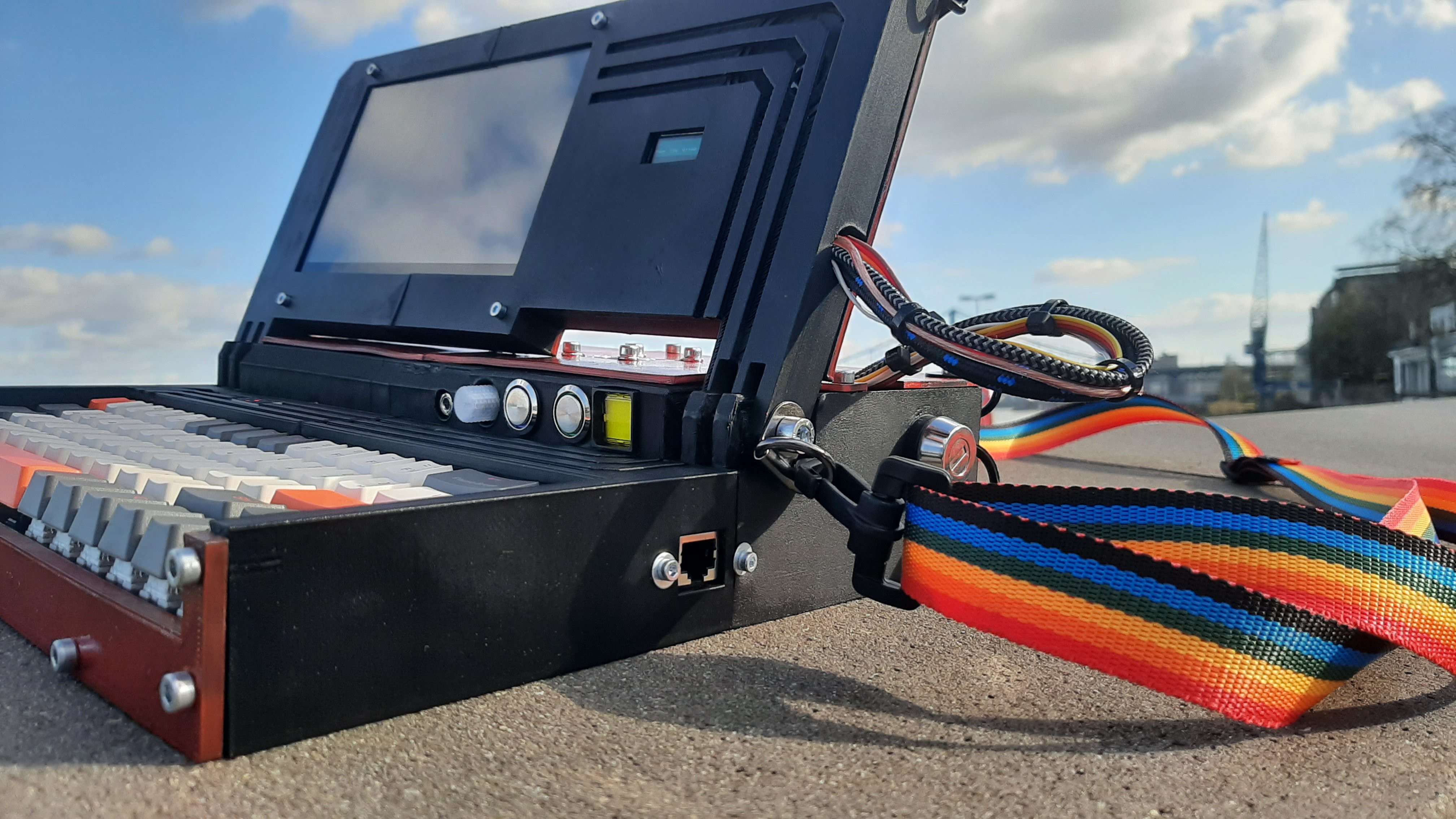
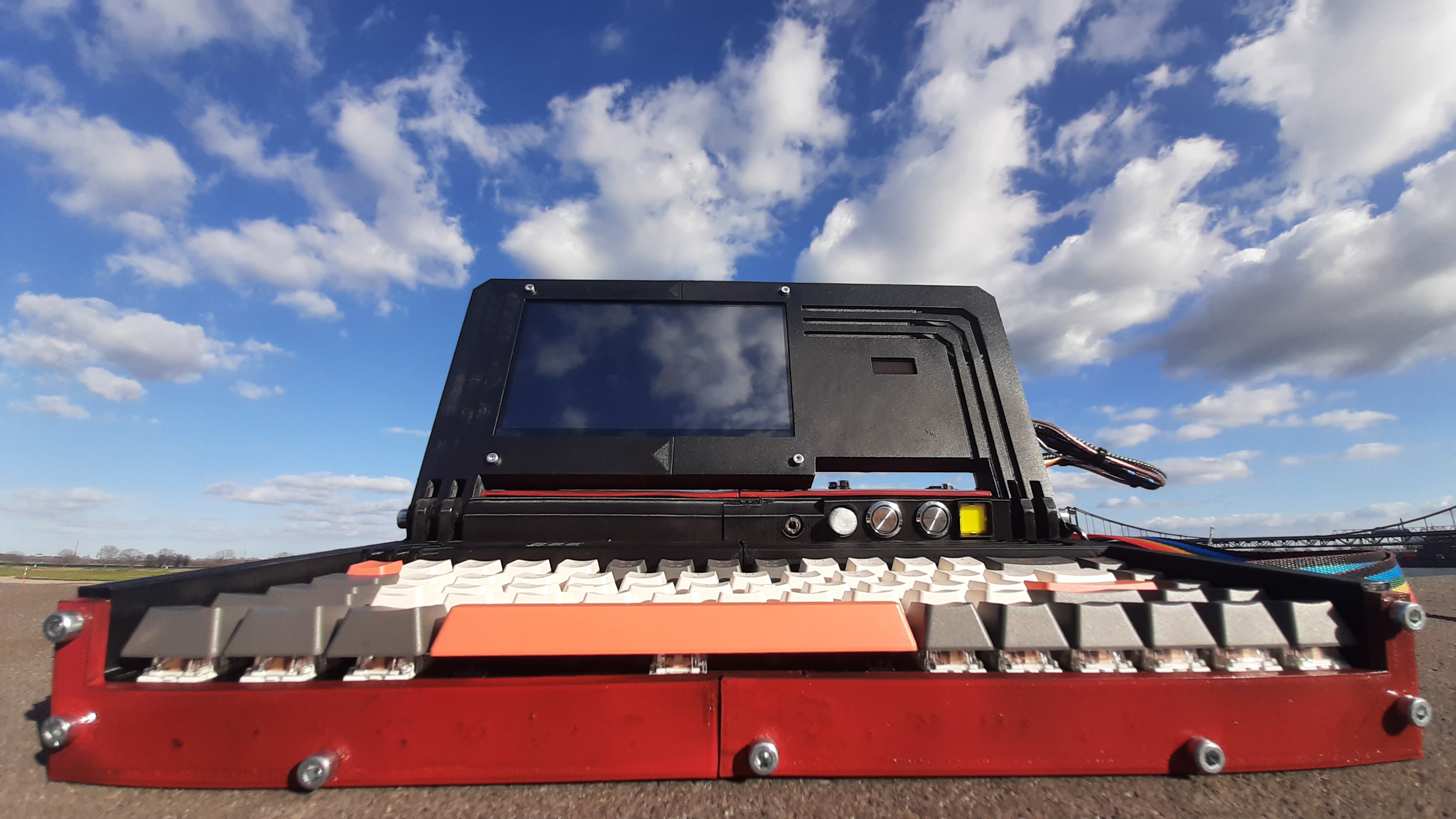
Using a 7" Touch Display, makes a mouse or touchpad redundant. And for typing I used a 68 key wireless mechanical keyboard, wireless is obviously not required, it just made the design easier, because of the absence of a cord.
Powered by a 20.000 mAh powerbank, the Pi has a running time of about 7 Hours with the display on. There is a small 128x32 OLED stat screen on the right side of the main screen displaying CPU usage, temperature and RAM usage. Internally hidden is an DS3231 RTC, for real time even with no Internet connection.
I will in the future retro fit it with a SDR.
It supports external I2C, SPI and UART devices/expansions, via plugs on the back:

-I2C is intended for Sensors and Displays, but there is nothing that stops you from making your own expansions, like a GPIO expansion or LED lights, etc.
-SPI is the same, I have no use for now but having it in advance is always best.
-UART can and will be used for talking to an Arduino for example. But it can be used for all serial devices that use 5V.
The rest of the connectors are the XLR digital stereo audio output and the 6-pin GPIO output for PWM and frequency generator.
I don't have any expansions right now but will soon make some.
The hinge screws have rings attached for an optional, but highly encouraged shoulder strap, making the carying much easier.

The main power is enabled by the side mounted key switch:
Here is a short demontraition video:
Some more Pics:


 CircuitMonster
 Michael Gardi
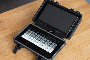
 jefmer
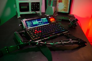
 Leandra Christine
Absolutely love this! I’ve loved all of Gibson’s books since Neuromancer first came out. I have an Ender 3 v2. I have a couple of Pi’s. Mechanical keyboards are the only one’s worthy of use. Excellent design, thanks so much for sharing. I want to take this project on so bad.