Here is a photo of the working Real Memory:
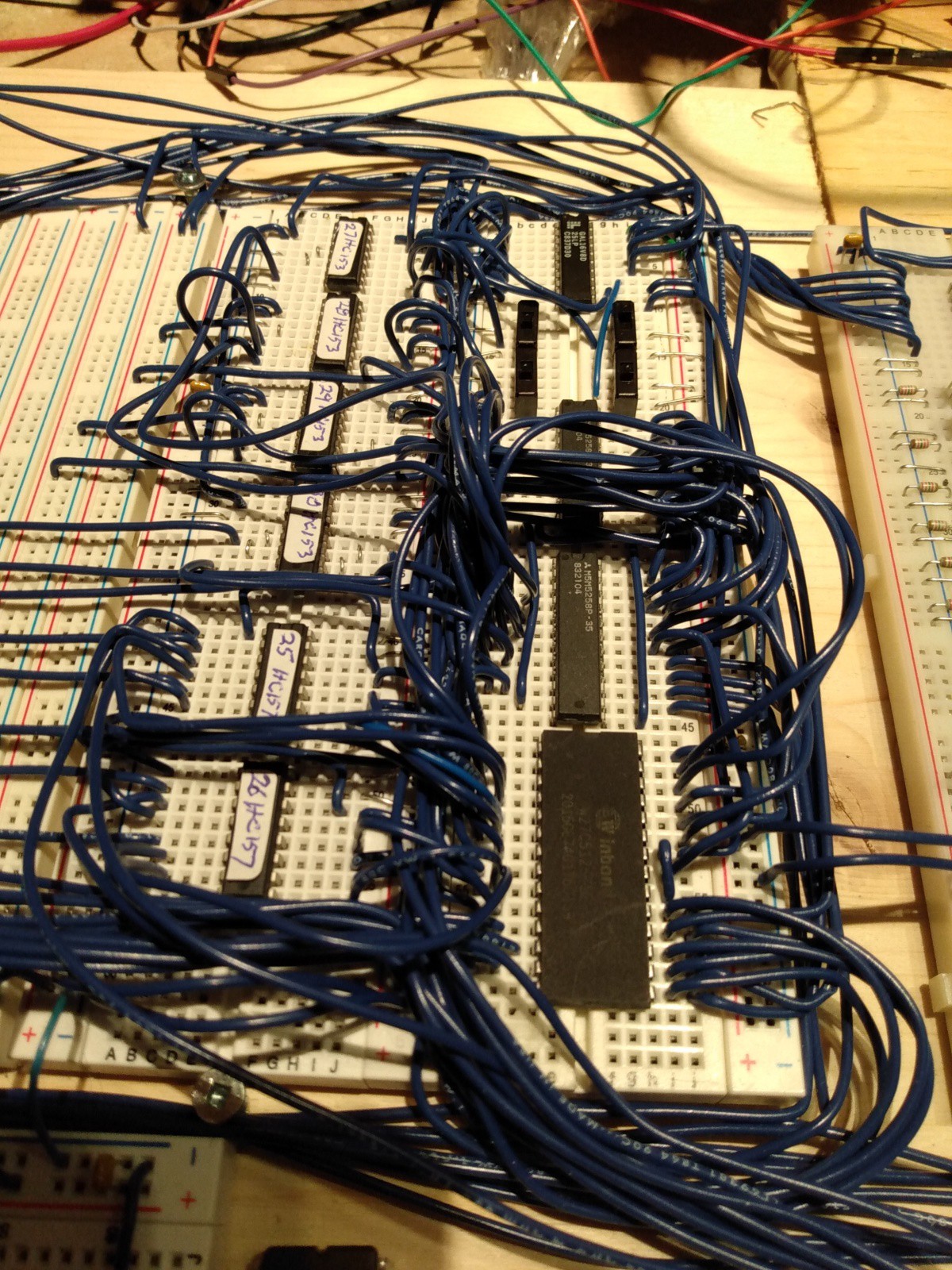
Foreground right the 64Kx8 EEPROM. Above that the two 64Kx4 RAM chips (the upper one partially obscured by the wires). Above that the four switches which are standing in for the memory mode flip-flops. And above that, the 16V8 GAL. On the left are the six multiplexer chips.
On to the design
With the keyboard PCB in hand, if not yet assembled, it was time to move on to Real Memory. But first we need to talk a bit about the memory layout of the MCM/70 production machine, the memory layout of the original MCM rack machine, and about the proposed memory layout for my Rack8 machine.
The address space in the production MCM/70 is laid out thus:
- X'2000' - X'3FFF' - 8K RAM - the workspace for the user.
- X'1800' - X'1FFF' - 16 ROM banks of 2K each, only one of which can be active at a time.
- X'0000' - X'17FF' - 6K ROM of frequently used routines.
For the Rack8 machine clearly we want to have RAM where the MCM rack machine had RAM and EPROM where the MCM rack machine had EPROM. But wait! There's more! In addition to working like the old MCM rack machine I would like the Rack8 to be able to run MCM/APL by flipping a switch. So, after a lot of cogitation we have the following design criteria:
For the low 2K - X'0000' through X'07FF' nicknamed "LOW" - we want to be able to have:
- A simple loader in EPROM suitable for startup in "Rack" mode, or
- The first 2K of MCM/APL for running APL, or
- RAM for doing development work
For the next 6K - X'0800' through X'1FFF' "nicknamed "MID" - which includes the bank area we want to be able to have:
- MCM/APL in EPROM, or
- RAM for development
And the high memory area - X'2000' - X'3FFF' nicknamed "WS" (because it is the users WorkSpace) - is always RAM.
Then what?
So we've got what we want figured out. Now how do we control it? The suggestion is three toggle switches and three flip-flops. The flip-flops will control who gets what in terms of EPROM and RAM, and those flip-flops will be settable by issuing an I/O command so we can change the setup dynamically. The toggle switches will control what the flip-flops get set to when the CPU is reset.
The three flip-flops are:
- LOWRAM.: If True the LOW memory area is RAM, otherwise it is EPROM.
- LOWAPL: Has no effect unless LOWRAM is False. If True then LOW memory has MCM/APL in EPROM, if False then LOW memory has a simple loader in EPROM.
- MIDAPL: If True the MID memory has MCM/APL in EPROM, if False them MID memory is RAM.
Note that if all three switches are False then we have something very much like the old MCM rack machine: all RAM except for the low 2K which has the loader and some basic routines.
But wait - there is even more! Flip-flops come in pairs and we are using three so the remaining one is burning a hole in our pocket, so to speak. And in our 64K memory we have a bunch left over. So we invent the flip-flop ALTWS. When True it selects an alternate workspace in RAM. Thus we have, in effect, two workspace banks: the regular one and the alternate one. This is not something that the original rack machine had, and I have no idea what it might be used for, but this is a fun little project so I'm putting it in for fun.
Then how?
So how do we implement this memory scheme? For RAM we are using two M5M5258 64Kx4 chips, and for EPROM we are using one 27C512 64Kx8 chip. For our purposes we consider these chips to consist of 32 chunks of 2K each which we allocate like this:
| Address | EPROM | RAM |
|---|---|---|
| F800 | APL Bank F | Bank F |
| F000 | APL Bank E | Bank E |
| E800 | APL Bank D | Bank D |
| E000 | APL Bank C | Bank C |
| D800 | APL Bank B | Bank B |
| D000 | APL Bank A | Bank A |
| C800 | APL Bank 9 | Bank 9 |
| C000 | APL Bank 8 | Bank 8 |
| B800 | APL Bank 7 | Bank 7 |
| B000 | APL Bank 6 | Bank 6 |
| A800 | APL Bank 5 | Bank 5 |
| A000 | APL Bank 4 | Bank 4 |
| 9800 | APL Bank 3 | Bank 3 |
| 9000 | APL Bank 2 | Bank 2 |
| 8800 | APL Bank 1 | Bank 1 |
| 8000 | APL Bank 0 | Bank 0 |
| 7800 | - | - |
| 7000 | - | - |
| 6800 | - | - |
| 6000 | - | - |
| 5800 | - | ALTWS |
| 5000 | - | ALTWS |
| 4800 | - | ALTWS |
| 4000 | - | ALTWS |
| 3800 | - | WS |
| 3000 | - | WS |
| 2800 | - | WS |
| 2000 | Loader | WS |
| 1800 | - | MID RAM |
| 1000 | APL | MID RAM |
| 0800 | APL | MID RAM |
| 0000 | APL | LOW RAM |
In our RAM there is enough unused space that we could have an alternate alternate workspace, but lets not get carried away here. And there is a bunch of unused EPROM but we are using more than 32K so I'm happy enough to leave that as is.
The Gory Details
The schematic of the Real Memory is here (PDF). You can see why I wanted to have the CPU itself and Simple Memory working before I tackled getting this to work. A great deal of what goes on with memory access is orchestrated by the 16V8 GAL, and you can find the logic for it here. Let's go over this a bit at a time.
The Data Bus is dead simple: it comes from the CPU schematic and goes to both the RAM and EPROM. End of story.
The Address Bus is where the fun happens. The CPU has only 14 address bits but our memory chips have 16 bits so, with the aid of some multiplexers and the GAL we develop the Effective Address. We further divide that Effective Address into Low (the low 8 bits), and High (the high 8 bits).
Effective Address Low is the simpler of the two. It always comes from the CPU unless the SelfScan is accessing memory in which case Effective Address Low comes from the SelfScan interface. The SelfScan is soon going to get its own log entry but suffice to say that it is a memory mapped display device which need to get a byte of data from memory every 140uS. If the CPU were doing that it would be so busy servicing the SelfScan that it wouldn't have time for much else. So, yes, we have to use hardware to service the SelfScan. The two 74HC157 muxes, U25 and U26, look after selecting the source for Effective Address Low.
Effective Address High is rather more complicated. There are four mode of access that it needs to deal with:
- Bank (we are accessing memory in the range X'1800' - X'1FFF')
- Loader (we are accessing the loader EPROM)
- SelfScan (we are accessing RAM for the SelfScan)
- Normal (not Bank, Loader, or SelfScan)
For each of our four modes the Effective Address High bits need to be supplied per this table:
| Address Bit | 00 Bank | 01 Normal | 10 Loader | 11 SelfScan |
|---|---|---|---|---|
| EA15 | 1 | 0 | 0 | 0 |
| EA14 | Banklatch3 | ALTWS | 0 | 0 |
| EA13 | Banklatch2 | A13 | 1 | 1 |
| EA12 | Banklatch1 | A12 | 0 | 0 |
| EA11 | Banklatch0 | A11 | 0 | 0 |
| EA10 | A10 | A10 | A10 | 0 |
| EA9 | A9 | A9 | A9 | 0 |
| EA8 | A8 | A8 | A8 | 0 |
The Effective Address High multiplexers (U27 - U30), under control of the GAL, select the various bits per the above table.
Notes and caveats:
- Banklatch is the four-bit latch, set via an I/O instruction, which says which bank is to be active. No I/O is implemented yet so for now these bits are hard wired to 0 but everything is ready once the real banklatch is working.
- The SelfScan is mapped to memory starting at X'2022' thus, if accessing data for the SelfScan, the Effective Address High is always X'20'. The SelfScan memory is only 222 bytes long so the rest of the Effective Address come on Effective Address Low.
- ALTWS is true if we are accessing the Alternate Workspace; it just moves workspace accesses up into the alternate space.
- A signal to tell the EPROM when to read.
- Signals to tell the RAM when to read and write.
- A signal to the Effective Address Low muxes saying which input to select.
- Two signals to the Effective Address High muxes saying which input to select.
- The ALTWS signal based on the ALTWS flip-flop and other considerations.
And somewhat remarkably, after a very modest bit of debugging, this all works. Next up is the SelfScan interface.
Discussions
Become a Hackaday.io Member
Create an account to leave a comment. Already have an account? Log In.