 Marcin Saj
Update: Flip-disc displays will be available soon on Kickstarter.
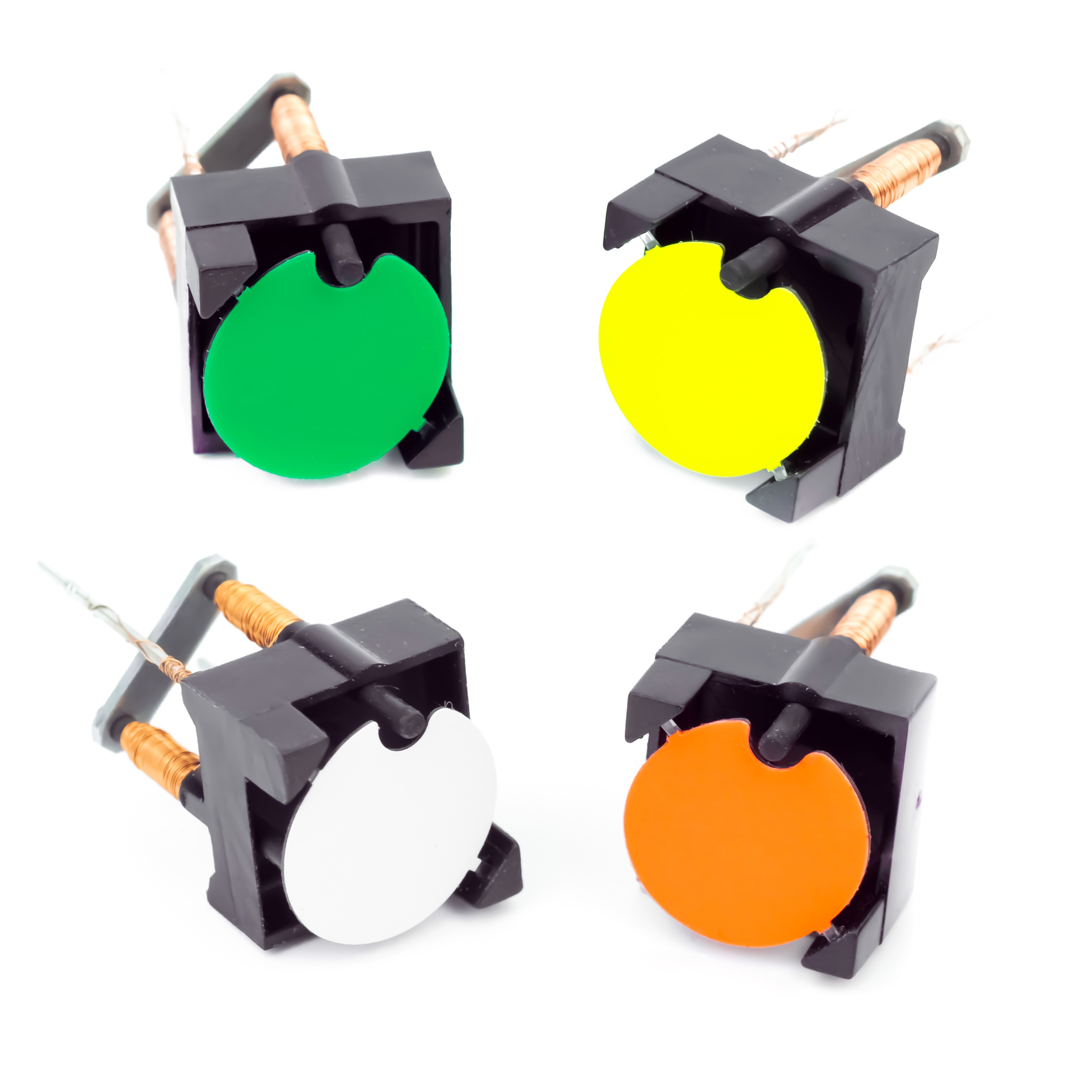
Flip-disc display it is electromagnetic display, a passive technology, because it only needs a short current pulse to flip the disc. The disc remains in the set position without any other energy needed.
There are different types of flip-disc displays, they differ in the design of the rotating discs and size. The control of all displays is similar and mainly comes down to power supply. I would like to focus on one selected type of display, since I have experience with them and have already built several interesting projects based on these displays.
How it is Built
A flip-disc display, is an electromechanical display that consists of a small physical disc with two contrasting colored sides. This disc is called flip dot, flip disc, or simply dot. The dot is usually made of a lightweight material, such as plastic, and is mounted on a surface with small hinges or pivots that allow it to rotate freely.
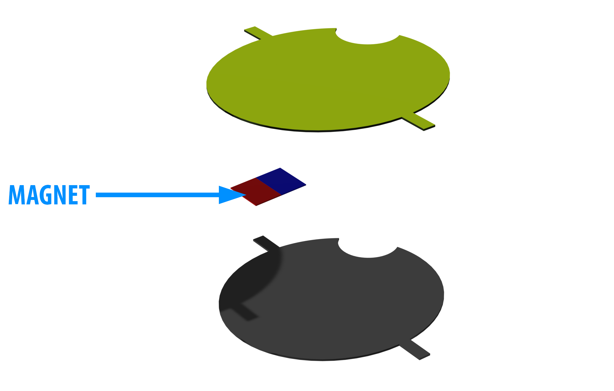
The disc is controlled by electromagnets located beneath the display surface. Between the two layers of the disc, there is a small permanent magnet that interacts with electromagnets.


How it Works
When a current is passed through the electromagnet, it attracts or repels the dot, causing it to flip over and change color. In other words, changing the poles of the electromagnets repels or attracts the magnet embedded in the disc, which causes the disc to rotate.
Let's look at the documentation for the flip-disc display, the documentation says that the recommended power supply is the current option. To flip the disc, we need to power the display with a current pulse of about 0.5A and a length of about 1ms. A simple change of the power polarity on the display leads allows to flip the disc to the desired black/color position.

There are many ways to generate current pulses for a flip-disc display, the easiest way would be to connect the display to a constant power source and only change the polarity. However, this would not be the safest way due to the difficulty of precisely maintaining the parameters of such a current pulse and the danger of damaging the display.
Design assumptions:
- Safe current pulse
- Simplicity and reliability
- Control directly from e.g. Arduino
We need something that first accumulates a charge and then releases a current pulse to our display.
Flip-disc documentation says that the resistance of the electromagnet coil is about 18Ω. Therefore, the control voltage of the "charge accumulator" can be assumed to be 12V (according to the documentation, we will fit in the current range). We can illustrate this with the following diagram:

The pulse shaper power supply consists of two transistor switches and a capacitor. When the CH (charging) line is turned on, the capacitor accumulates charge, then the charge is released when the PL (pulse) line is turned on. A more detailed description of the operation and an example of connection and control via Arduino can be found in the project description.
Once the power supply issue was resolved, there remained the element of controlling the polarity of the current pulse released by the pulse shaper power supply module.
We need to build a so-called display controller that will work with an Arduino board.
There are many solutions that can be used to control the power supply polarity, one of them is the use of the so-called H-Bridge.

Such simple transistor switches are enough to control the polarity of the flip-disc. However, it should be remembered that, this solution is prone to physical damage/burning of the transistors. If we mistakenly turn on both transistors on one side H1 & L1 or H2 & L2 at the same time, the transistors will be short-circuited and damaged. Therefore, you must be absolutely sure that the control code is resistant to errors that can lead to damage to the controller. To avoid a mistake, we can use a...
Read more »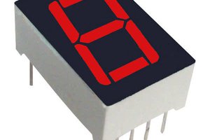
 Electroniclovers123
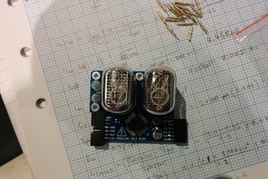
 Johnny
 Frederic L