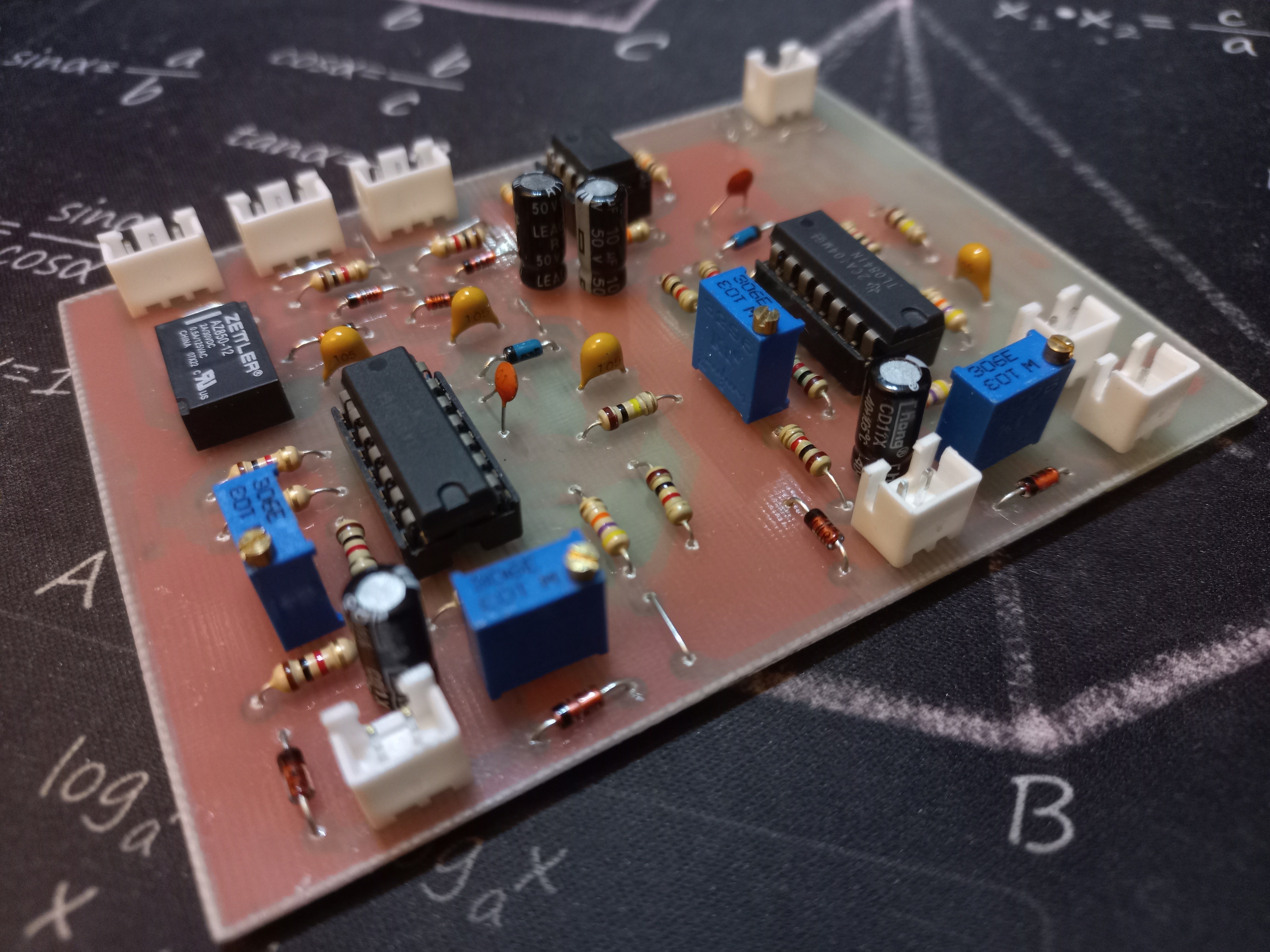
Close
0%
0%

VU Meter Deck

Measure audio levels with a retro analog VU meter driver!

Public Chat
Similar projects worth following
The goal of this project is to create simple yet accuarate analog driver for an analog VU meter. This device allows for measuring relative "loudness" of an audio signal. It's mostly aestetic because there aren't many use cases for such an audio minitoring device today but the driver delivers precise values and it acually can be used as a measuring intrument.

What does it do?

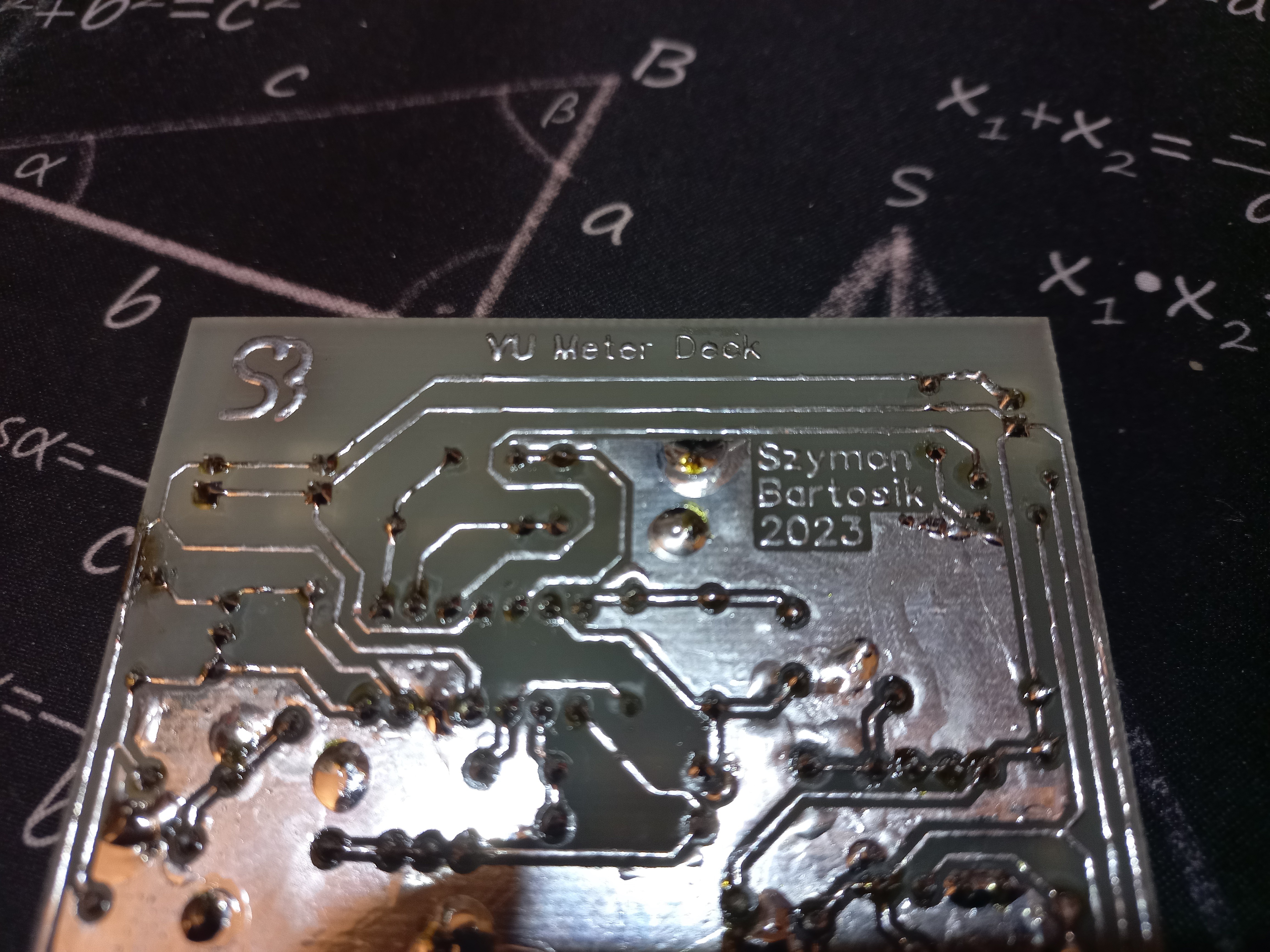
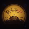
Analog VU meter is an voltmeter with a logarithmic scale in dB. It's used to see relative loudness of an audio signal so the volume of for example a microphone can be adjusted  in such a way that the loudness is contsant.

How to use it?

At first you have to define the loudness level of an audio source that you want to keep. Then the meter has to be calibrated using two potenciometers on the back in such a way that both gauges are at 0dB - that is your reference loudness level. After that the device shows in a logaritmic scale the "loudness" of an audio source that it reads comapared to the reference level - if it's in the red zone, it's too loud. Of cource this has many more use cases, if you signal is below 0dB it doesn't necessarly mean it's too quiet, it all depends what you are looking for.

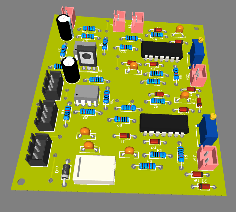
Simplified operation

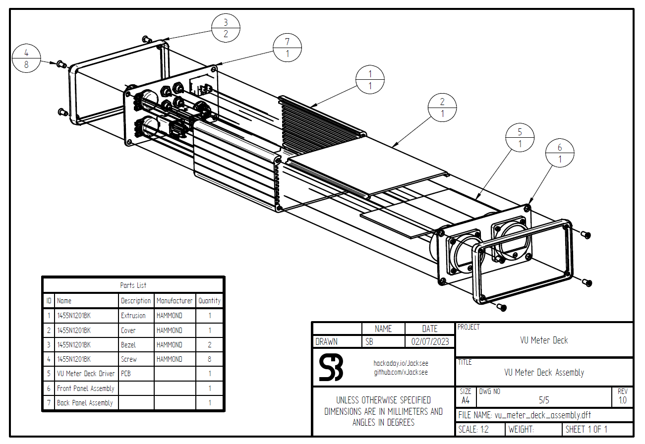
The meter cannot be used by it's own - it needs a driver. Such a driver has 3 tasks:

  • Amplify the signal for proper gauge operation,
  • Rectify,
  • Average the value (ideally with integration time of 300ms).

In practice it such a circuit has 3 main function blocks:

  • Amplifier,
  • Precision full wave rectifier,
  • RC averager.

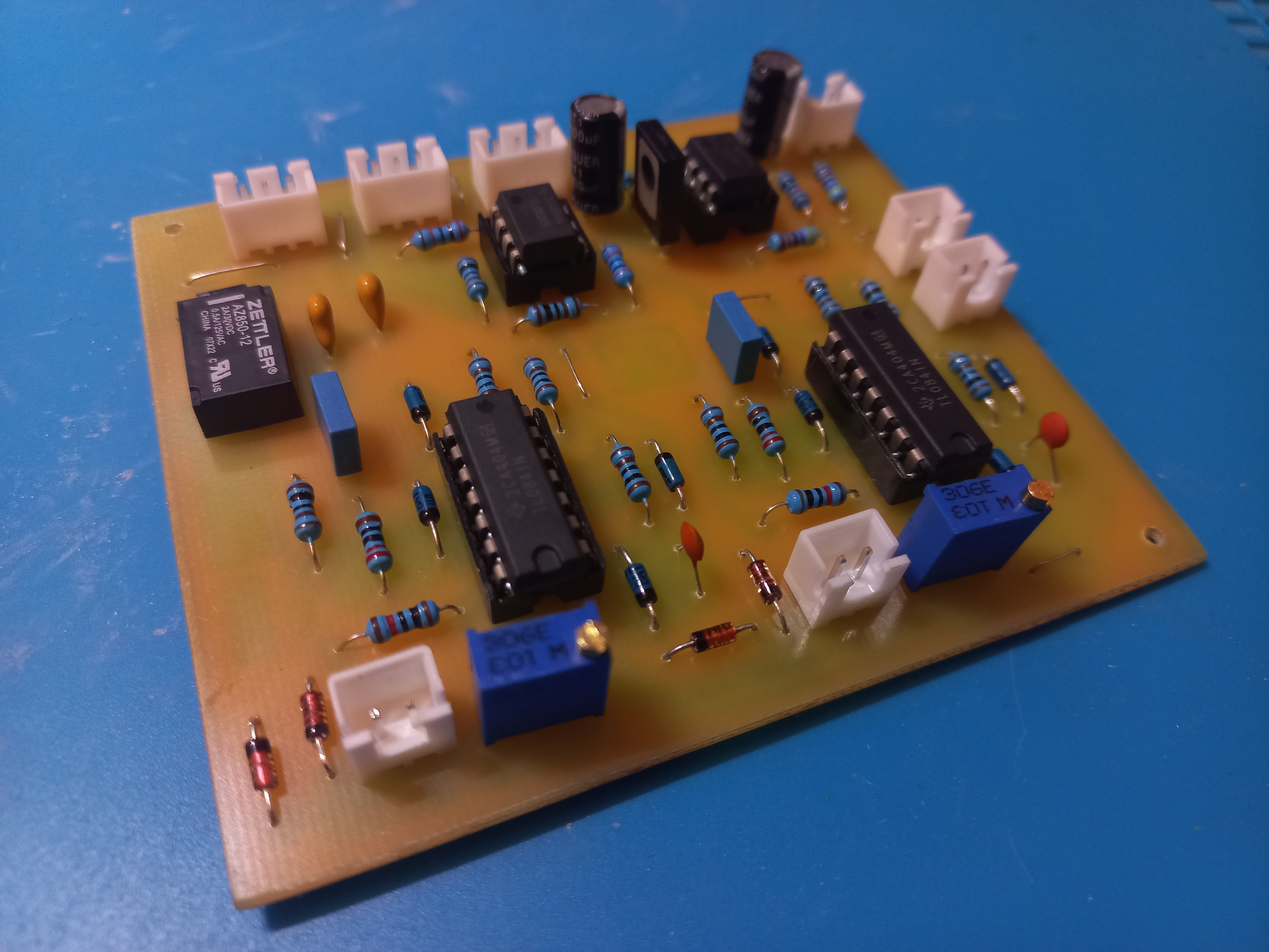
All of this is done with operational amplifiers. The main issue with building such a circuit is a frequency response. In an ideal scenario no matter if the signal has low or high frequency but the same amplitude the meter would always show the same reading. In reality op amps have limited slew rates and diodes used to rectify the signal have very steep non linear characteristics which introduces some error in the readings. The goal of making a good driver is to make amplitude - frequency characteristic of such instrument as flat as possible.

 
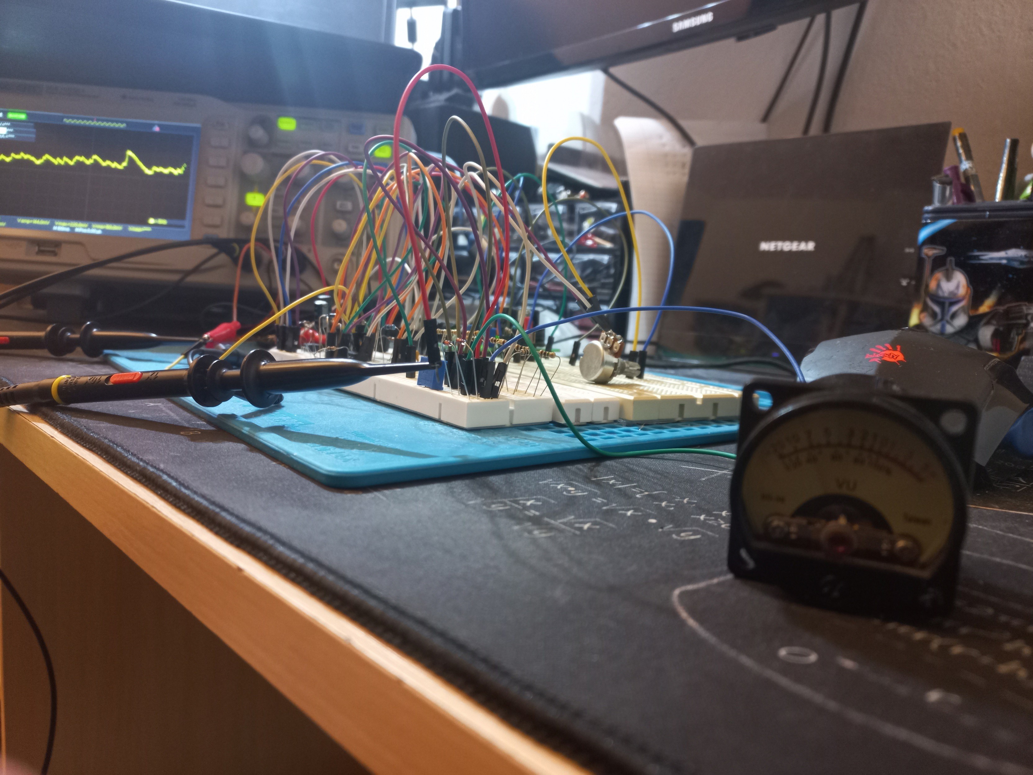
Normally the inertia of the gauge should average the rectifiet signal on it's own but because I've used random cheap gauges that certanly don't have proper balistics the driver is designed so that it can simulate gauges response on it's own by variable RC averager. Integration time can be changed via trymmers to a point that audio burst will change position of the needle for -20dB to 0dB in 300ms.


The driver also has external potentiometers for adjusting the correct reference level on the meteres.
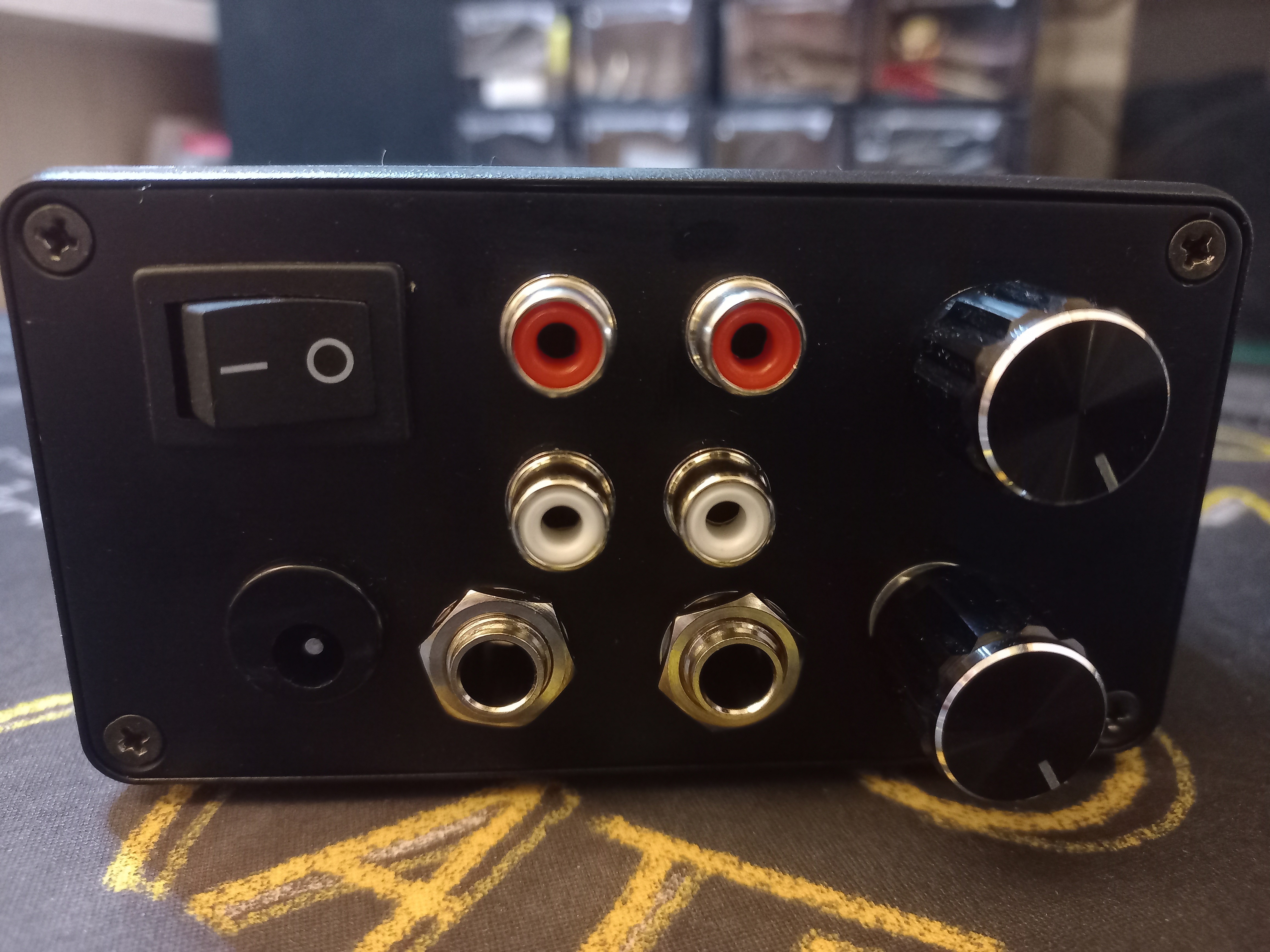
Features:

  • RCA input and pass-through port
  • 6,3 mm Jack input and pass-through port
  • 12 V DC 5,5/2,5 mm Jack power input
  • Relay audio disconnect on power-off
  • Left and right channel sensitivity potentiometers
  • Input overvoltage protection
  • Gauge overvoltage protection


JavaScript Object Notation (JSON) - 142.23 kB - 05/13/2023 at 20:04

Download

Adobe Portable Document Format - 120.71 kB - 05/13/2023 at 20:04

Preview
Download

JavaScript Object Notation (JSON) - 637.63 kB - 05/13/2023 at 20:03

Download

PCB_PCB_VU Meter Deck_2023-05-05.pdf

PCB template for etching

Adobe Portable Document Format - 183.68 kB - 05/13/2023 at 20:03

Preview
Download

Adobe Portable Document Format - 141.02 kB - 05/13/2023 at 20:03

Preview
Download

View all 6 files

  • 1 × TL082 DIP8 Amplifier and Linear ICs / Operational Amplifiers
  • 2 × TL084 DIP14 Amplifier and Linear ICs / Operational Amplifiers
  • 1 × BD140 TO-126 Discrete Semiconductors / Transistors, MOSFETs, FETs, IGBTs
  • 8 × BAT48 DO-35 Discrete Semiconductors / Diodes and Rectifiers
  • 4 × 1N4148 DO-41 Discrete Semiconductors / Diodes and Rectifiers

View all 34 components

  • #6 New updated PCB and schematic

    Szymon Bartosik05/13/2023 at 20:20 0 comments

    I've change schematixc quite a lot since last time and this should be the final version. Files are arleady uploaded. New board works great and it's very unversal - trymmers can be used to change the scale and also the integration time (needle delay) so now it can be used with different gauges.

  • #5 Assembled device

    Szymon Bartosik03/19/2023 at 22:23 0 comments

    The device has finnaly been assembled. Full documentation is going to be posted here some time in the near future.

  • #4 First prototype

    Szymon Bartosik03/19/2023 at 22:13 0 comments

    First board is ready and working!

  • #3 Final Testing

    Szymon Bartosik03/15/2023 at 21:07 0 comments

    Good news! Progess has been made, I tested the circuit with connected gauge and it works perfectly! I'm going to make the first PCB in a few days now so keep following.

  • #2 PCB layout is here!

    Szymon Bartosik03/08/2023 at 21:09 0 comments

    I've finished designing first version of PCB. It's all THT on single-sided board  (with some jumpers visible as top traces) for easy home fabrication. A little bit oldschool but if the prototype works there might be an SMD version in the future.

    For now I need to do the final testing and make my PCB.

  • #1 Schematic and prototype

    Szymon Bartosik03/05/2023 at 12:41 0 comments

    I'm currently finishing the schematic and the breadboard prototype works well. Making the PCB will take some time.

View all 6 project logs

Enjoy this project?

Share

Discussions

Isaac Wingfield wrote 03/07/2023 at 05:00 point

To be an actual VU meter rather than just a microammeter with a fancy scale, it has to have correctly specified acceleration and damping on the needle.

  Are you sure? yes | no

Dan Maloney wrote 03/06/2023 at 18:23 point

I've been wanting to add a physical VU meter to my setup, for recording the podcast. A real needle bouncing around is so much more satisfying than just using Audacity. 

I'll be following this one. Looking forward ti updates!

  Are you sure? yes | no

Szymon Bartosik wrote 03/06/2023 at 18:47 point

Thank you! It may take some time due to university but I'm planning to upload full documentation with frequency response graph.

  Are you sure? yes | no

Similar Projects

Does this project spark your interest?

Become a member to follow this project and never miss any updates