0%
0%
RGB macropad custom firmware
Custom firmware for the CH552 found in those USB RGB macropads with a rotaty knob
 biemster
Become a Hackaday.io member
Already have an account? Log in.
Just one more thing
To make the experience fit your profile, pick a username and tell us what interests you.
Pick an awesome username
hackaday.io/
Your profile's URL: hackaday.io/username. Max 25 alphanumeric characters.
Pick a few interests
Projects that share your interests
People that share your interests


 Kevin Osborn
 Albert Gonzalez
 Necromant
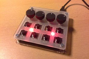
 Stefan Lochbrunner
hehe was just about to write a firmware but gave it another search and found this :D btw on linux you need to add some permissions first to access the bootloader. This should help those having issues:
echo 'SUBSYSTEM=="usb", ATTR{idVendor}=="4348", ATTR{idProduct}=="55e0", MODE="666"' | sudo tee /etc/udev/rules.d/99-ch55x.rules
sudo service udev restart
Thanks for making this firmware 👍