0%
0%
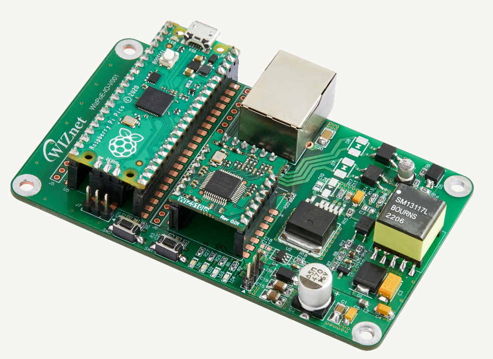
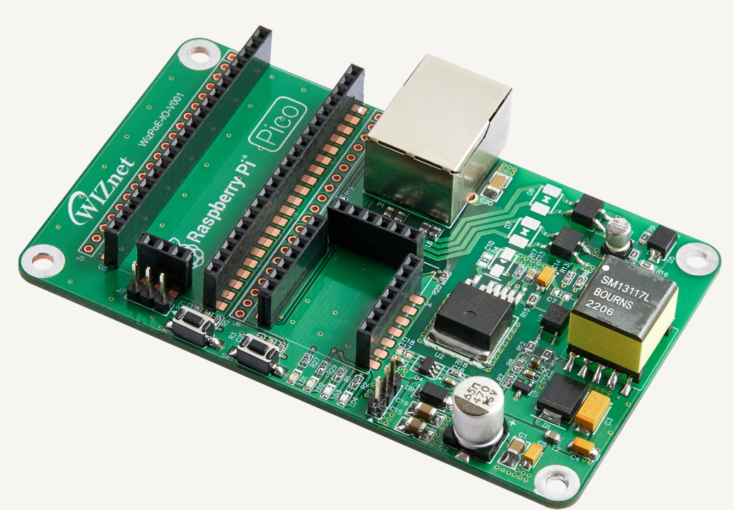
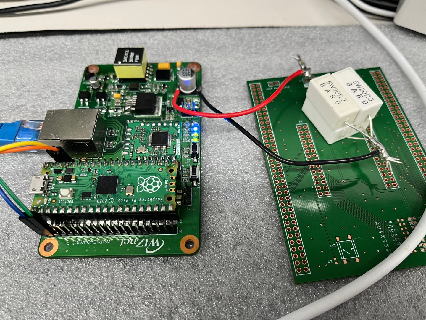
PoE + Pico + W5xxx-io Board Production Histo
[WIZnet] PoE + Pico + W5xxx-io board making process.
 Alan
AlanBecome a Hackaday.io member
Already have an account? Log in.
Just one more thing
To make the experience fit your profile, pick a username and tell us what interests you.
Pick an awesome username
hackaday.io/
Your profile's URL: hackaday.io/username. Max 25 alphanumeric characters.
Pick a few interests
Projects that share your interests
People that share your interests


 Torbjörn Lindholm
 Patrick Chwalek
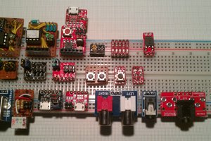
 Stefan Lochbrunner
 Jeremy Gilbert
Why did you only implement one side?