 Jerry Biehler
The biggest issue to getting this thing working has been the Electron Beam Gun power supply. This gun wants 10kv at up to 1.2amps to run it, thats 12KW! Not easy to do. I looked at trying to modify other stuff like ion pump power supplies, built voltage multipliers for lower voltage transformer to get the voltage, stack microwave oven transformers in series to get the voltage. Nothing sounded appealing. Ion pump supplies tend to top off around 6kv, multipliers for the kind of current I am looking at would need huge capacitors, and microwave oven transformers.... well, people have reported them working well in series when you isolate them but I just have a hard time believing I would be able to sustain the amount of current I need out of one.
Eventually on ebay a guy listed a couple of old Airco Temescal CV-14 chassis that had been parted out and mostly gutted. But the transformers were still there! He was in the sacramento area so I made a deal with him for $280 and drove down and picked them up. My poor Ford Ranger! These transformer are HEAVY! 305lbs each! Plus all the other stuff that came with it, the chassis themselves and all sorts of used parts from these machines. And most importantly, a bunch of the same type of relay that was used in the Flux Capacitor prop in Back to the Future. I can probably get $100 a piece for these so that should cover the trip alone.
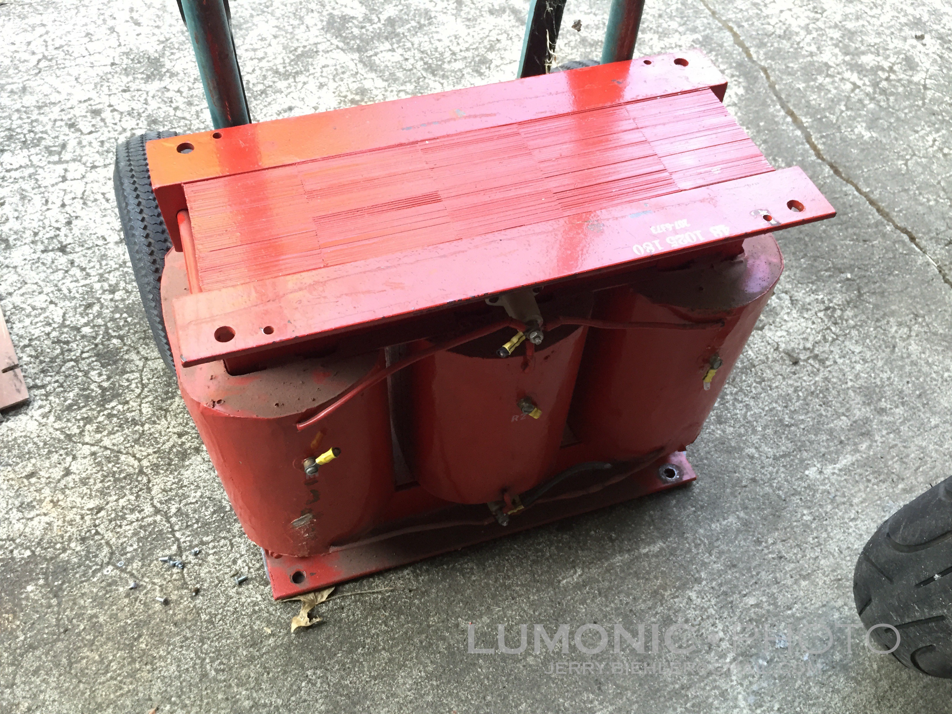
What a beast! Delta 208-240 3 phase in, Wye HV out with shielding between the primaries and secondaries. The idea is to drive the transformer from a Variable Frequency Drive, these devices are used to drive three phase motors at variable speeds by rectifying incoming power and then recreating the three phases with internal power transistors or IGBTs. Since they rectify the incoming line power they will often run on single phase so they are good options when you want to run a three phase machine tool at home.
So to test the theory. First thing to do was to rewire the chassis back to stock. Between all of the parts I had I had just about everything to put the HV DC section of the power supply back together. I found the schematics online which made things a whole lot easier.
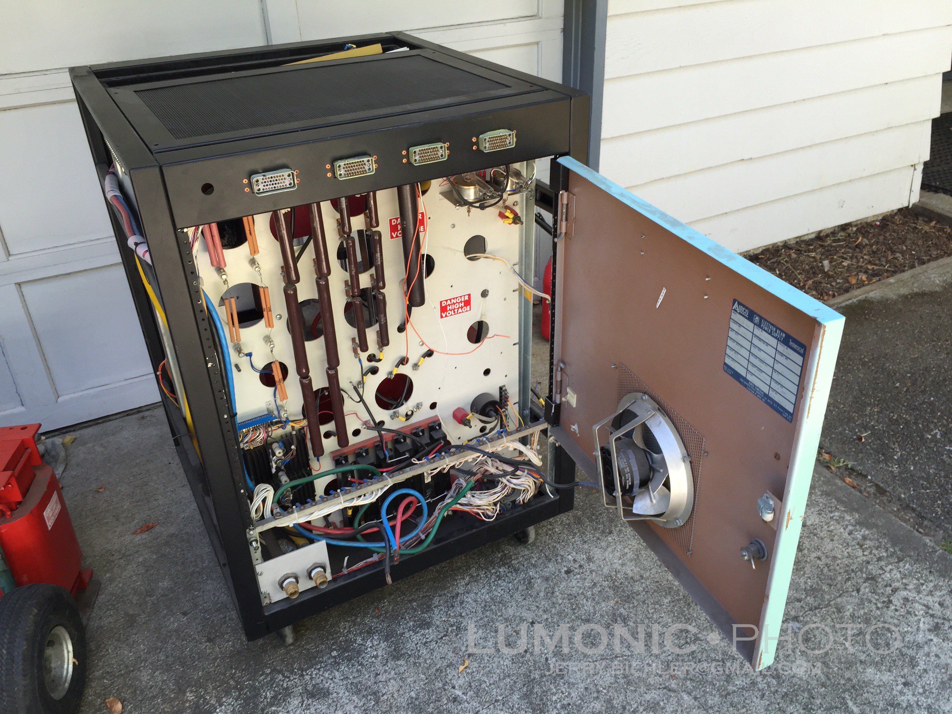
Once everything was rewired on that side I spliced in a 3HP Cerus Industrial VFD I had to the circuit breaker that feeds the HV transformer. I set it to V/HZ mode, no acceleration or deceleration, 240v out, and 60hz. I hooked a HV probe of a battery powered scope to the output terminals and hit the start button on the drive. It worked! Kinda, it was drawing a lot of current according to the internal ammeter on the VFD, something like 22A. Considering the drive is rated for 3HP, about 11 amps, it shut down pretty quickly. I increased the PWM frequency from 10khz to 15khz in the parameters and the transformer was much happier, only drawing 6 amps. It still shut down the drive after about 30 seconds but it was a good proof of concept test.
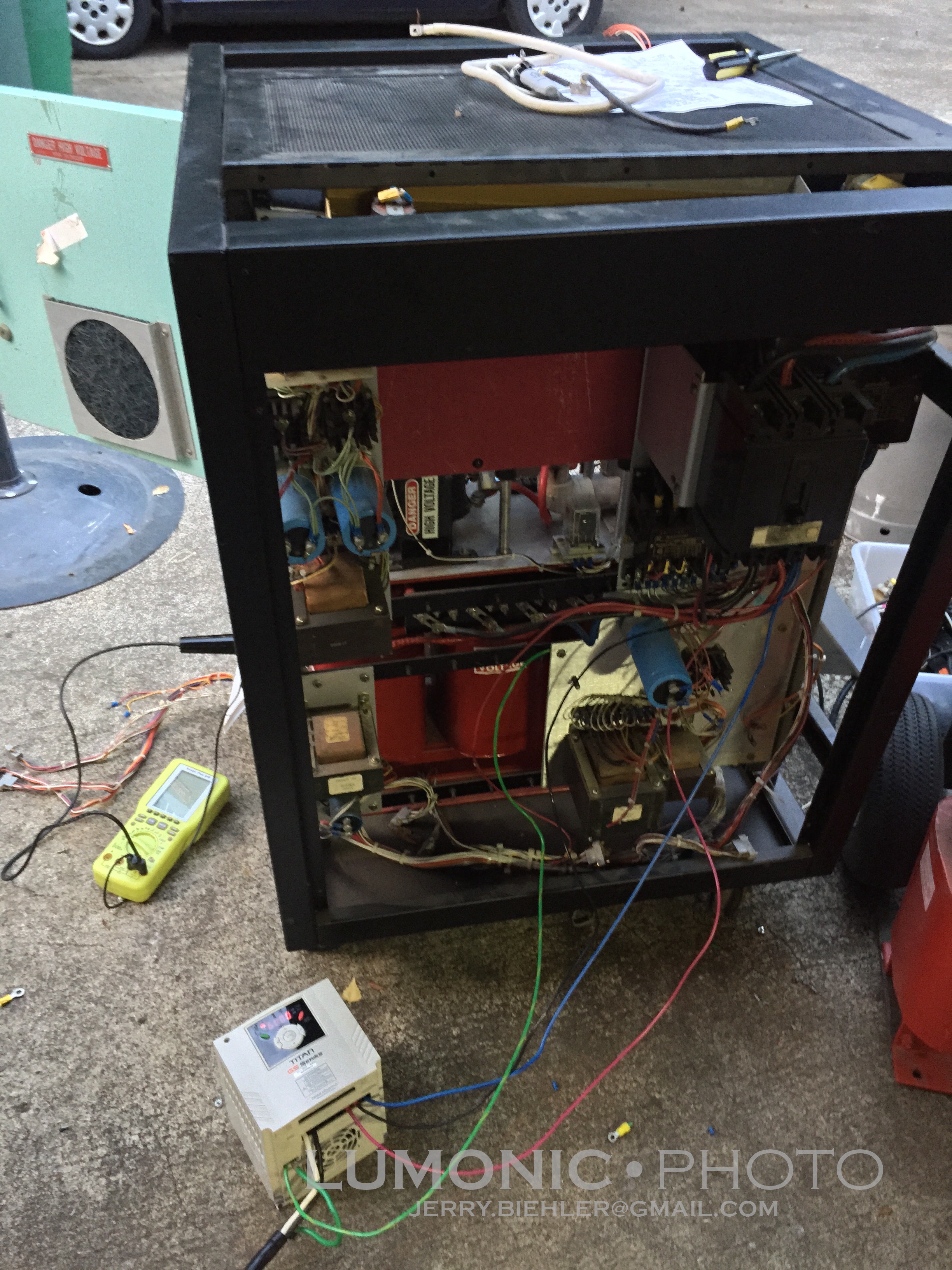
But I hit a problem. The most I could get out was 9.5kvdc. It was pretty stable at around +/-50v but thats with very little load. Once it gets loaded the voltage is almost certainly going to drop. In the original design the HVDC side came to 12.5kv after regulation. The positive leg ran into a water cooled triode, a Eimac 3CX20000A7, the 8KW sister version used a smaller air cooled 3CX10000A7. A pretty simple circuit drives the grid to regulate the voltage. The tube is gone but the base, filament transformer and the rest are there. So the thought was find a used tube to put back in there. Yeah... Easier said than done. Virtually nothing on ebay, what is there is around $1600. Ouch!
Another option was to build a cascode series of mosfets to replace the tube. I have a mass amount of them but the actually current handling capability at 1200v, what they are rated for, is pathetic so that idea died. Even if I did get it working I would have to figure out a drive for the filament transformer for the gun. Emission current of the electron beam is controlled through the temperature of the filament, the hotter it is the easier it is to emit electrons and the high beam current.
After all that I pretty much scrapped the idea of making one of these power supplies work. Instead I found another complete Thermionics 15kw power supply on ebay and the matching control box from another company. $500 for the power supply and $275 for the control box plus shipping which will probably run me about $2-250 on the power supply and about $50 for the control box. Ill figure out how to drive it later. I might just try to run it off a 15hp rotary phase converter I built years ago.
Now to figure out what to do with these transformers. Seems a waste to scrap them, I can rewire the primaries and make it single phase transformer. If I parallel the outputs I can get the full 10kv at 1.5 amps. I might be able to series the secondaries and get 30kv at 500ma! That would make one hell of a bug zapper! Actually these transformers scare the hell out of me....
One serious use might be to build a bombarding transformer for doing neon work, that is something I have always wanted to do. I would need a way to control the current out, it would be pretty easy to build a sliding core inductor to limit primary current. Another option would be to build a mag-amp for the output of the transformer.
So all in all, this part of the project has been a bit of a bust. I won't loose any money off it, in fact I will make some, and I did learn a VFD will drive a transformer without freaking out. I also may or may not have fried my HV probe, I dont know yet, it arced through the case seam to the chassis of the power supply.
Discussions
Become a Hackaday.io Member
Create an account to leave a comment. Already have an account? Log In.