 Just4Fun
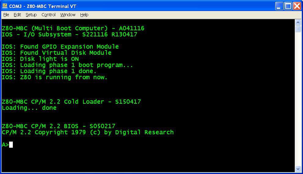
CP/M 2.2 quick set up guide
The set up is very simple. I've done an utility (iDisk) to simplify all the needed operations. Of course the Virtual Disk Module must be present, but you can have also only a "single disk" installed (but I recommend the original dual disk configuration), meaning that only U1 (see the A110417.pdf schematic) is populated.
The Assembler automated toolchain must be already set up.
Here all the steps:
- Update the IOS using the new file S221116_R130417_Z80.ino (or a newer version if present) in the File section;
- Reboot the Z80-MBC and select the iLoad boot mode (if not already selected);
- From the File section download the file "iDisk - S250317.hex" and copy it into your PC in the directory used for the Assembler automated toolchain . (Do not use the source file "iDisk - S250317.c" because it requires a special compiling option);
- From the File section download the file "CPM22_DualDiskPack.zip" and unzip it (for a single disk configuration download the file "CPM22_SingleDiskPack.zip"). Each disk image is divided into four .hex files called "segment" (32kB each) that are named accordingly (e.g. D0XXX_SEG1.hex means the segment 1 of disk 0);
- Upload the file "iDisk - S250317.hex" to the Z80-MBC using the Dos batch L.BAT (see Assembler automated toolchain) with the command:
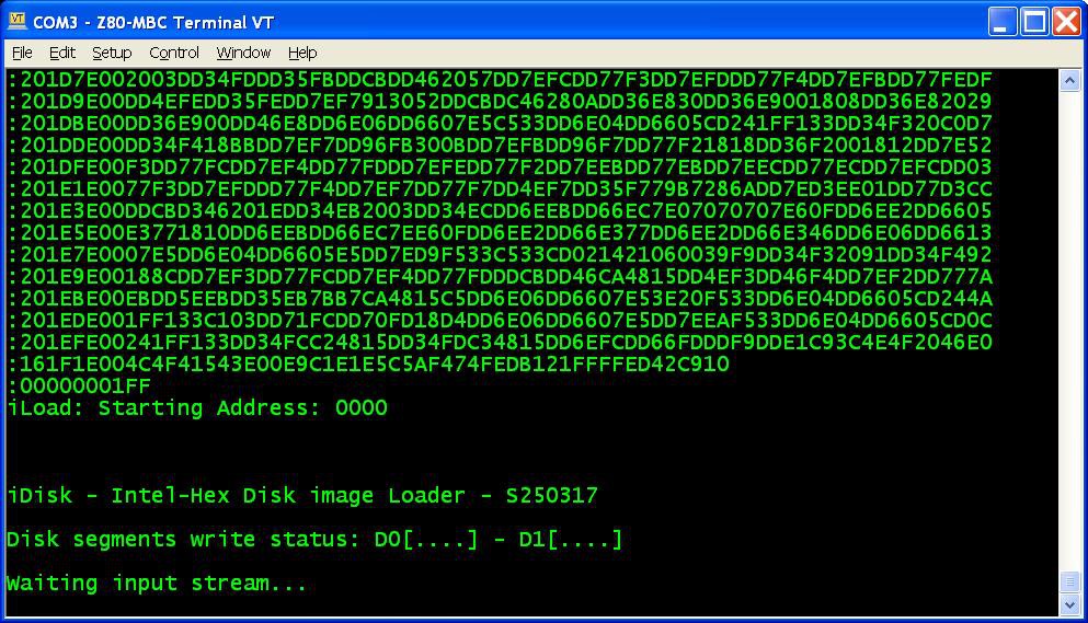
L "iDisk - S250317.hex" - When iDisk waits for the input stream:
![]() from the Tera Term menu select "File" -> "Send file..." and choice one of the unzipped .hex file from CPM22_DualDiskPack.zip (or CPM22_SingleDiskPack.zip for a single disk configuration). After the upload iDisk will show a summary:
from the Tera Term menu select "File" -> "Send file..." and choice one of the unzipped .hex file from CPM22_DualDiskPack.zip (or CPM22_SingleDiskPack.zip for a single disk configuration). After the upload iDisk will show a summary:![]() at this point press W to proceed and confirm your choice.
at this point press W to proceed and confirm your choice.
You don't have to follow any order in the "segments" upload sequence, iDisk will know how to do. To know before each upload what "segments" have been already written into the disks just see the "Disk segment write status":![]() in the photo the segments 0, 1 and 3 of Disk 1 have been already successfully written, so you can choose any of the remaining;
in the photo the segments 0, 1 and 3 of Disk 1 have been already successfully written, so you can choose any of the remaining; - Repeat step 6 for all the eight (or four for the single disk pack) "segment" files;
- Press the Reset button on the Z80-MBC and enter into the boot selection menu:
![]() select 4 for the CP/M loader (and select the disk light ON if not already done, to have an idea of the behavior).
select 4 for the CP/M loader (and select the disk light ON if not already done, to have an idea of the behavior).
 from the Tera Term menu select "File" -> "Send file..." and choice one of the unzipped .hex file from CPM22_DualDiskPack.zip (or CPM22_SingleDiskPack.zip for a single disk configuration). After the upload iDisk will show a summary:
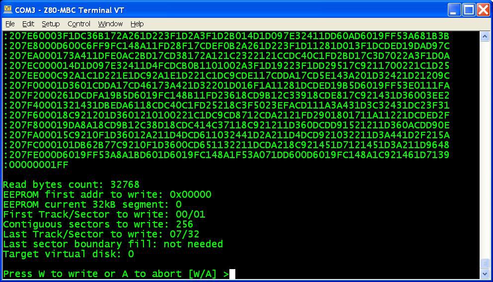 at this point press W to proceed and confirm your choice.
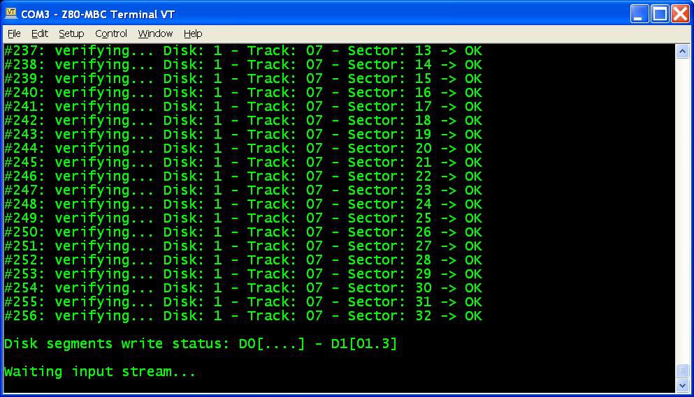 in the photo the segments 0, 1 and 3 of Disk 1 have been already successfully written, so you can choose any of the remaining;
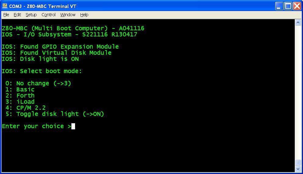 select 4 for the CP/M loader (and select the disk light ON if not already done, to have an idea of the behavior).
 All done!
NOTE: if you experience errors during the serial upload increase the delay after each line from the Tera Term menu (Setup -> Serial port -> Transmit delay -> msec/line). In my VM I set up a 90ms delay. This is due because Arduino serial port doesn't have any handshaking.
Disk speed
The Virtual Disk Module is based on simple EEPROMs using a 200KHz I2C serial bus. Of course do not expect the same speed of an hard disk with a DMA controller!
The speed probably is like using the floppy drive of those days...
Single disk configuration
You can have also only a "single disk" installed (but I recommend
the original dual disk configuration), meaning that only U1 (see the A110417.pdf schematic) is populated.
In this case you have about 120kB free, because the first two tracks of Disk 0 are reserved for the system image (Disk 1 doesn't have the system image, so all the 32 tracks are used for the file system).
Because the BIOS is the same and is configured for a dual disk system, if you try to select the "B:" drive you'll get a "BAD SECTOR" error.
Disk pack contents
In the disk 0 image there are the various external CP/M commands, the Basic interpreter, the CP/M Assembler and the Macro Assembler.
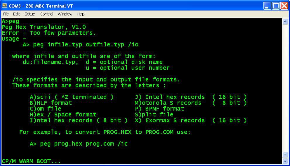
I've added also D, an alternative DIR command, and PEG, a bin to hex converter (and vice-versa) to exchange files:
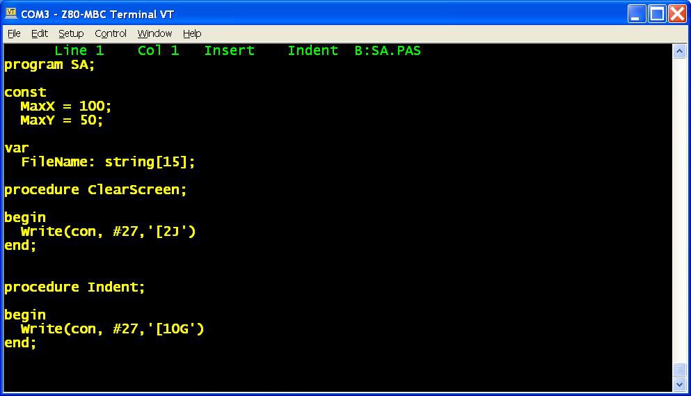
In the disk 1 image there is the complete Turbo Pascal compiler v3.01A with a sample program (SA.PAS):
 In the "single disk pack" the CP/M Assembler and the Macro Assembler are missing, and the Turbo Pascal is without the installing executable (not a big issue anyway) and without the sample program.
In a next Log I'll explain how create custom disk images.
Mind the .map!
During the development of iDisk I encountered "strange" errors during testing. After a while I noticed that these run-time errors seemed to be "sensible" to the code allocation, meaning that adding a single source line e.g., for a test print, caused a different run-time error. And all this without any error or warning from SDDC.
After some research I found that SDDC outputs a .map file with the linker allocation of the Code and the Data area, and with my surprise I saw that the SDDC Linker was allocating some variables OUT the 64kB address space!
After some tests it was clear the problem: the Linker by default puts the DATA section starting from the address $8000 (the second half of the 64kB address space). Because iDisk uses an array of 32KB (so the size is $8000 in hex), all the data space is used for it, and the Linker simply puts the other variables AFTER it, out the 64KB space! And without any warning.
So to solve the issue the solution was simply add in the command line of the SDDC invocation an option to set the DATA allocation at $6000 (--data-loc 0x6000)...
Conclusion: if you are using SDDC for something more complex than a "Hello world!" always give a look to the .map file!
The making...
I've never used CP/M, so the first step was to try to use it with a simulator just to have an idea, and read this book about the commands...
After some research I found that the real starting point was the CP/M Alteration Guide that explains how to write the BIOS that is the only part that interacts with the HW.
For the source I used that one on the Grant Searle site because already adapted for the TASM assembler. In the file "CPM22_BIOS - S050217.zip" (in the File section) there is the CP/M 2.2 source I used and the BIOS source I wrote/adapted for the Z80-MBC.
CP/M story

If you are pretty new to CP/M (like me), I suggest to read something about the story behind it. It is the story of ours PC.
Discussions
Become a Hackaday.io Member
Create an account to leave a comment. Already have an account? Log In.
Hello: I've returned back to see the progress you've made on this project. It looks great so far! You've spent a lot of time researching and creating. :)
In working with the iDisk program, besides setting the data-loc to 0x6000, what other sdcc options need to be specified in order to gain a successful compilation of the iDisk program? Should I assume that code-loc is 0x0100?
In running iDisk, I can't seem to get the disk images to load properly. After echoing the first line of the HEX file (:00000009F7), iDisk always aborts with the "ERROR: syntax error" message. Any ideas on what's causing this? I am running picocom on Linux.
Thank you.
Peace and blessings.
Are you sure? yes | no
Hi,
nice to "see" you again... :)
I suggest to use the provided ready-to-use .hex.
Anyway to compile see the comments at the beginning of the .c source (sdcc -mz80 --data-loc 0x6000 <input_source.c> -o <output_file.hex>)....
About the run-time error, you must add "some" delay at every end of line, because there isn't any handshaking on the serial (....NOTE: if you experience errors during the serial upload increase the delay after each line from the Tera Term menu (Setup -> Serial port -> Transmit delay -> msec/line). In my VM I set up a 90ms delay. This is due because Arduino serial port doesn't have any handshaking.....).
Follow exactly the instructions in this log... :)
Are you sure? yes | no
Hi:
I wanted to get back with some of the obstacles I had to overcome. First, I am not using the 24AA1025 parts for the Virtual Disk. I have samples of 24FC1026 instead. The difference is that 24FC1026 has no "A0" pin, only "A1" and "A2". Also, the "bank select" bit is in bit position 0 of the control byte, whereas on the 24AA1025, the "bank select" bit is in bit position 2 of the control byte. The 24FC1026 is more "software friendly" with the addressing and corresponding bit positions in the control byte. That said, a simple conditional statement took care of the differences in the two. For any one interested that may have access to the 24xx1026 parts, below are the changes required for the "S221116_R100218_Z80.ino" sketch.
Starting at line 106:
// ------------------------------------------------------------------------------
//
// Hardware definitions for A110417 (Virtual Disk Module)
//
// ------------------------------------------------------------------------------
#define EEPROM_TYPE 1026 // Define EEPROM type here (1025 or 1026)
// 24xx1025: A16 -> bit2 (0 0 0 0 0 A16 0 0)
// 24xx1026: A16 -> bit0 (0 0 0 0 0 0 0 A16)
#define EXT_EEPROM0 0x50 // I2C EEPROM 0 address (128kB)
#if EEPROM_TYPE == 1025
#define EXT_EEPROM1 0x51 // I2C EEPROM 1 address (128kB) (using A1 and A0)
#else
#define EXT_EEPROM1 0x52 // I2C EEPROM 1 address (128kB) (using A2 and A1)
#endif
----------------------
At line 1862 and 2109:
#if EEPROM_TYPE == 1025
blockSel = blockSel << 2; // A16 -> bit2 (0 0 0 0 0 A16 0 0)
#endif
-----------------------
I've been able to successfully test the 24FC1026 parts using the ViDiT utility and both 24FC1026's respond at the proper addresses for drive "A" and drive "B".
-------------------------------------------------------------
Now on to the remaining issue; I'm still having difficulty with loading the CP/M disk images. The same issue as I've mentioned before. Upon attempted uploading, iDisk aborts with "ERROR: syntax error Press ESC to continue..." with only the first line of the HEX file echoed (:00000009F7). Character delay is 2ms and line delay is 15ms. I've tried larger vaules up to 5ms character delay and 30ms line delay.
I've compiled with 'sdcc -mz80 --data-loc 0x6000 -o iDisk-S250317.ihx iDisk-S250317.c' but still the same error. I've used the HEX file you supplied but I still have the same error. I've configured picocom (under Linux) to strip outgoing CR's and again to strip outgoing LF's and neither corrects the issue.
At this point, I'm at a loss to comprehend the issue.
I'll try villaromba suggestion as well.
Any other suggestions?
Thank you.
Peace and blessings.
Are you sure? yes | no
Hmmm... try with a 100ms (or more) line delay. If the error is still present, try to "upload" manually (with the keyboard) from the terminal emulator to see where/if the error comes from the first line.
If I remember well, the CR at eol is required...
Are you sure? yes | no
Hi:
I found the problem. It was the iDisk code. Lines 108, 112 and 115 refer to the 'linefeed' character as being decimal 11 when it is actually decimal 10. I was able to correct the error when 'linefeed' was set to decimal 10 then reproduce the error again with 'line feed' set to decimal 11. The fix now works under Linux. With the code error, It works under WINDOWS with Teraterm and Realterm but I did not investigate why..
I added/modified the following lines:
Modified:
Line 108: if ((inChar != CR) || (inChar != LF)) putchar(inChar);
Line 109: else if (inChar == CR) {
Line 110: }
Line 111: putchar(CR); // CR + LF
Line 112: putchar(LF);
Line 115: } while ((inChar == CR) || (inChar == LF)); // Loop until a valid char is read
Added:
Line 25: #define LF 0x0A // Line Feed
Line 26: #define CR 0x0D // Carriage Return
On another note, I tested this on Linux using picocom. I was able to upload files with LF only (Linux & OSX) and CR/LF (WINDOWS) line endings. Character delay set to 1ms and line delay set to 10ms.
I also have some enhancements to submit for the AVR code that allows one to compile to interface with the 24xx1025 or 24xx1026 I2C EEPROMS, compile for 8 or 16MHz AVR clock options, 4 or 8 MHz Z80 clock options and I2C rates of up to 800KHz I2C the 24xx1025/1026 EEPROMs while maintaining I2C rates of up 400KHz for the GPIO and DS3231 modules. Even at AVR @ 8MHz and Z80 @ 4MHz, the 800KHZ I2C speed-up is noticeable. Of course, AVR @ 16MHz and Z80 @ 8MHz is really noticeable. :) How should I get the new code to you?
I'm not sure if this feature is referenced anywhere but note to users: The "magic" record submitted as the first line of all supplied CP/M disks is used to signify which "disk drive" the image belongs to. If there is no "magic record" on the first line (i.e. 'a standard INTEL hex file')), then a choice is given to enter the drive to use ('0' or '1').
The upgrade to using a 16MHz ATmega32/A AVR is fairly easy using Bill's V2.0 PCB. I used a 16MHz crystal in an HC/49U case glued upside-down to the the top of the PCB. I soldered two 22pf capacitors on the bottom of the PCB with their leads sticking through the "XIN" and "XOUT" holes that both terminate at the crystal. Be sure to update the AVR's bootloader to the 16MHz version of OptiBoot. With the new AVR host code, the Z80's clock can then me increased to 8MHz or left at 4MHz.
With Z80 running at 8MHz; I'm using an SRAM with a 120ns cycle time. Even at 8MHz, the shortest Z80's memory cycle time I measured was about 280ns (WR to RD), so the 120ns SRAM works fine. As a matter of fact, even 150ns SRAM's would work.
I had thought to increase the AVR's clock to 20MHz, which would yield a 10MHz or 5MHz clock for the Z80. I may still do it since its only two "free-floating" solder connections.
Great work! Thanks for sharing!
Peace and blessings.
Are you sure? yes | no
Wow! Really a great debug...
I'll send you a PM.
About the "Magic" record... yes, it's an "undocumented feature"... and you discovered that too... :)
PS: Have you tested if the "patched" iDisk version works in Windows using TeraTerm?
And tell me if the 20MHz hack works...
Are you sure? yes | no
Updated on 2018-0513
Hi:
First off, thanks for the invite. I'll upload the new IOS when I am finished with it.
I have another idea about using the two 24xx102x (128KB) EEPROMS as a single 256KB drive. The 'typical size' for 'typical' CP/M floppy disks was 256KB. It seems to me that I would rather have a single 256KB drive with the combined free space of both 128KB drives on a single 256KB drive. That's a function of the IOS, which will need to be able to support this feature. I don't plan to put a lot of hardware detection into the code to determine if there are two EEPROMs or not, that's the user's responsibility. Besides, the ATmega32A is getting rather full, with only about 2KB of code space left. I recognize that the CP/M disk parameter block would need to be modified to support 256 tracks instead of the current 128 tracks. There is also the possibility of migrating to the AT24CM02, which is a 2MB I2C EEPROM. It too is a 1Mb rate part. The internal addressing scheme is compatible with IOS with only slight modifications and that would get you two 256KB "drives". The only downside is that the AT24CM02 parts are SMD only and I've only seen them available directly from MICROCHIP. They are US$1.80 up to 25 pieces plus shipping.
On the increased I2C speed with the EEPROMs; I was only able to get them up to 800KHz rate. Although they are supposed to work up to 1MHz rate, they failed. The 24FC1026 datasheet says 2K for the I2C bus pull-ups if running at 1MHz, so I swapped ot R9 and R11 for 2K2 ohm and I still was unable to increase the rate to 1Mbps. Keep in mind that the increased rate (above 400K) only applies to the "FC" versions as the "AA" and "LC" versions are only spec's to 400KHz.
On your iDisk question; I tested it with picocom under Linux and with Teraterm under WINDOWS. No problems with either. :)
Because I am developing on Linux, I created a Makefile to ease things along. It was surprisingly difficult to locate any Makefile examples on the Internet using SDCC under Linux but I found one, which I heavily modified based on my own Makefiles from other projects I've worked on. With the Makefile, you can set the CODE and DATA locations and assemble the local "crt0.s" file or use SDCC's "replaced" crt0.rel file, which is how you have previously instructed folks on this forum. The Makefile is fairly project independent and will work with any of the Z80 'C' code you have supplied, including the ViDiT program. I will upload the iDisk and Makefile code soon.
On the 20MHz AVR clock; I originally had a 20MHz crystal wired to the AVR and running the Z80 at 10MHz but because I made several changes at that time, I was having some problems with iDisk and wanted to narrow the variables until I found the issue and corrected it. Technically, 20MHz @ 5 V is "out of spec" for the ATmega32A as the datasheet only shows a min CLK cycle time of 62.5ns, which is 16MHz. This is one reason why I switched back to the 16MHz AVR crystal. Eventually, I went back to the AVR internal 8MHz RC oscillator and ran the Z80 @ 4MHz to find the iDisk problem but now, I'm running the AVR @ 16MHz and the Z80 @ 8MHz.
Some weird stuff to ponder over; The AVR @ 20MHz was responsive but the Z80 @ 10MHz didn't seem to work and I have a 20MHz Z80 plugged into the socket. I have a 120ns access time 128KB SRAM, which should have worked but as stated, no joy on the Z80 @ 10MHz. Its possible that I have a flakey Z80, perhaps even a Chinese "fake" but I've not attempted to investigate further as I am satisfied with the AVR @ 16MHz, the Z80 @ 8MHz and the EEPROM's running at 800Kbps.
Another oddity (or not); before switching to the 20MHz Z80 (Z84C0020), the original Z80 I was using was a 4MHz version (Z84C0004) but I was able to overclock it at 8MHz without any apparent problems. I'm currently using the Z84C0004 (4MHz Z80) running at 8MHz.
Peace and blessings.
Are you sure? yes | no
Take in account that I'm "working" now on the new Z80-MBC2 that will make the Z80-MBC quite obsolete...
Are you sure? yes | no
See my repost above.
Are you sure? yes | no
Hmmm... I forgot to check on the Atmega32A datasheet... Yes, it's better to avoid the 20Mhz...
Are you sure? yes | no
Just4Fun:
Can you post the "utility code" you use to embed the Z80 code (uBIOS, etc.) into the IOS? That's the code that creates the data structures to be inserted into the IOS code. Update: Nevermind, I found 'xxd' for Linux. Using 'xxd -i [file.hex] dumps a 'C' structure.
I've posted the updated IOS sketch, the bugfixed iDisk and the Linux Makefile. I've also posted the OptiBoot loader for the ATmega32/A running at 16Mhz and 8MHz for those that need it.
And yes, I am aware that you are designing the MBC2. However, I am sure there are folks out there that have acquired PCB's for the 1st generation MBC that could use the updated code and information.
Peace and blessings.
Are you sure? yes | no
Tasm utility uploaded...
Are you sure? yes | no
Hi:
I wasn't able to get the program to do anything. It compiles without error but seems to not process anything. Probably a difference between WINDOWS and Linux file I/O.
If forgot that srec_cat can output "C" data structures. Under Linux also try:
> srec_cat S091216_R230117.bin -binary -o S091216_R230117.c -c_array -include
Also, under Linux there is 'xxd'. You'll need to pass it through SED or AWK to get the correct identifier:
> xxd -i S091216_R230117.bin | sed 's/unsigned char/const byte/g' | sed 's/\[\] = {/\[\] PROGMEM = {/g' > S091216_R230117.h
Peace and blessings.
Are you sure? yes | no
Awesome!! Thank you..... Had difficulties getting iDisk to successfully load despite increasing Tera Term timing. Found that by setting all sectors/data on VDs to &00 first iDisk always loaded successfully. Don't know why but it worked for me!!! CP/m on Disk 0 & 1 running perfectly - instructions great !!!
Are you sure? yes | no