 Bharbour
This board has an NXP PCF2127AT clock/calendar chip on it. The schematic shows an EEPROM chip (CAT24C256WI on it, but it is not populated in this project.
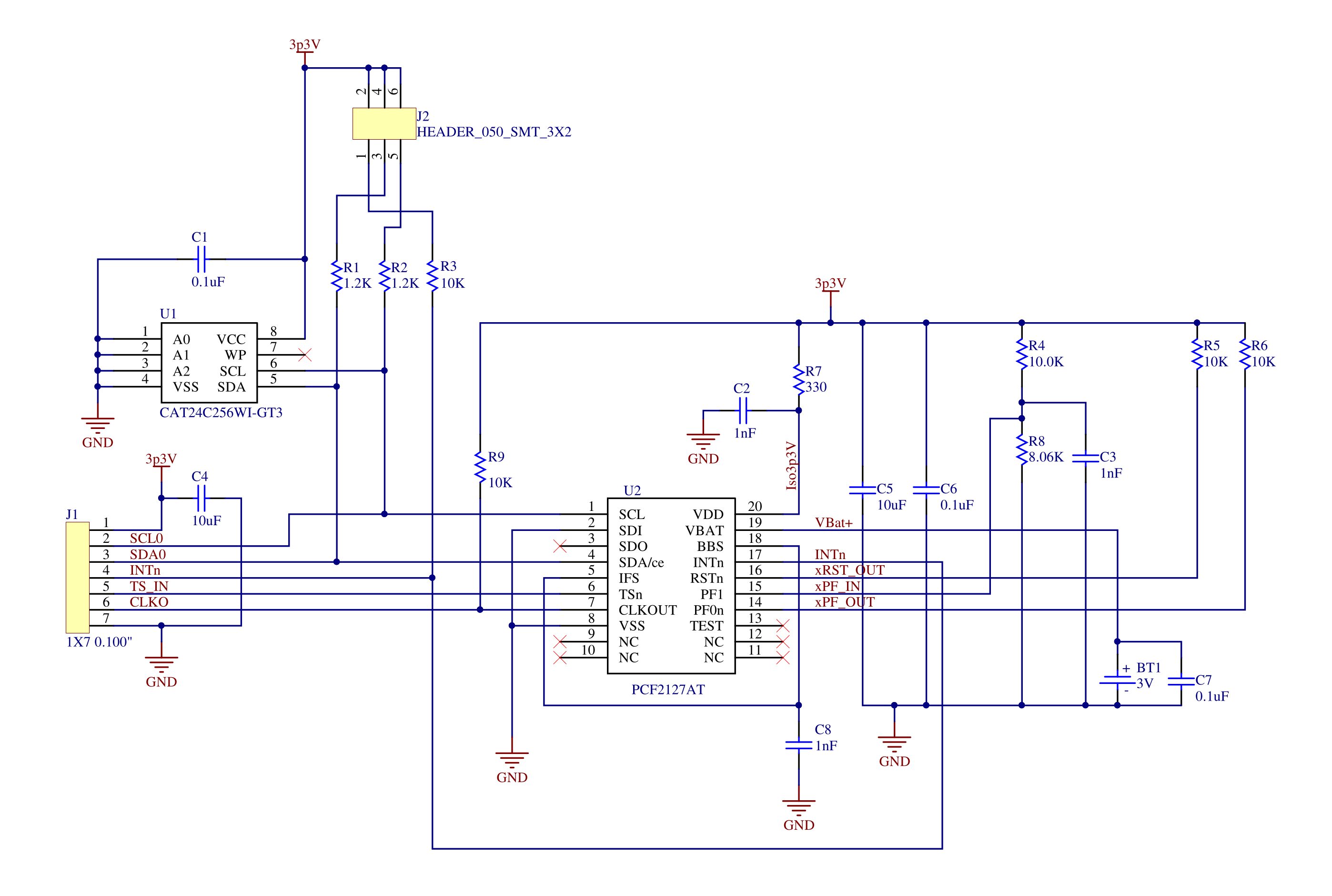
The PCF2127 chip can communicate via an I2C bus or a SPI interface. This board uses the I2C interface. An interrupt signal (INTn) from the clock chip is used to signal the processor that the seconds value has changed, which means that you don't need to poll the chip over the I2C bus continuously. The interrupt signal is routed to a GPIO input on the processor where it is polled in the main loop. It is trivial to get the GPIO input data register, fetching the contents of an on-board hardware register compared to conducting a couple of I2C bus transactions. Reading the GPIO data register takes less than 100nS, while reading the clock register and resetting the internal address pointer takes about 200uS.
There is a small amount of RAM (512 bytes) in the chip which can be used to store non-volatile data. Clock operation and maintaining the RAM contents while the system power is off is done with a CR2023 battery. The switching between system power and battery power is done inside the chip.
The chip has provisions for accepting a signal for time stamping. This could be used to discipline the clock from a GPS receiver or something similar, but this system is not using that capability.
I have used this chip in several other projects, and the timekeeping is very accurate, good to a minute or less per year.
Discussions
Become a Hackaday.io Member
Create an account to leave a comment. Already have an account? Log In.