 Kevin Santo Cappuccio
Turns out, digital compasses are a bitch, doubly so in vehicles. The earth's magnetic field is tiny, especially compared to all the stray electromagnetism a car spits out with reckless abandon.
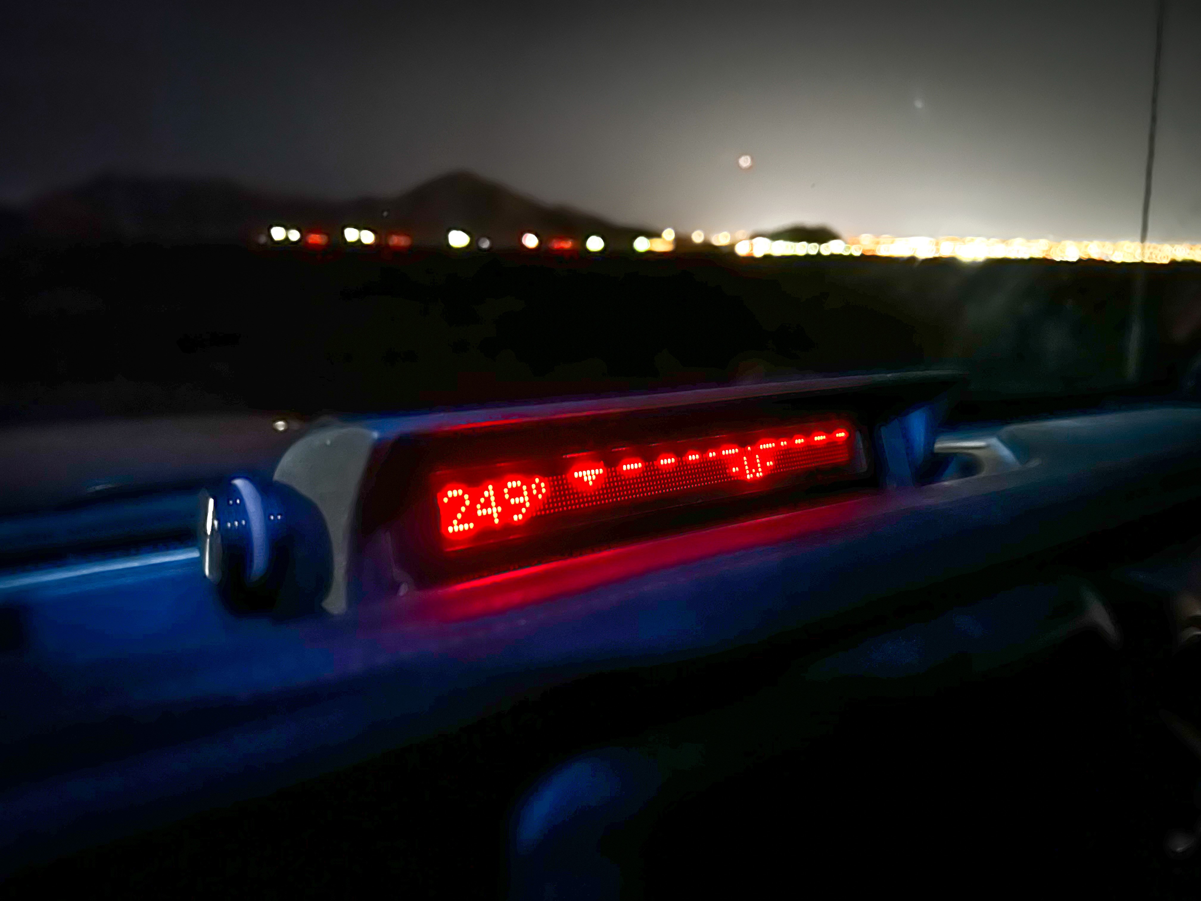
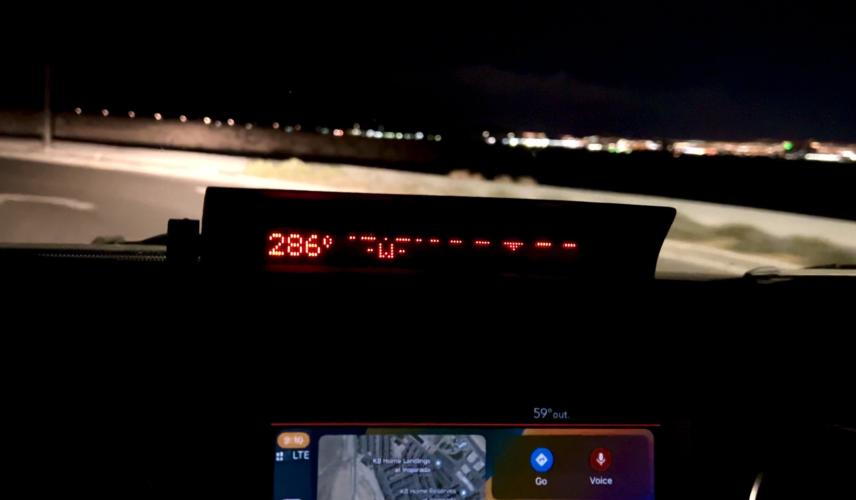
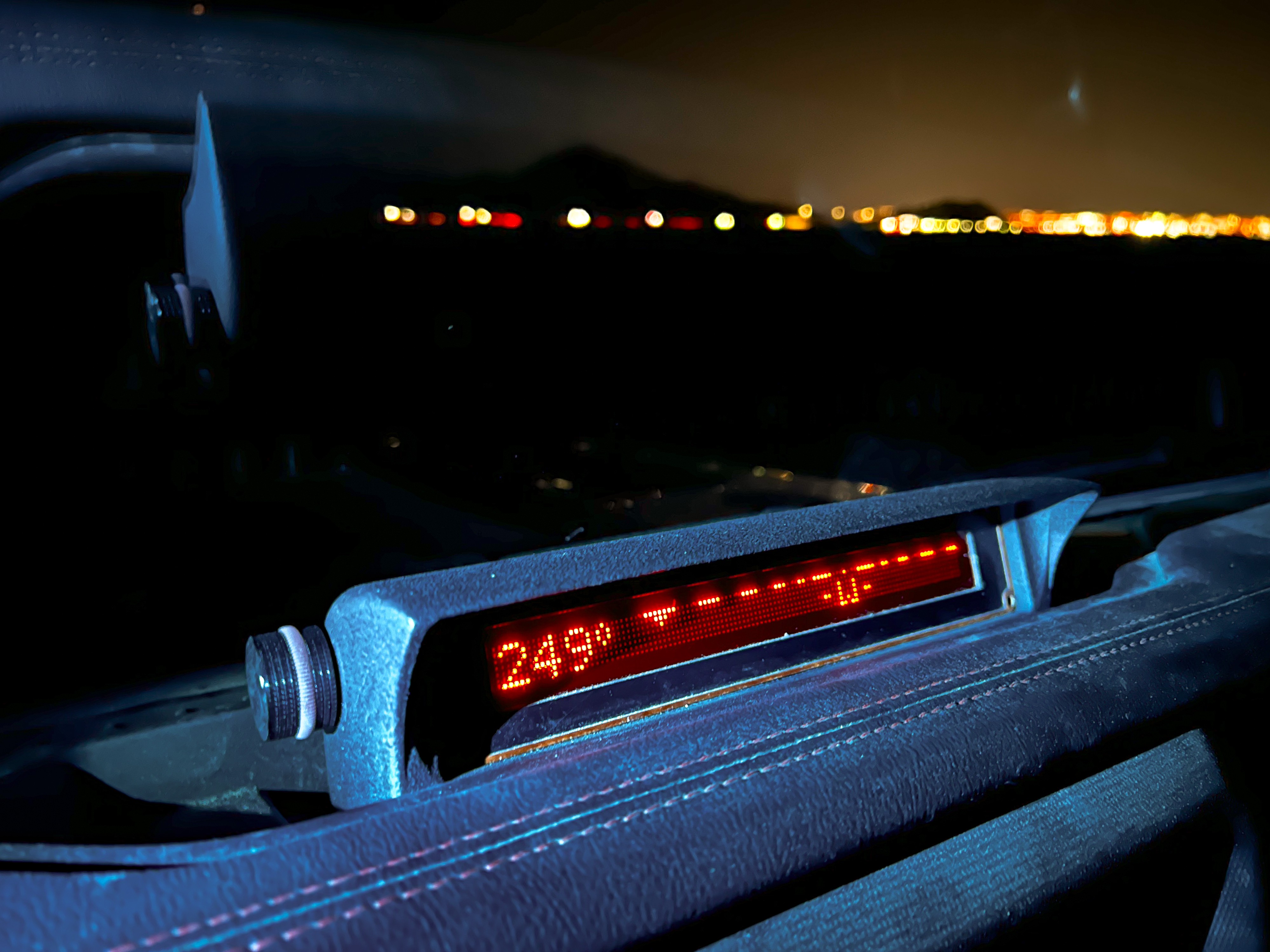
(There really aren't many things to show pictures of for this, so instead I'm just going to separate parts with some glamorous night shots of the compass. So if this all seems complicated, the photos might remind you that it was all worth it.)
When I first installed the compass module on my dashboard, instead of showing me the direction of north, it showed me the direction of my alternator. It could be useful if you live in a place where people regularly steal alternators out of cars, but that wasn't what I was going for.
So I had to find a way to both calibrate the compass to correct for all that "hard iron" and ideally get it as far away from any metal or electrical current as possible.
Luckily, I drive a Jeep Wrangler with a hard top made out of fiberglass. So I can stick an IMU reasonably far away from any metal. I'm talking to the sensor via I2C, which is only supposed to travel less than a foot or so. And I needed about 9 feet of wire to get the IMU to the best spot in my car furthest from things the magnetometer would consider "bullshit." Instead of converting to a longer distance protocol and then converting back, I used an Adafruit LTC4311 I2C Extender / Active Terminator. This thing just watches the I2C lines and if it sees a rise in voltage, it clicks on a much beefier MOSFET to help the lines get to the level they were trying to get to. It works great (but also note that it only works up to a 400KHz I2C clock, the 1MHz clock speed might work sometimes but might be unreliable.)
The cable is just 5 strands of wire wrap wire twisted together with a power drill and a few inches of heat shrink every couple feet. I did this to keep it thin enough to shove it under the plastic moulding in my car without having to remove it. Taking that stuff off without damaging it is such a pain.
Originally I was using an MPU-9250 9 DOF IMU, the microcontroller would get the sensor readings form the gyroscope, magnetometer, and accelerometer over I2C and then apply a Mahony Filter (similar to a Kalman Filter) to convert those raw readings into a heading.
The problem was, those kinds of filters need to be constantly fed new data and recalculated at around 400-2000Hz to be remotely accurate. Which would be totally fine if that's all the microcontroller was doing, but I'm also running a display that is timing sensitive as well.
The real bottleneck was I2C, the STM32L432KC runs at 80MHz and has a hardware floating point unit, so it could do the math more than fast enough. More annoying is that the I2C read times aren't consistent, sometimes it would take like 400 uSec which was longer than the hold time for a column on an IGV1-16, so I would end up with these moving stripes of brighter pixels where the reads took longer (how long you hold on each column determines the brightness of the display, to a point.)

Eventually I searched for a better solution and came upon Pesky Products' USFSMAX Module. What's cool about this thing is that it has a MAX32660 microcontroller onboard that gathers all the data from the IMUs and does all the math continuously so the heading stays accurate even if the main microcontroller isn't asking it for data.
The way they programmed the MCU as a kind of virtual EEPROM makes dealing with it exactly like reading data form any other I2C thing. Just send it an address and it responds with the contents of that register.
Here are repositories for that give a ton of information about this particular module and sensor fusion in general.
Example sketches for the USFSMAX module
A rundown of all you'd ever want to know about motion sensing
Another cool thing this module has that is an absolute must if it's going to be mounted in a car is the ability to choose between 3D and 2D Dynamic Hard Iron correction. Soft and Hard Iron correction is done to cancel out the effects of metal around the magnetometer.
Shawn Hymel has a page explaining what that is while looking super slick in his bowtie
But you'll notice in all these calibrations, the magnetometer needs to be spun around in all axes, and since this needs to be done in it's final mounting place, you'd need to be doing some crazy monster truck rally shit in your car to get a calibration. The 2D Hard Iron offset allows you to calibrate your compass in only the axis that is easily achievable in a car.

In case you're curious what the "dynamic" means, I am too. My best guess is that it comes from the fact that instead of taking readings for a set amount of time to get a calibration, it just keeps going until it gets an acceptable reading.
This caused me a lot of trouble thinking it wasn't working. Because I was just testing and didn't care if the calibration was accurate, I wasn't moving the module thinking it would just give me a shitty calibration. But it never did. So keep that in mind if you're using one of these.
But eventually I got it calibrated, I tested by printing out a compass rose and making sure each 90 degree turn was actually 90 degrees.
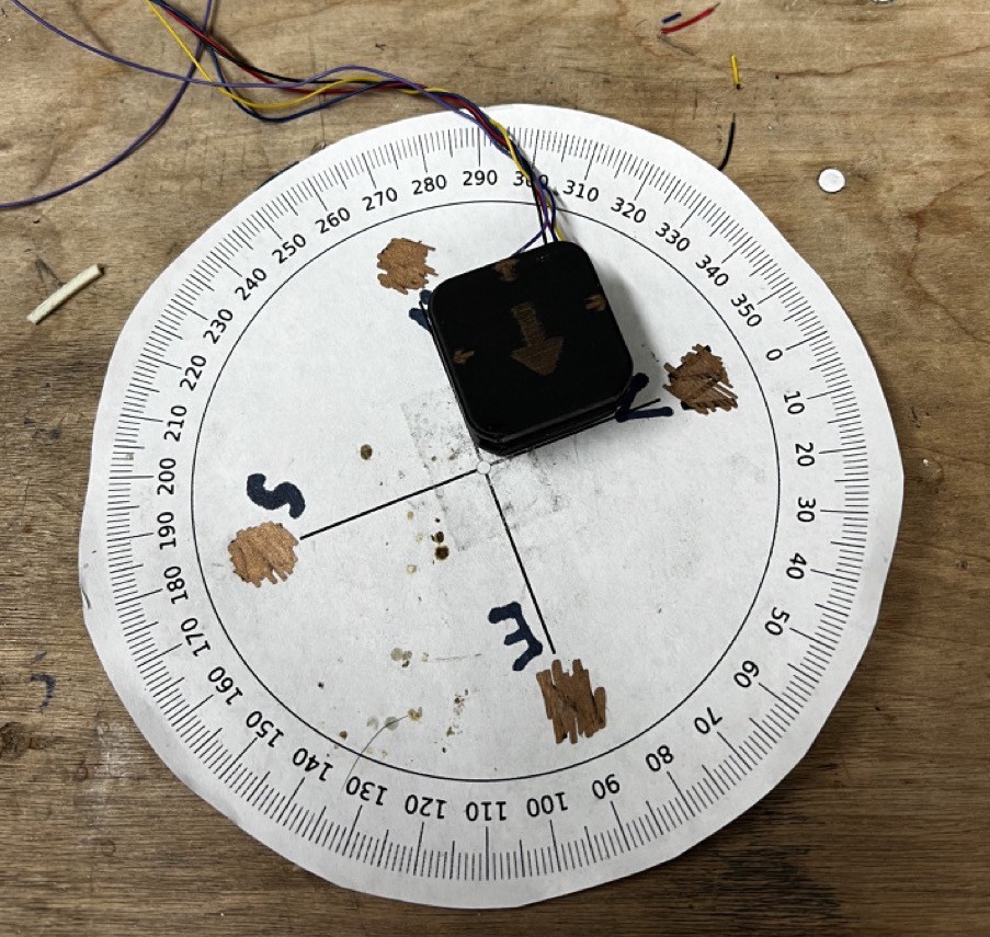
Notice the scratched out cardinal directions, some psycho made a compass rose and uploaded it to the internet with the wrong headings.
Putting it in a little square 3D printed thing helped a lot to line up with the directions exactly and get an idea of accuracy.
After 5 straight days of pulling my hair out trying to get an accurate compass heading, I had finally succeeded! Woo!
Now onto the enclosure and putting everything together.
Discussions
Become a Hackaday.io Member
Create an account to leave a comment. Already have an account? Log In.