 Matthias Koch
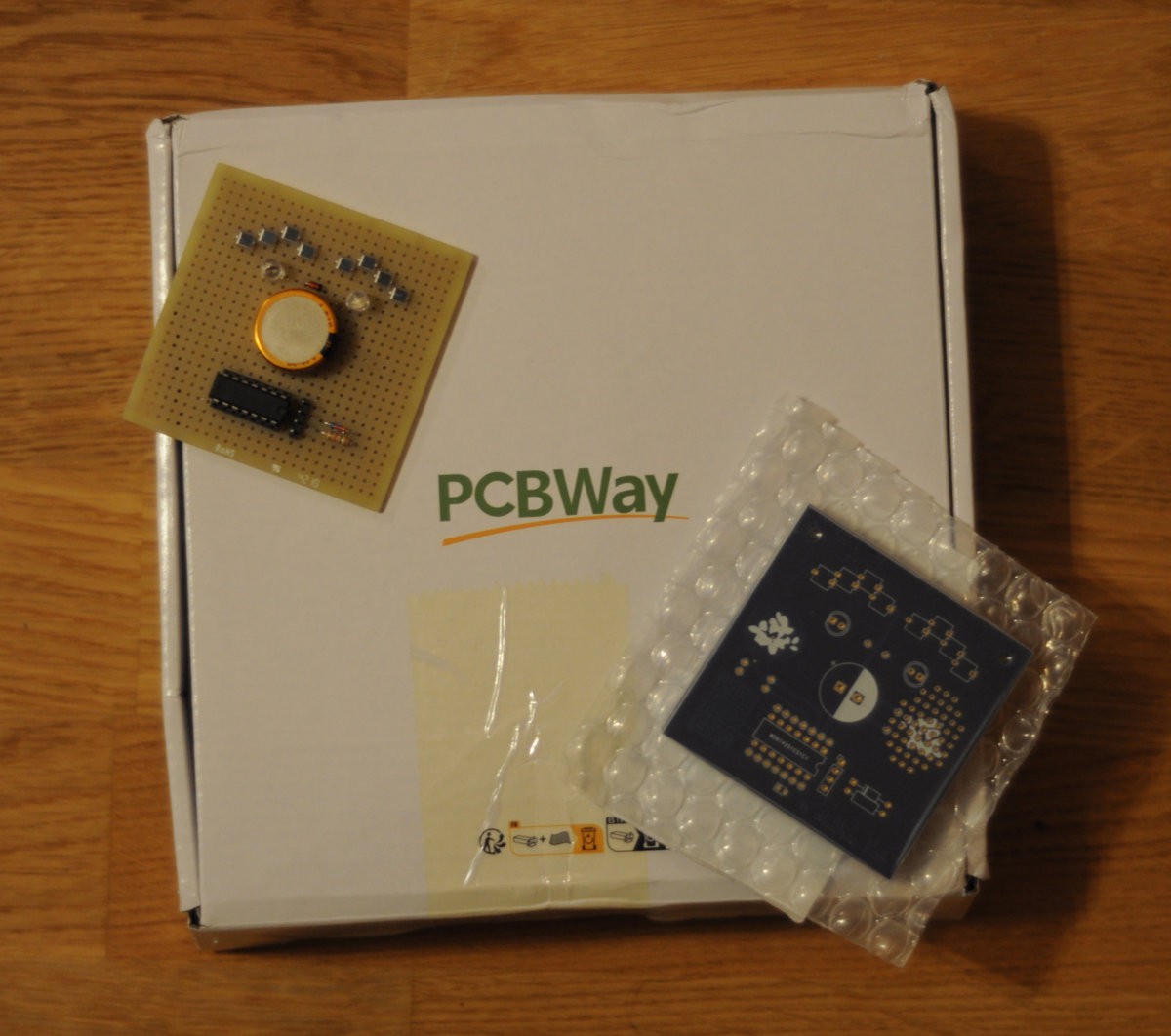
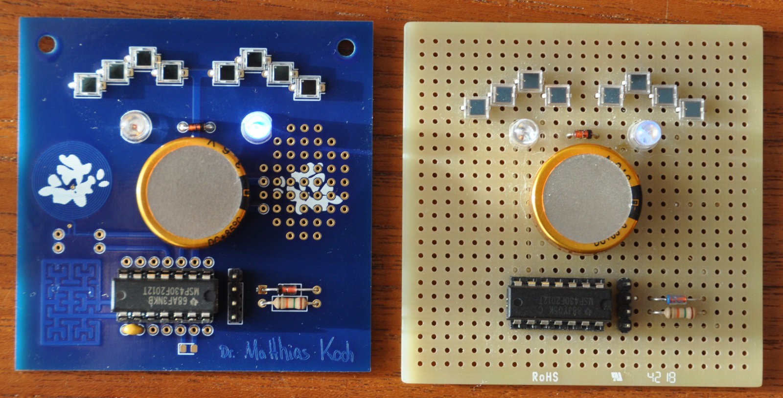
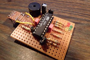
"Greenhouse Blinky" is a blinky that gets charged even in dim light using BPW34 photodiodes, and runs a MSP430F2012 microcontroller from a large capacitor.
Schematic in ASCII art:
   Eight BPW34 photodiodes in series
  A C  A C  A C  A C  A C  A C  A C  A C
/-|>|--|>|--|>|--|>|--|>|--|>|--|>|--|>|-\
|                                        |
|                                    + - |
|      BAT85 Schottky Diode          | | |    1.5F 3.6V
o---------|>]----------------------o-| |-o   Memory backup capacitor
|        A   C                     | | | |   (low self-discharge)
|                                  |     |
|                            Anode o-|>|-o Cathode  Blue LED as shunt regulator
|                                  |     |
|                                 [o o o o]  Four pin programming header
|                                  | | | |
|                            Vcc   1 | | 14  Vss
|                            P1.0  2 | | 13  P2.6
|                            P1.1  3 | | 12  P2.7
|                            P1.2  4 | \-11  TEST
\----------------------------P1.3  5 \---10  /RST--[15kOhm]-->Vcc  Reset pullup
   Red LED Anode     /-------P1.4  6      9  P1.7
   Red LED Cathode   \--|>|--P1.5  7      8  P1.6
                                 MSP430F2012
Eight BPW34 photodiodes in series provide the voltage even in dim light to charge the memory backup capacitor, which was selected because of its low self-discharge current. The generated voltage is fed directly to pin P1.3 of the MSP430F2012 which is set as input, and due to internal protection diodes on the GPIO pins the microcontroller can charge the capacitor. For improved low light performance and to reduce current through the protection diode on very high light levels, a BAT85 schottky diode was added which bypasses the internal protection diode of the input pin with its lower forward voltage.
The firmware is written in Forth, and can be cross-compiled using current Mecrisp-Across:
new

\ <><><><><><><><><><><><><><><><><><><><><><><><><><><><><><><><><><><><><><>
    TARGET
\ <><><><><><><><><><><><><><><><><><><><><><><><><><><><><><><><><><><><><><>

\ ----------------------------------------------------------------------------
\  Timer interrupt handler flashes LED
\ ----------------------------------------------------------------------------

: impulse ( -- )
  16 p1out cbis!
  16 p1out cbic!
;

\ ----------------------------------------------------------------------------
\  Hello World
\ ----------------------------------------------------------------------------

: blinky ( -- )

  \ Pin & Clock initialisation

  \ Disable crystal oscillator, set P2.6 and P2.7 as low outputs
  0 p2sel c! 0 p2out c! %11000000 p2dir c!

  \ No special functions, set P1.3 input, all others low outputs
  0 p1sel c! 0 p1out c! %11110111 p1dir c!

          0 DCOCTL  c!
          0 BCSCTL1 c!
  %00001000 BCSCTL2 c!  \ SELS: VLO --> SMCLK
  %00100000 BCSCTL3 c!   \ LFXT1S VLO, 12 kHz --> SMCLK, ACLK

  \ Timer initialisation

   $10  TACCTL0 !  \ CCIE
 12000  TACCR0  !   \ VLO/12 / 1000 = 12 kHz / 12 / 1000 = 1 Hz
  $110  TACTL   !    \ ACLK, Up Mode

  begin
    lpm3
  again
;

\ <><><><><><><><><><><><><><><><><><><><><><><><><><><><><><><><><><><><><><>
    HOST
\ <><><><><><><><><><><><><><><><><><><><><><><><><><><><><><><><><><><><><><>

$FFF2 vector impulse \ Timer A0
$FFFE vector blinky   \ Reset vector

crosscompile

disimage-file helloworld.asm
 hexdump-file helloworld.hex

bye
Pins are configured, with all unused pins set to low outputs in order to avoid floating inputs.
P1.3 is left as input, to accept charge, and could be used to measure the voltage generated by the photodiodes at the moment. The internal analog-digital converter could be used to compare the capacitor voltage (the ADC internally allows a Vcc/2 measurement relative to internal 2.5V or 1.5V bandgap references) and the photodiode chain voltage relative to VCC to determine if the capacitor is currently charging or not. Also there is a temperature sensor available to be read with the ADC in the MSP430F2012.
The red LED is connected with both anode and cathode to the microcontroller, as this allows for brightness measurements (see LEDs as photodiodes and Which colours are LEDs sensitive to ? for details).
These advanced features are not yet in use in this simple blinky "Hello World", the code instead serves as a testbed of the lowpower configuration of the microcontroller:
An internal ~12 kHz oscillator (VLO,...
Read more »


 hkdcsf
 Klaus Dormann
 Jose Ignacio Romero