J. M. Hopkins
-
Interfacing the TLC5940
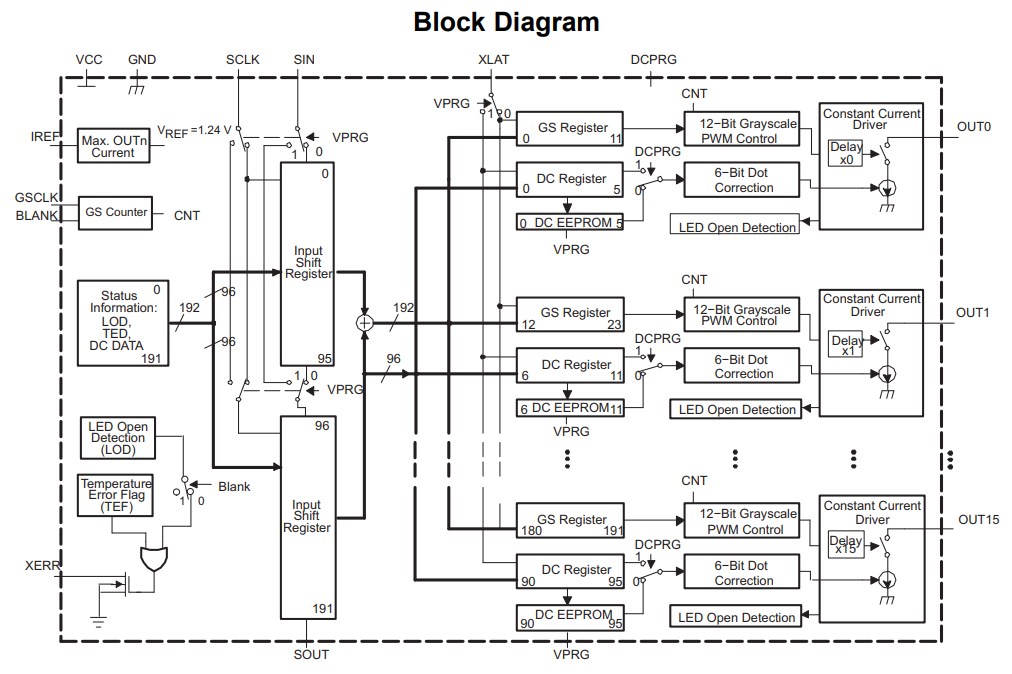
03/24/2023 at 13:39 • 0 commentsThe TLC5940 is an IC from Texas Instruments for controlling 16 PWM channels of LED control. It will interface with the Teensy and provide the button power and PWM signals.
While the block diagram is a bit busy, it's pretty easy to interface with the Teensy. Requiring just 5 signal wires, with 2 additional wires running with resistors to set IC states.
The logic for controlling the TLC5940 will be via the PJRC TLC5940 Library (github), which will make controlling the LEDs in the buttons super easy.
#include "Tlc5940.h"

void setup() {
    Tlc.init();
}

void loop() {
  Tlc.clear();
  Tlc.set(0, 4095); //channel 0-15, value 0-4095
  Tlc.update();
}
Using this library, setting up fading effects and variable brightness for button states will be easy.
-
VCA - SSI2164
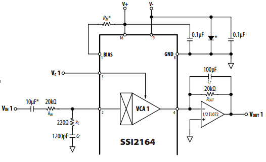
03/24/2023 at 11:42 • 0 commentsThe Sound Semiconductor SSI2164 quad vca chip was selected to be used as the mute VCA. Typical Application from the datasheet looks like this:
In essence, we convert the incoming voltage to a current through the 220 Ohm / 1200pF RC Network (the VCA is current based), we control this via Vc1, which is a -33mV/dB exponential voltage input which is capable of +20 to -100dB gain with -660mV to 3.3V.
Since we are utilizing this as a +0dB to -100dB VCA we can avoid the need for negative voltage and only require the 0V to 3.3V input, which due to the IC's nominal impedance of 10kOhm with an internal 10:1 divider we can run directly from the Teensy's digital output pins (0-3.3V).
Coming out of the VCA, we put it through a 0dB buffer stage with the TL072 and out the jacks.
-
Buttons and LEDs
03/23/2023 at 16:47 • 0 comments![]()
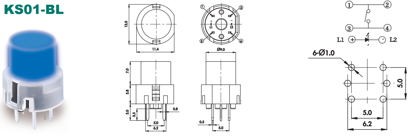
The KS01-BLV-2 is a SPST-NO switch with built in LED (Color is Yellow to match the Sinfonion). This project will be treating it as two different systems, the momentary press normally open switch and the LED indicator.
The switch itself will feed directly into the microcontroller, and the LED will be driven by the TLC59401 (we'll talk about this specific interface in a future project log). The TLC59401 will allow for each of the 14 button LEDs to be PWM driven, to allow for dimming of the LEDs and more advanced display options (while saving on pin counts)
![]()
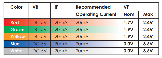
The nominal LED current is 20mA with a 1.9V voltage drop. Powering it from 5V from the PWM signal of the TLC59401 will require dropping 3.1V at 20mA, or ~155 Ohms, and in reality it'll be will probably drive with a 220 Ohm 10% resistor.
Buttons will be read by feeding the 3.3V through the momentary press switch, while enabling the Teensy's native PULLDOWN resistor on the channel. Debouncing of the signal will occur on the microcontroller as well.
See the TLC5940 interfacing projects log for more details on actually driving these LEDs. -
Modes and Buttons
03/18/2023 at 14:48 • 0 commentsOverview of the Modes
- Edit Mode
- Any changes to the current step's value is saved into the step sequencer
- Add will add a step, shifting the rest of the sequence right and incrementing length
- Delete will delete the current step, shifting the rest of the sequence left and decrementing length
- Pressing Edit/Live will change mode to 'Live' mode
- Live Mode
- Changes made to the current step will NOT be saved at clock/step+/step-/reset
- Pressing Add/UMO will change mode to 'Live Unmute Override' mode
- Pressing Del/MO will change mode to 'Live Mute Override' mode
- Pressing Edit/Live will change mode to 'Edit' mode
- Live Unmute Override
- When pressing the tracks buttons, will turn on unmute overrides for those tracks, these overrides will not be changed by the step sequencer
- Pressing Edit/Live will change mode to 'Edit' mode
- Pressing Add/UMO will change mode to 'Live' mode
- Pressing Del/MO will change mode to 'Live Mute Override' mode
- Live Mute Override
- When pressing the tracks buttons, will turn on mute overrides for those tracks, these overrides will not be changed by the step sequencer
- Pressing Edit/Live will change mode to 'Edit' mode
- Pressing Add/UMO will change mode to 'Live Unmute Override' mode
- Pressing Del/MO will change mode to 'Live' mode
General Button Behavior
- Track button LEDs will show the current step's mute status
- Pressing a track button will toggle the current value and the LED that indicates its value
- Step+ and Step- buttons
- Normally not illuminated
- Will illuminate at 50% for 100ms on receiving a pulse on the clock jack input
- When pressed, will change LED brightness to 100% until released
- When pressed, will display current step on the track buttons until released
- if 8 or less steps, will display in '8-up' mode at 50% brightness
- if more than 8, will display in binary mode at 50% brightness
- Add/UMO and Delete/MO buttons
- Normally not illuminated
- When pressed, will change LED brightness to 100% until released
- In Live mode, will latch to 50% brightness when UMO and MO modes are active
- In Edit mode
- Will shift all steps right one from current step, and keep the current step the same value
- This essentially 'copies' the current state, at step+1, and shifts the other steps +1
- In Live Mode
- transitions to UMO/MO modes
- Edit/Live Button
- Normally not illuminated
- On Press toggles between Edit and Live mode
- When pressed
- LED goes to 100% brightness, until released
- on release either latches off (edit mode) or 50% (live modes)
- Reset Button
- Normally not illuminated
- Will illuminate at 50% for 100ms when receiving reset pulse on the reset jack input
- When pressed
- LED goes to 100% brightness until released
- Sets current step to 0
- Disables clock in when pressed
- Edit Mode
-
Data Structure and General Modes
03/18/2023 at 14:45 • 0 commentsMain Sequencer Variables
The Mute Sequencer is an 8 track step sequencer, storing boolean values for the mute status. The maximum sequence length is 255 steps with 8 tracks containing the mute values. Length is the current sequence length (minimum 1, max 255) and step is the current step number. So if you look at sequencer[3][TRACK_1] you'd get the boolean value for Track 1 at step 3.
boolean[255][8] sequencer[step][track]
byte            length
byte            step
To not get confused on the boolean value for mute/unmute, we also #define their values. And because tracks are 1 indexed physically, and 0 indexed logically we'll also add in #defines for them too. These will also double as their button numbers.
#define MUTE    false
#define UNMUTE  true

#define TRACK_1   0
#define TRACK_2_  1
#define TRACK_3   2
#define TRACK_4   3
#define TRACK_5   4
#define TRACK_6   5
#define TRACK_7   6
#define TRACK_8   7
Buttons have a few arrays to allow debounce and have state change flags for rising edge / falling edge logic.
boolean[14] button_current_state[button]
boolean[14] button_last_poll[button]
boolean[14] button_changed[button]
LEDs are a bit simpler, as they are just an array, but because we're controlling LED intensity as well, they are actually byte arrays for 0-255:
byte[14] led[button]And adding a few more defines for the rest of the buttons and modes. (Mode is the general state machine state, of which we have 4)
#define BUT_STEP_PLUS   8
#define BUT_STEP_MINUS  9
#define BUT_ADD_UMO     10
#define BUT_DEL_MO      11
#define BUT_LIVE_EDIT   12
#define BUT_RESET    13
#define BUTTON_DEBOUNCE_TIME 50

#define MODE_EDIT     0
#define MODE_LIVE     1
#define MODE_LIVE_UMO 2
#define MODE_LIVE_MO  3
Modes and general button behavior in the in next log...
-
Module Layout
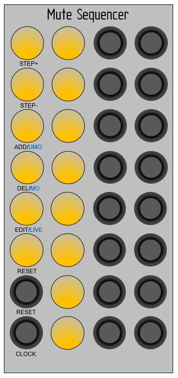
03/18/2023 at 11:38 • 0 commentsSo overall layout will be similar to the following image (quickly rendered in Power Point):
![]()
8 tracks are lined up vertically, controls are on the first column, track mutes / display on second column, inputs on third, and outputs on fourth.
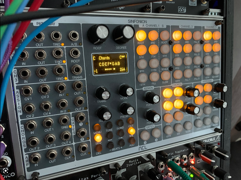
Note that the push buttons are momentary push, and can be illuminated by separate control logic. The idea is to pair with the ACL Sinfonion, not exactly, but in spirit. You can see buttons with full and partial illumination here for an idea of functionality:![]()
-
Concept of Operation
03/17/2023 at 22:04 • 0 commentsThis module will be in Eurorack format with the following specifics:
- This device will be 10-12hp
- 10 x 3.5mm mono inputs (8 track inputs, 1 clock, 1 reset)
- 8 x 3.5mm mono outputs
- 14 momentary LED lit pushbuttons
- Same part number / color as the ACL Sinfonion circle push buttons
Connections:
- 8 track inputs
- 8 track outputs
- 8 buttons of track mutes
- Step+, Step-, Add, Delete, Edit/Live, and Reset buttons
- Clock and Reset gate inputs
Logic:
- Microcontroller + VCAs + Opamp buffers
User Interface
- The Track Button LEDs will show current mute status of the track (8 total)
- clock in will increment the step sequencer
- reset in will reset the step sequencer
- Sequences can be 255 steps long
- Edit/Live Modes
- Edit Mode
- whenever a track button is pressed, it is immediately saved into the current step
- Live Mode
- a track button will change the mute status for active step only, and is not saved
- override modes allow for muting/unmuting channels regardless of step sequencer values
- Edit Mode
- When changing steps, length, and such, display current step/length on the track buttons as a display
- more on this as we get code structure sorted later
Rough Initial Parts List
- Buttons: KS01-BLV-2 https://www.tme.eu/en/details/ks01-bl-2/keypad-switches/highly/ks01-blv-2/
- 16 channel LED IC: TLC5940
- VCA: SSI2164
- OpAmp: TL074