 thpoll
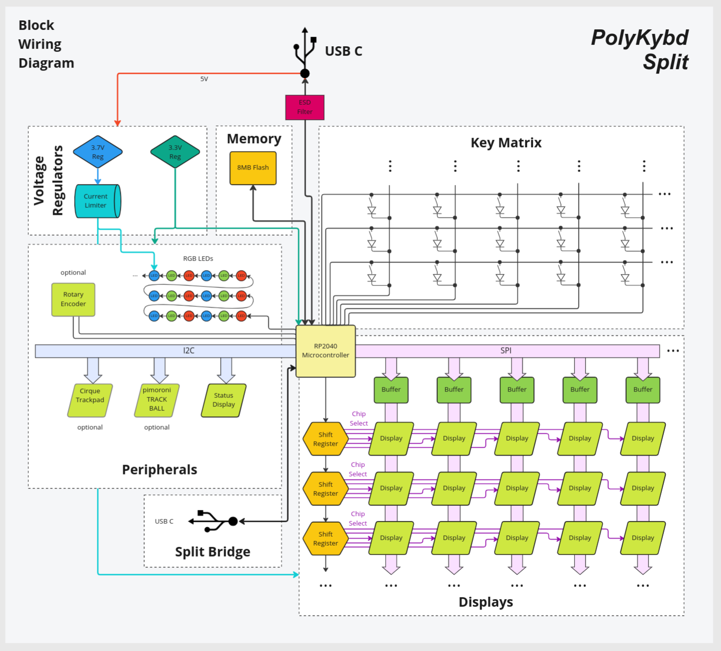
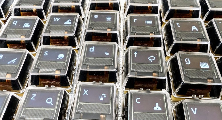
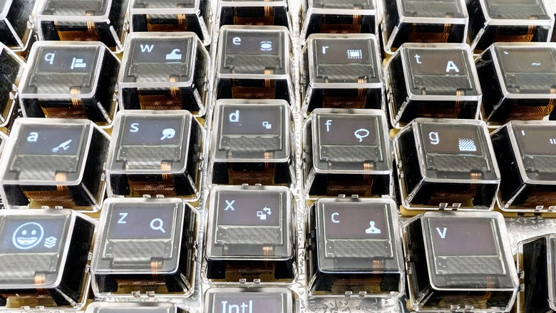
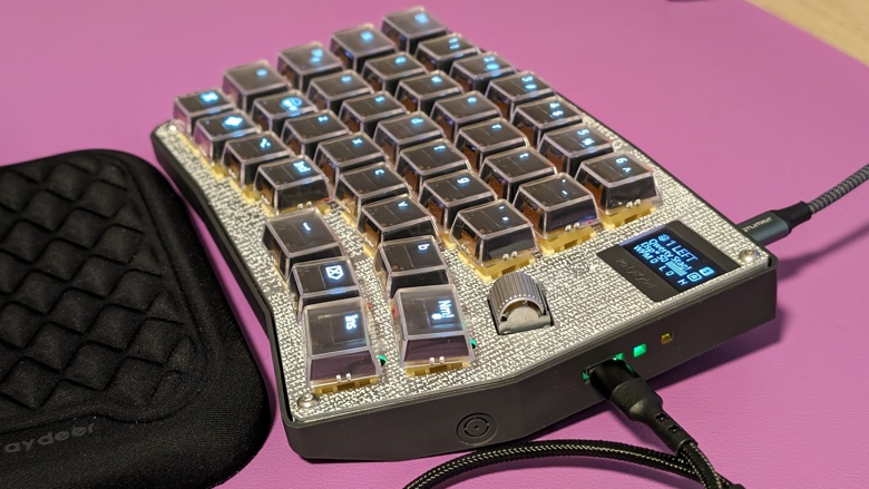
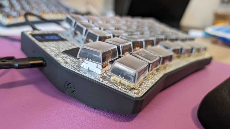
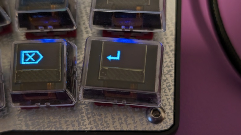
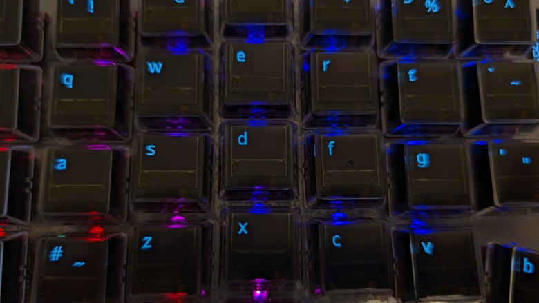
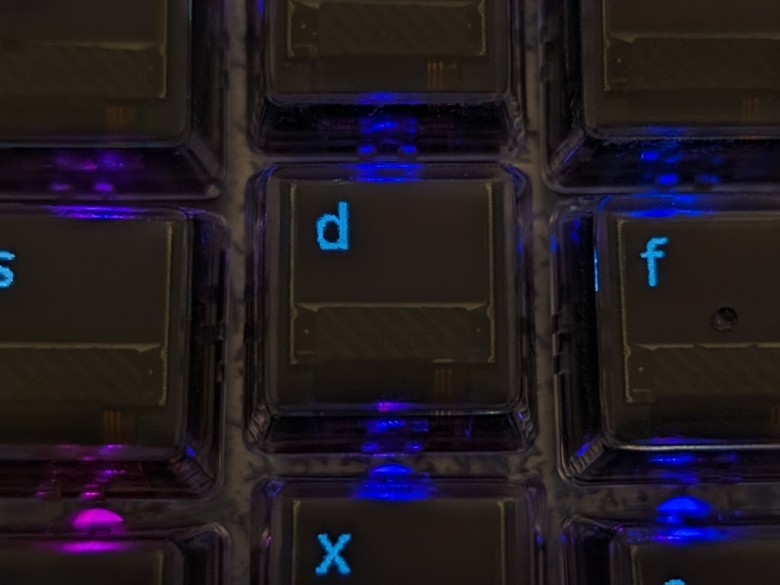
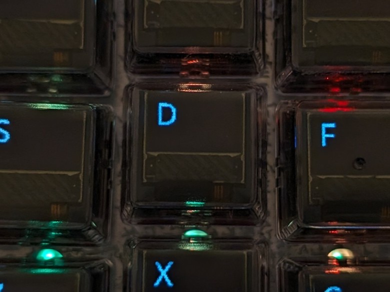
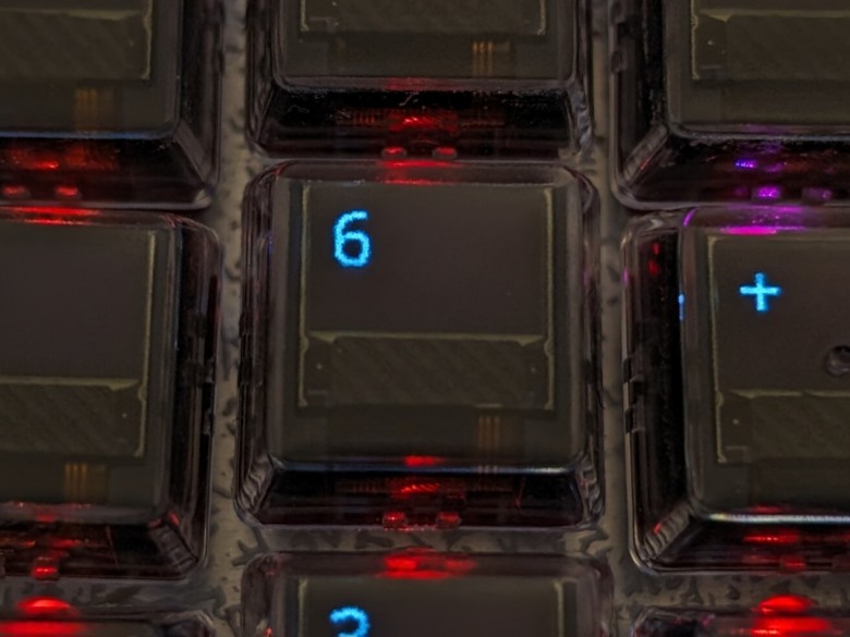
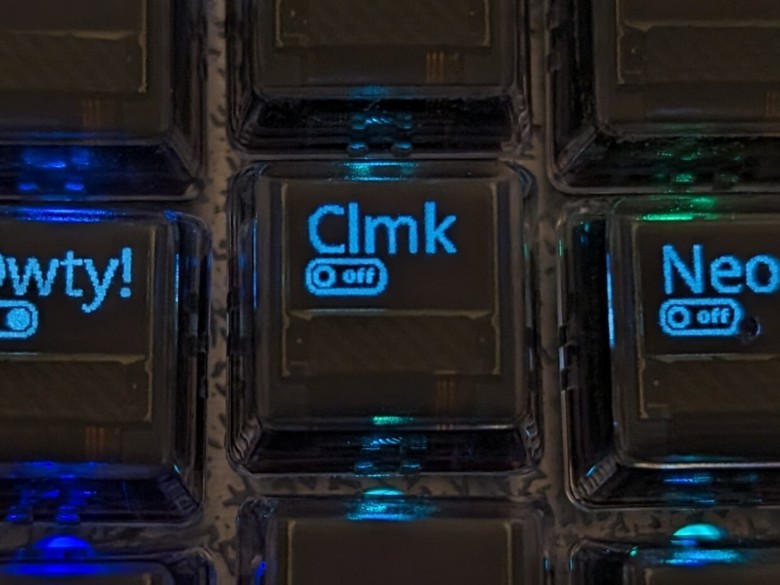
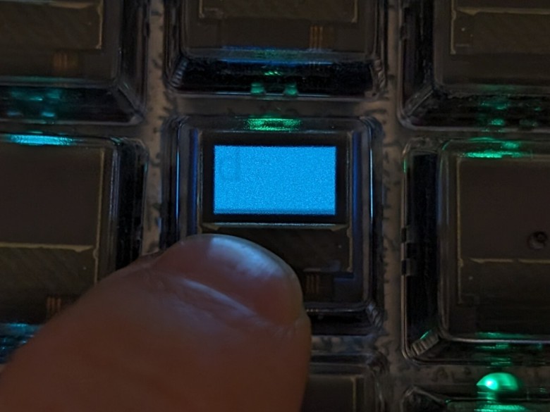
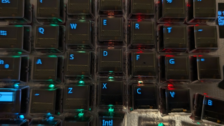
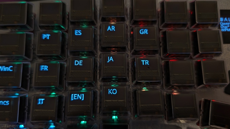
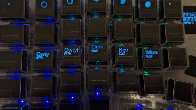
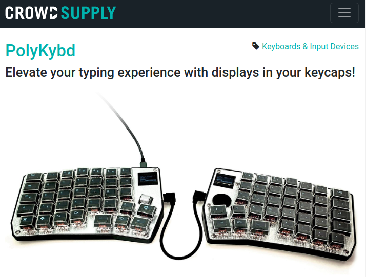
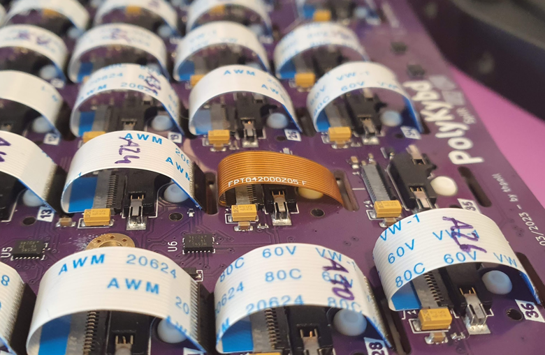
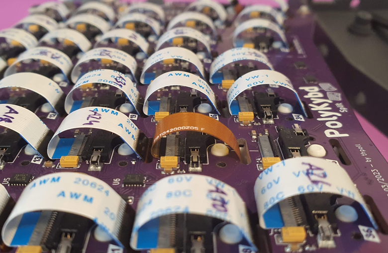
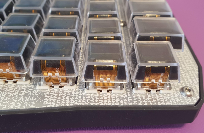
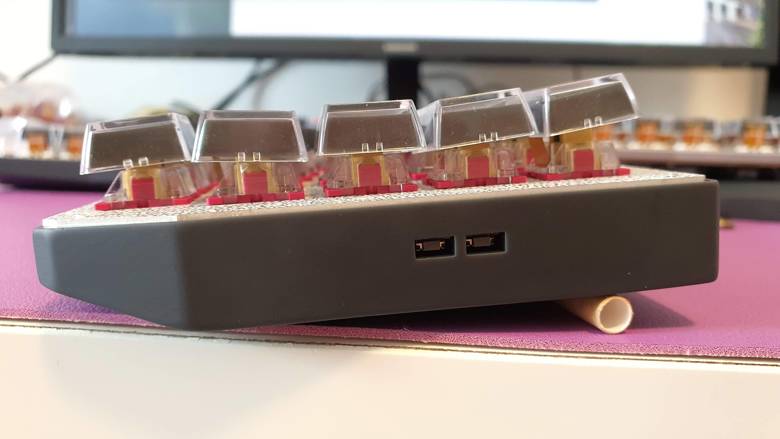
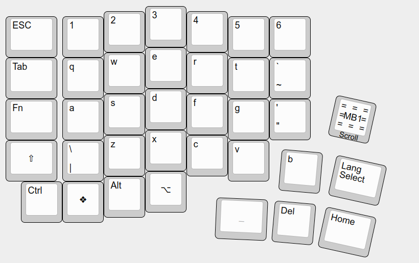
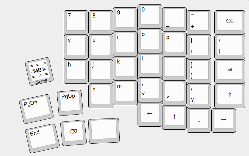
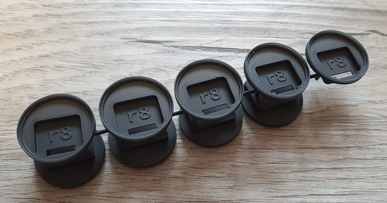
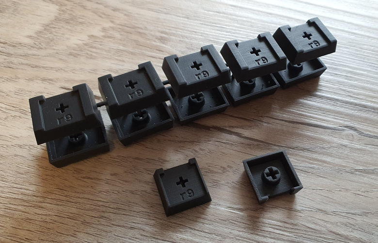
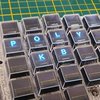
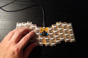
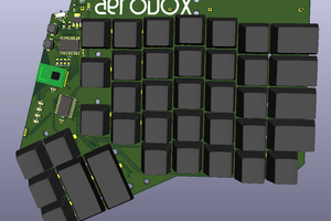
Mechanical split keyboard with OLED displays in the key caps
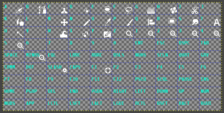
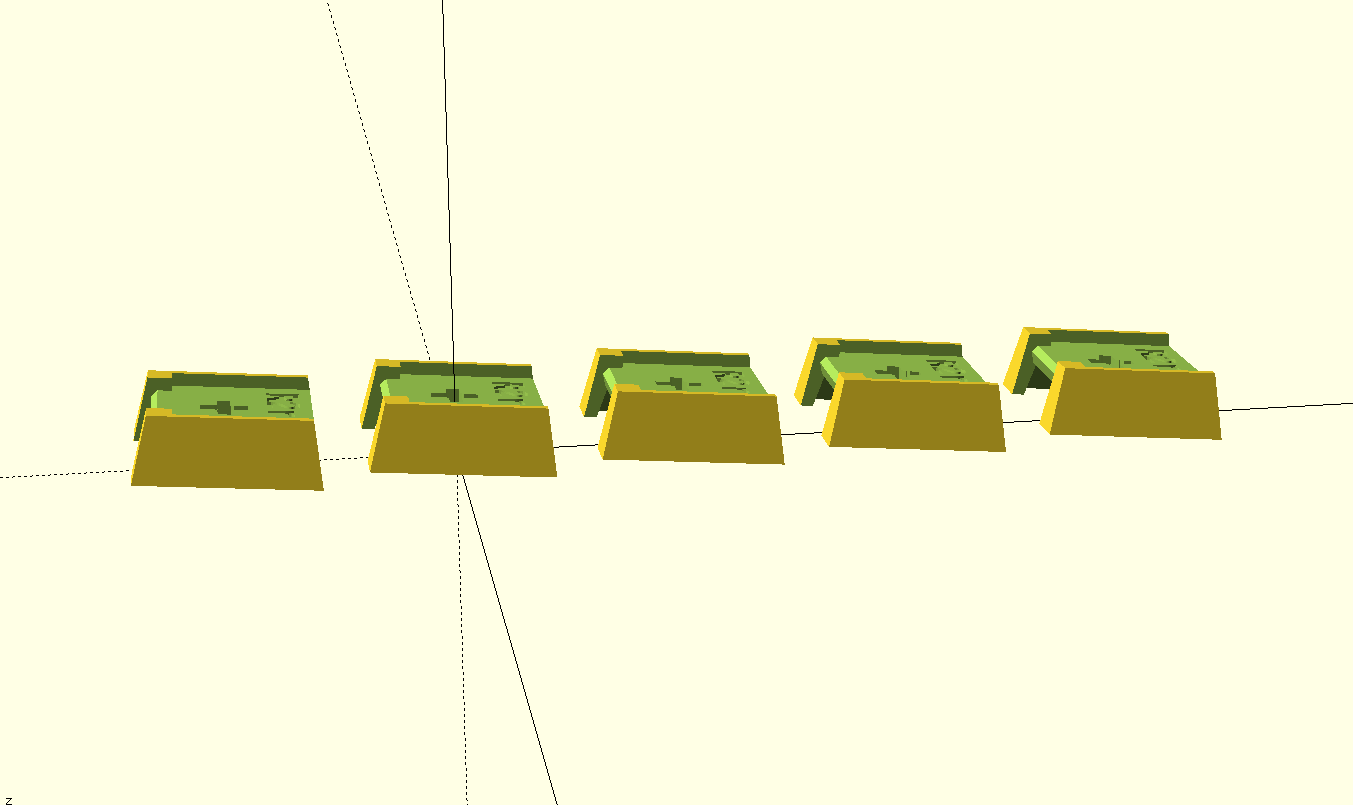
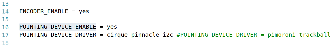
It uses QMK as firmware for the keyboard and controls the displays via SPI and chained shift registers to address all displays separately or even all at once.
Other keyboard sizes might follow later (maybe a 75% version and a macro pad?).
There was a Hackaday post earlier about this project: https://hackaday.com/2022/10/17/poly-keyboard-has-screens-in-every-key/
Current Status
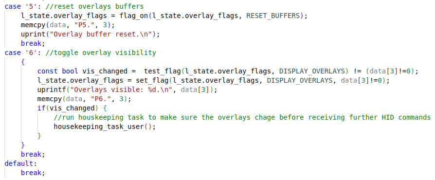
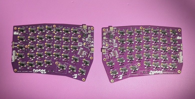
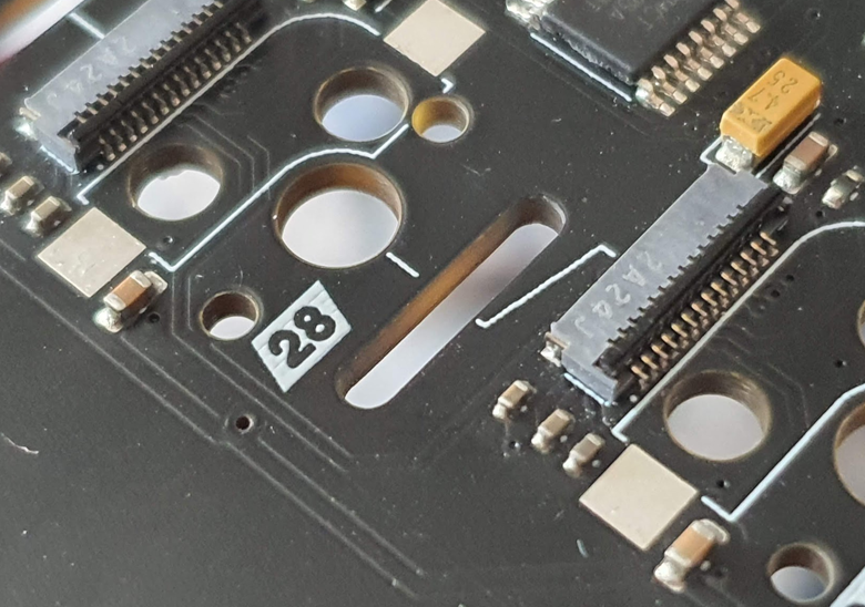
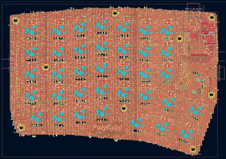
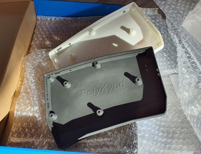
The HW development is almost finished. The firmware still needs further improvements as it is currently really just a work in progress to show what is possible.
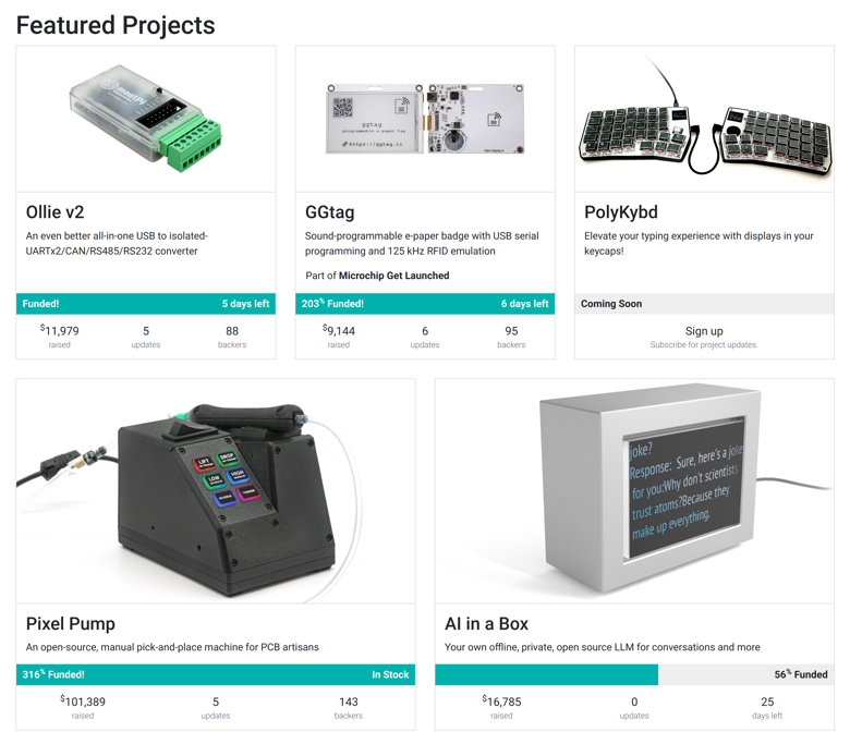
However, the build guide is ready at https://github.com/thpoll83/PolyKybd#readme and I am happy to share that there is a pre-launch page on CrowdSupply in case you are interested in getting a kit: https://www.crowdsupply.com/polykybd/polykybd
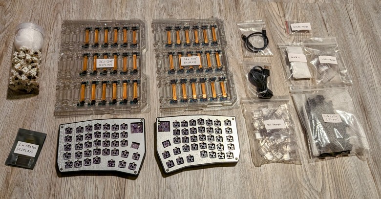
Overview
More details will follow, please feel free to dig around in the git repos and ask questions.


 deʃhipu
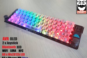
 Pamungkas Sumasta
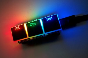
 Simon Merrett
Hello! I'm wondering if you have any plans of making some boards available to beta testers? I use macros to help with my work quite often, and this is something I've been looking for for a while. I'd love to help out with the project!