 thpoll
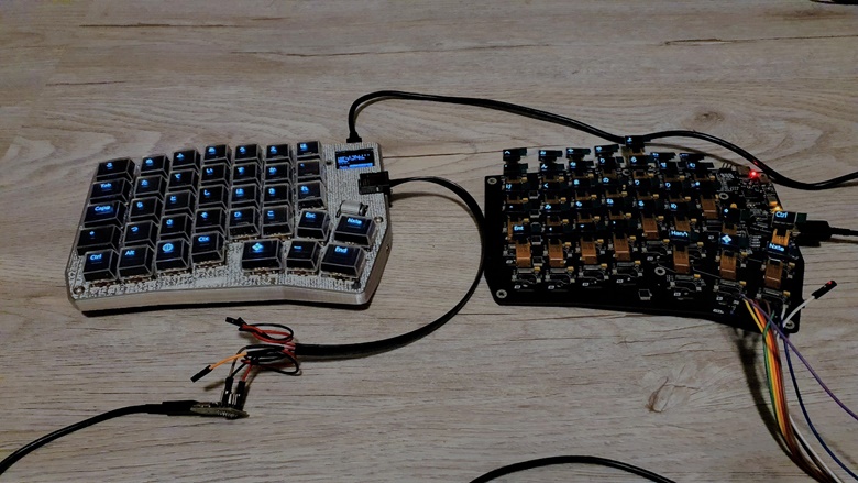
I had a good time designing the right side and it is really satisfying to see it turning on without any issues:
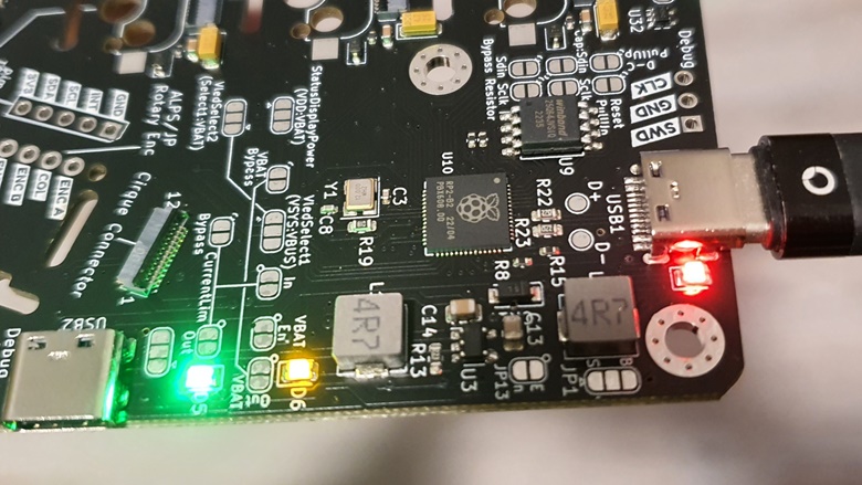
As you know from earlier posts, I used the right side to test a new hardware iteration that includes an on-board RP2040, USB-C, more flash memory, etc. So there was some risk that the board might not even boot up.
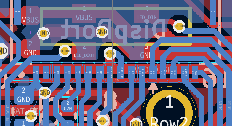
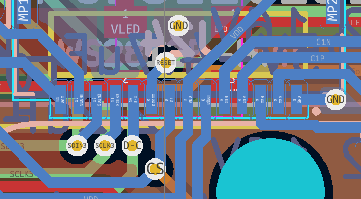
To give myself enough possibilities to tweak and debug things, I added a lot of solder jumpers and also pin headers to connect to the most important data via a logic analyzer: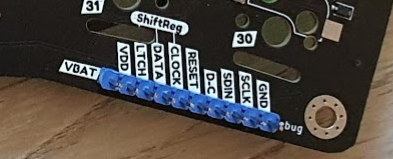
Before I had to solder some wire to test points here and there just to check my SPI signals.
But the new board has a problem (makes me cry a bit), which makes it only usable as dev board and not as (Poly) keyboard. Disappointing, as all my PCBs on this project so far proved to be fully functional prototypes.
Here comes my list of what works and what doesn't.
Success:
- RP2040 with 8MB Flash and USB-C works (obviously)
- The non-inverting buffers do solve my issue with the data glitches I experienced, it was indeed a fan-out problem (😆 so happy that this is off the table)! Huge thanks to my co-worker Peter who suggested that change. This was my last electrical issue :)
As this problem was solved, it was time to increase my SPI frequency from 400kHz to 16MHz. That success made me go further so that I increased also the frequency for the shift registers to 16MHz and it works! It was a pure software change, but with the data glitches before, I didn't dare to tweak the way the shift registers operate.
Finally, updating the displays is amazingly fast, no way to recognize any delay 🤯.
Now everything runs on 16MHz and I can see my 10$ logic analyzer reaching its limit. For hardware debugging I have to reduce the clock, otherwise it misses some signals (Well, I should maybe invested into a proper one... any affordable recommendations? Maybe a Kingst LA2016?).
- Successfully tested the new 0.42" displays with the SSD1315 chip! These were fully compatible with the old ones having the well known SSD1306 - no change needed.
- I also consider the solder jumpers as a big success. These let me re-wire pieces of the circuit without any new iteration (like the power supply of the displays, unfortunately these really need a voltage of about 3.6V, 3.3V is not working). In the future, I will remove them as they needed quite some space on the surface though.
- Right and left side can currently communicate via my RJ45-to-UsbC franken-connector and you cannot damage the boards by confusing the two USB-C plugs:
If you plug the side connector into any other USB-C device it will look like an analog headphone, which is harmless.
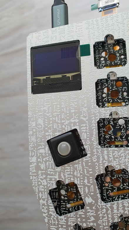
- A bit over-enthusiastic, I also decided to use an OLED status display which does not come on a break-out board to avoid any supply-chain issues with 3rd party PCBs. It's a bare OLED display with a 30 pin FPC (I2C) which I got from my trusted display supplier:
It did not turn on right away as I tied all reset lines together and the displays from the keycaps were initialized after the status OLED and so the reset triggered too late. To fix that, I now initialize them together and and we are good!
No Conclusion Yet:
- The pimoroni trackball (see picture above - fits just perfect), which can be used as alternative to the rotary encoder and is already soldered on for the current board, but I just did not configure it in QMK yet.
- There was also no time to check the cirque connector, but this will be still possible of course. It could make a nice addition or alternative to the trackball as mouse input.
Failure:
So here is the problem... Can you spot it? (new one above, old one below)
Well, it's easy if you see it right next to each other...! I changed to another FPC connector with 14 pins because the customized displays will have less pins to get rid of redundant ones (and therefore will be 1mm smaller and fit with more switches). There was even a KiCad footprint for the new socket, so I was very happy. And here is the problem... I did not compare it with the old footprint and there, pin 1 is on the right. The new one has it on the left!
Everything is electrically working, but the displays will face downward when putting them into the key cap 😭😭😭. And that means I have to make one more PCB to fix that!
What's Next?
Well, testing the trackball and getting a cirque to work and of course layout a new PCB, this time with pin 1 on the correct side!
So there will be just another iteration of the right side, hopefully already in a "final" state.
Discussions
Become a Hackaday.io Member
Create an account to leave a comment. Already have an account? Log In.