 M. Bindhammer
Introduction
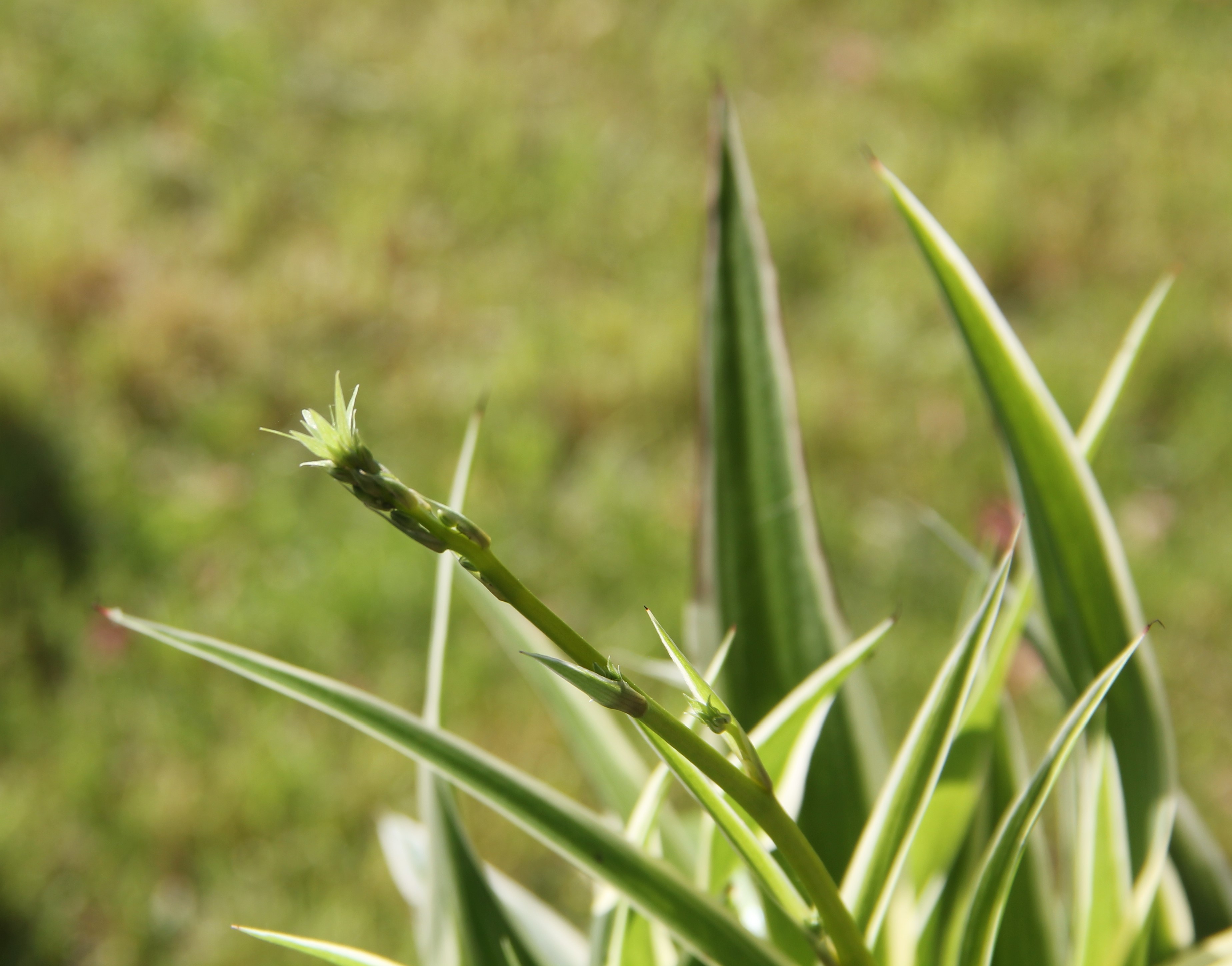
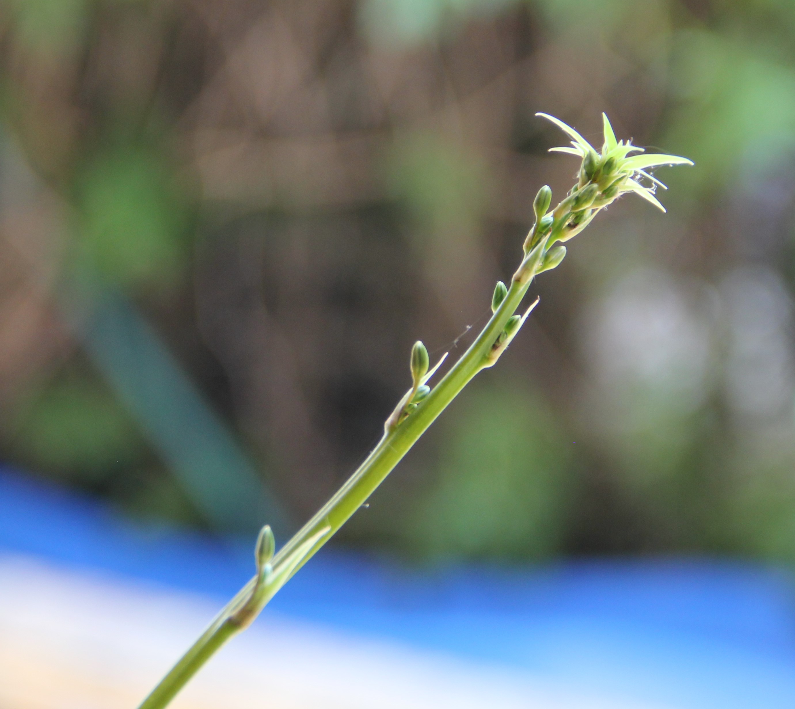
Chlorophytum comosum, better known as green lily or grass lily, filters up to 95 percent of pollutants such as formaldehyde, benzene, or carbon monoxide from the air, according to a NASA study. So why not use plants to improve the air before you breathe it? Since about 500 g of water is released with respiration over the course of a day, this could be used to water the plants.
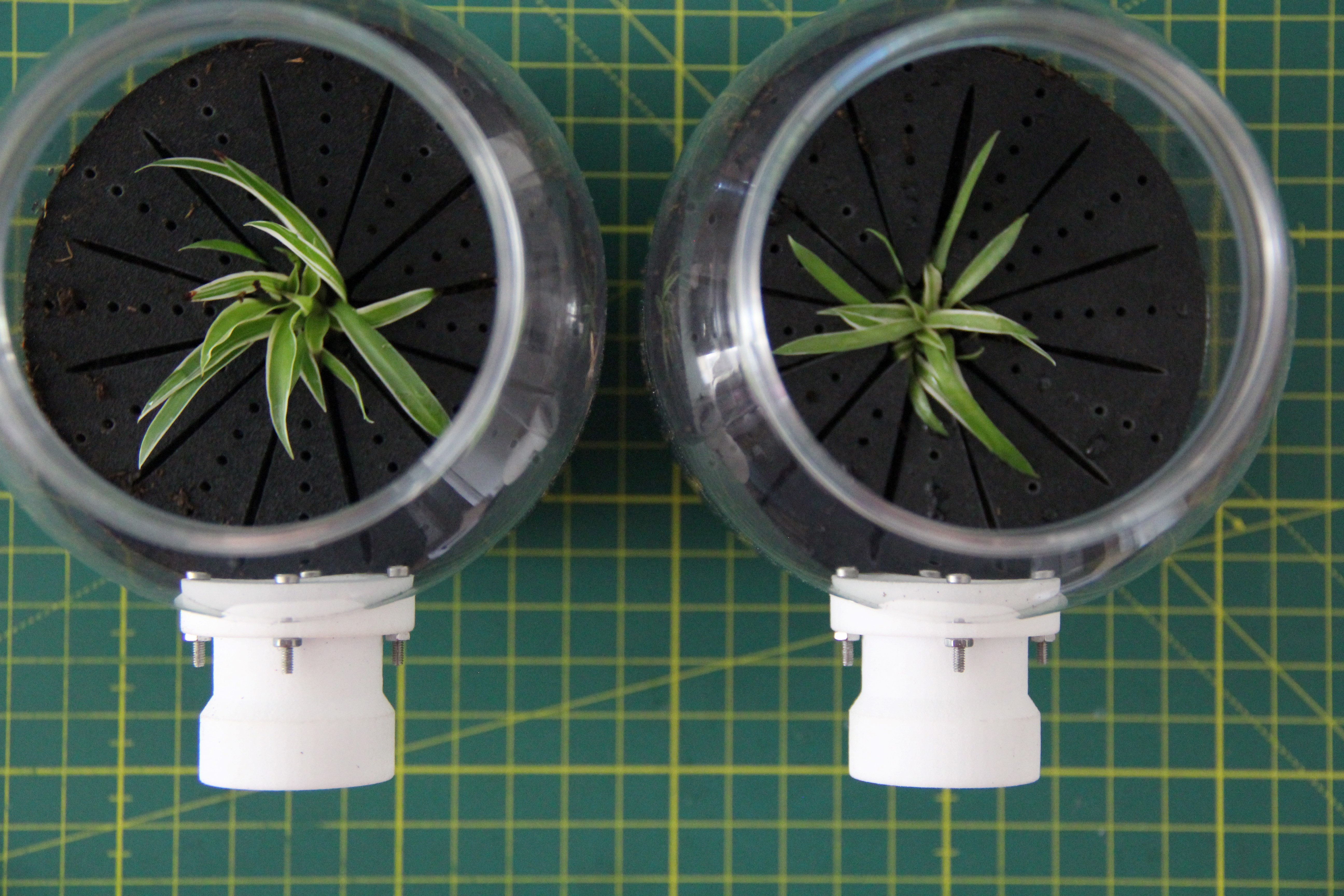
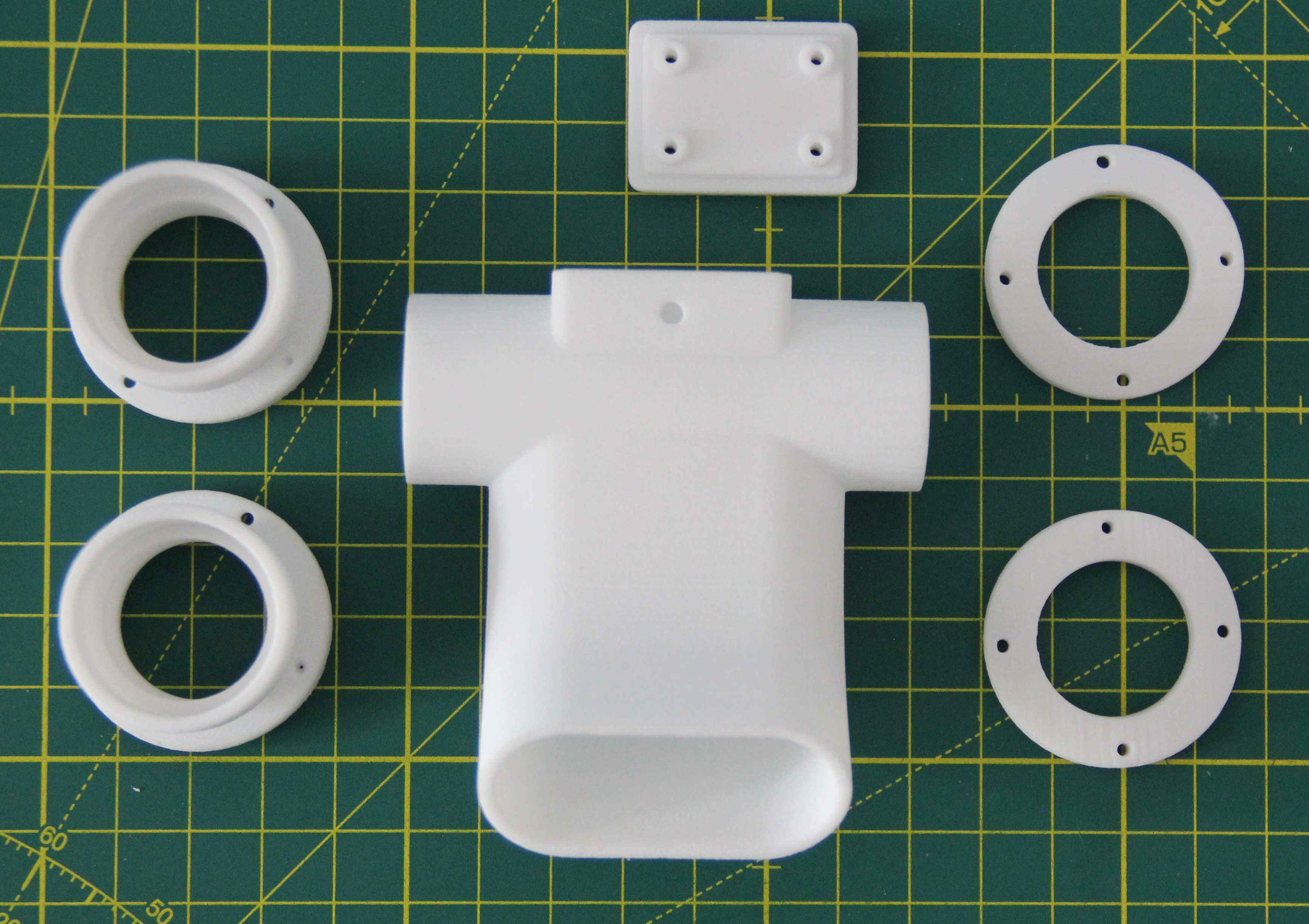
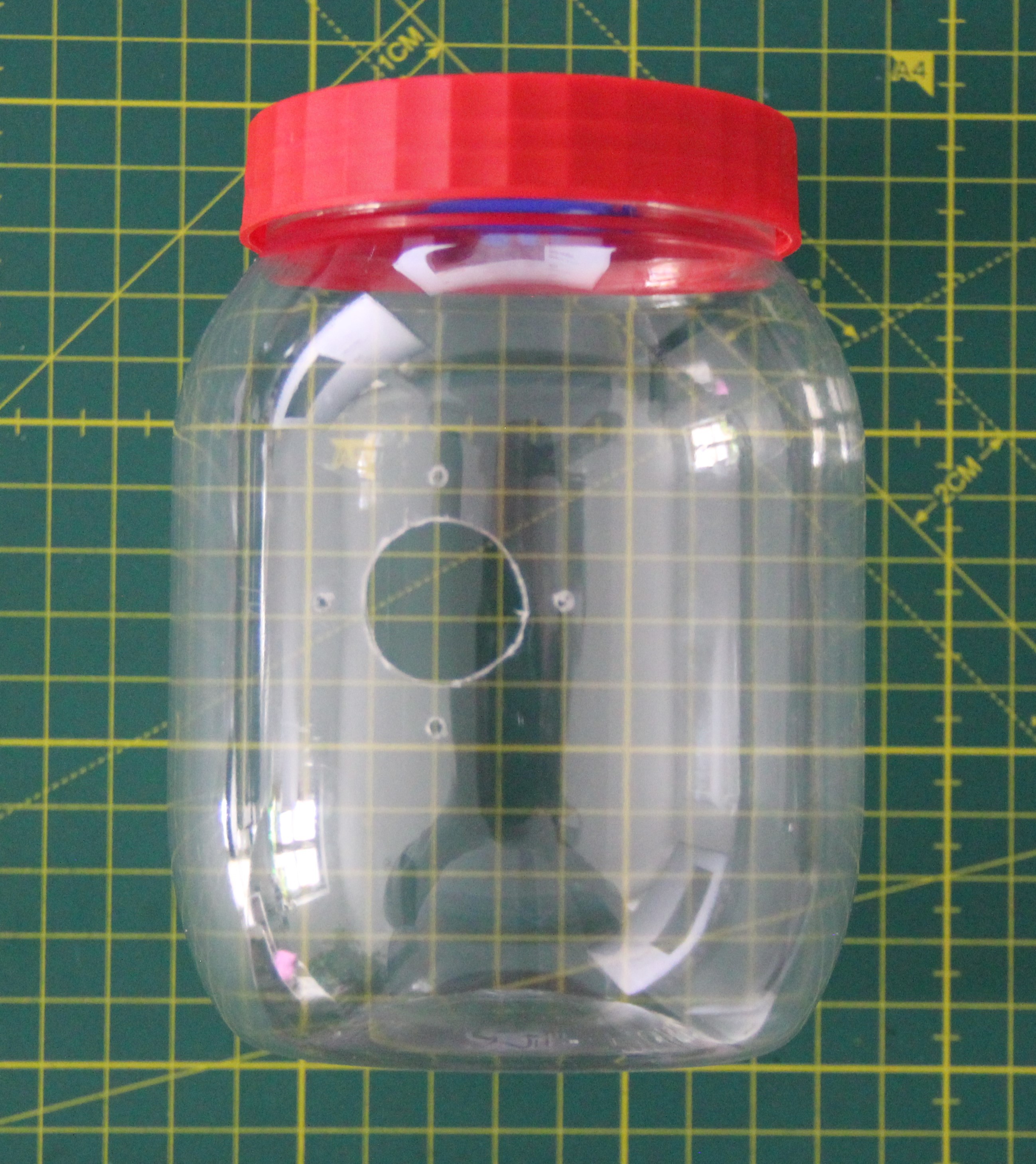
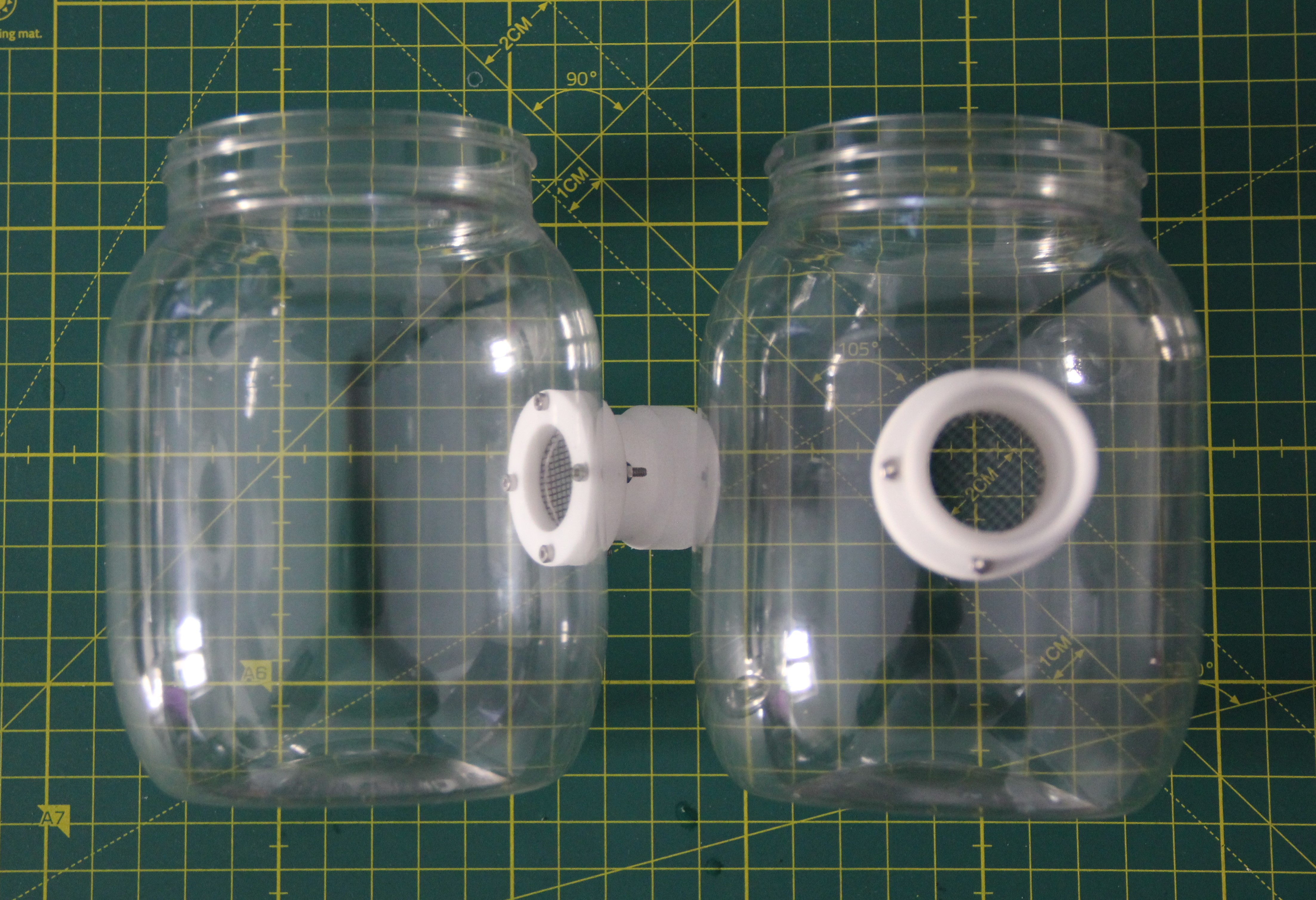
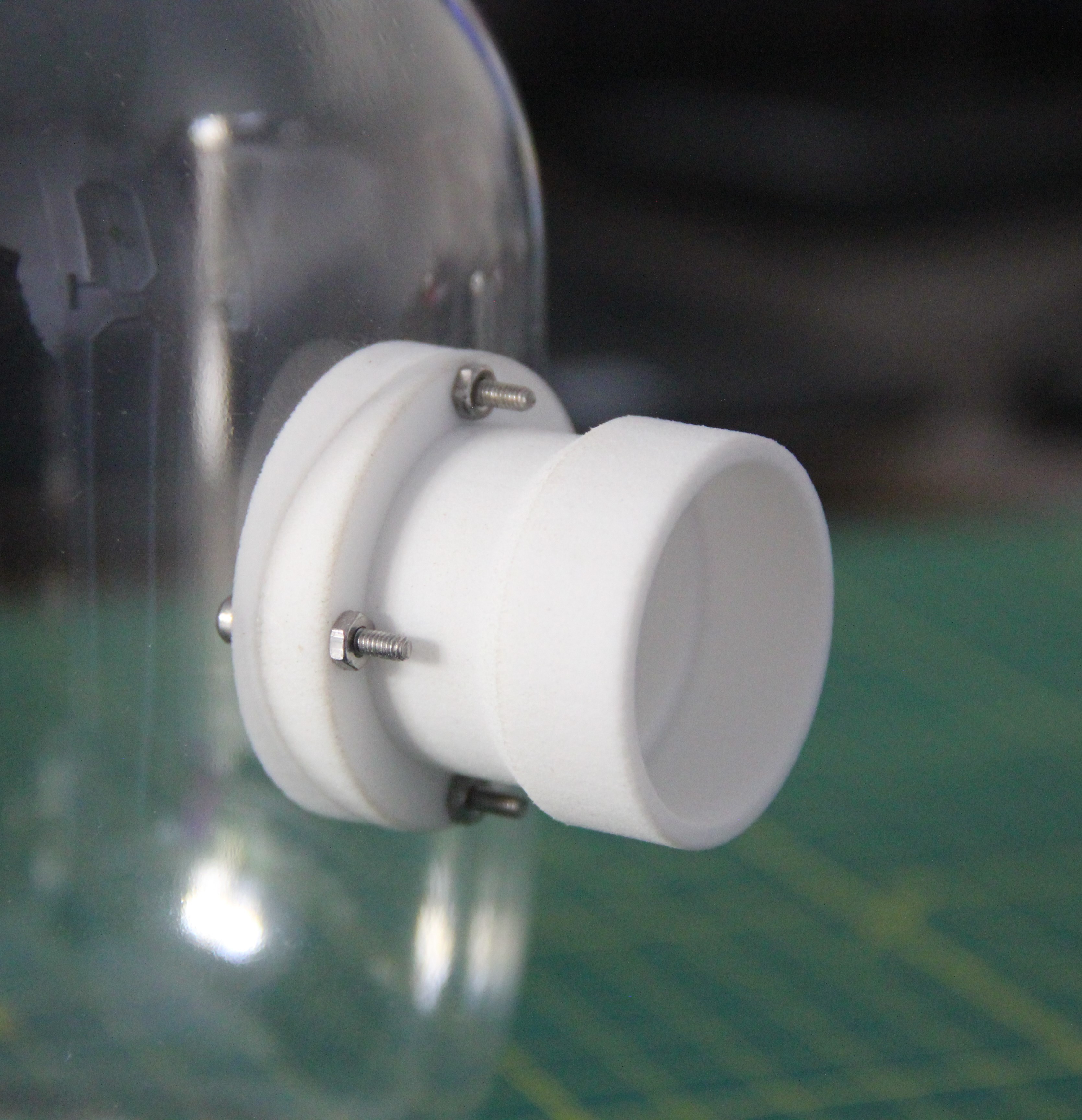
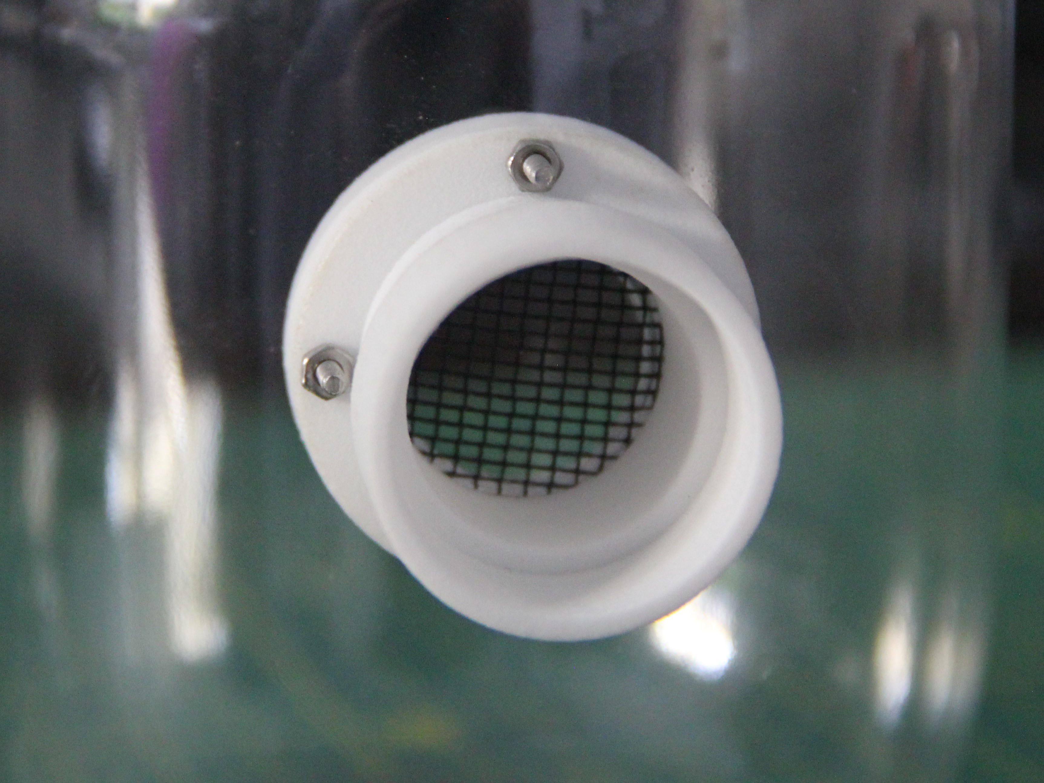
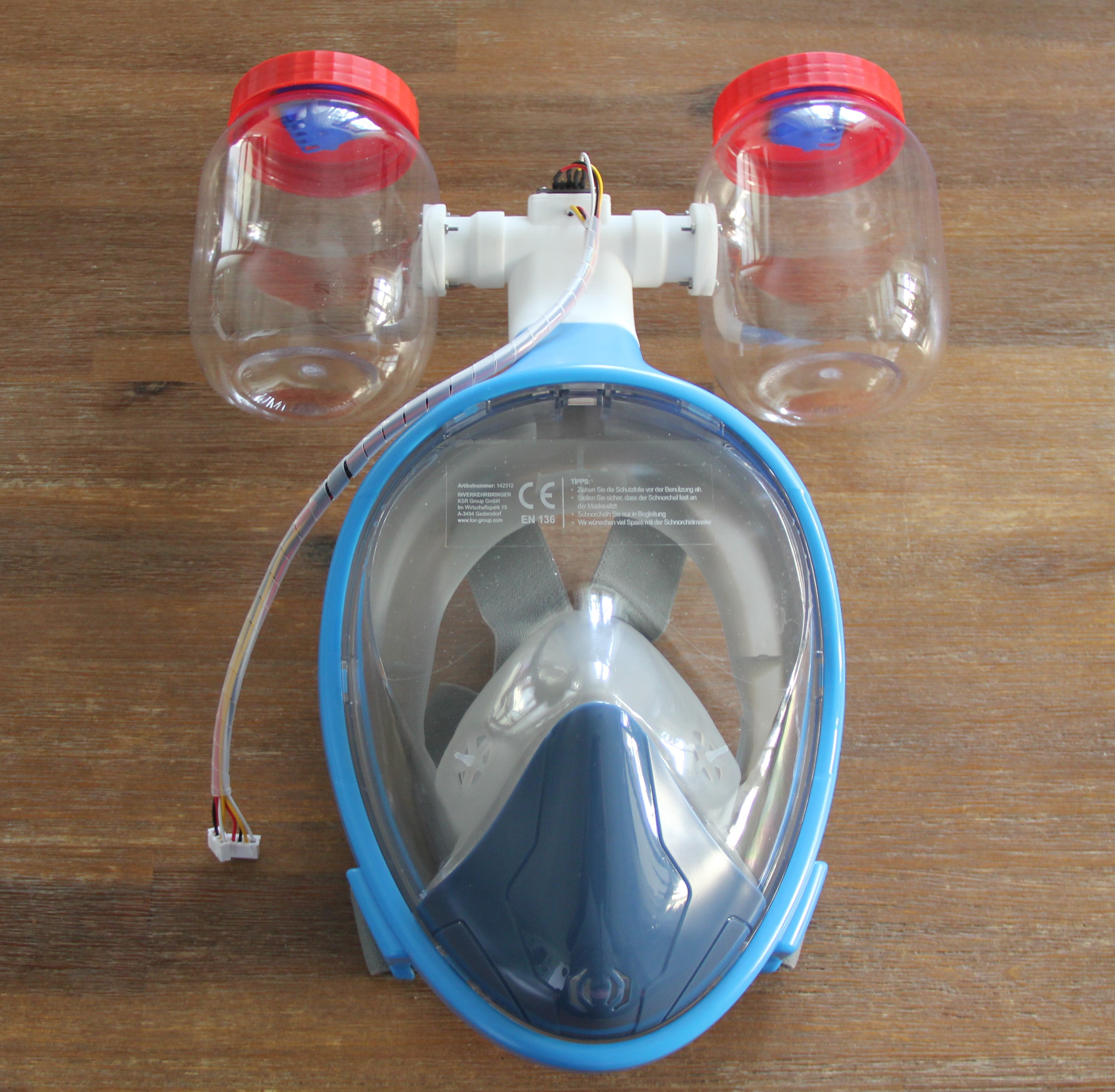
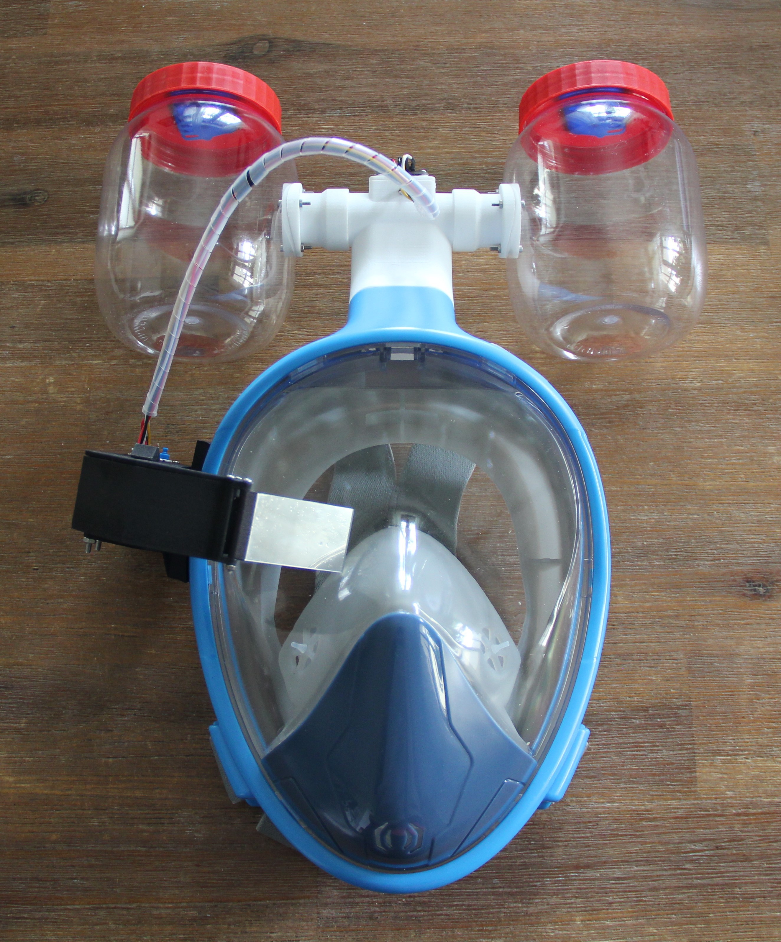
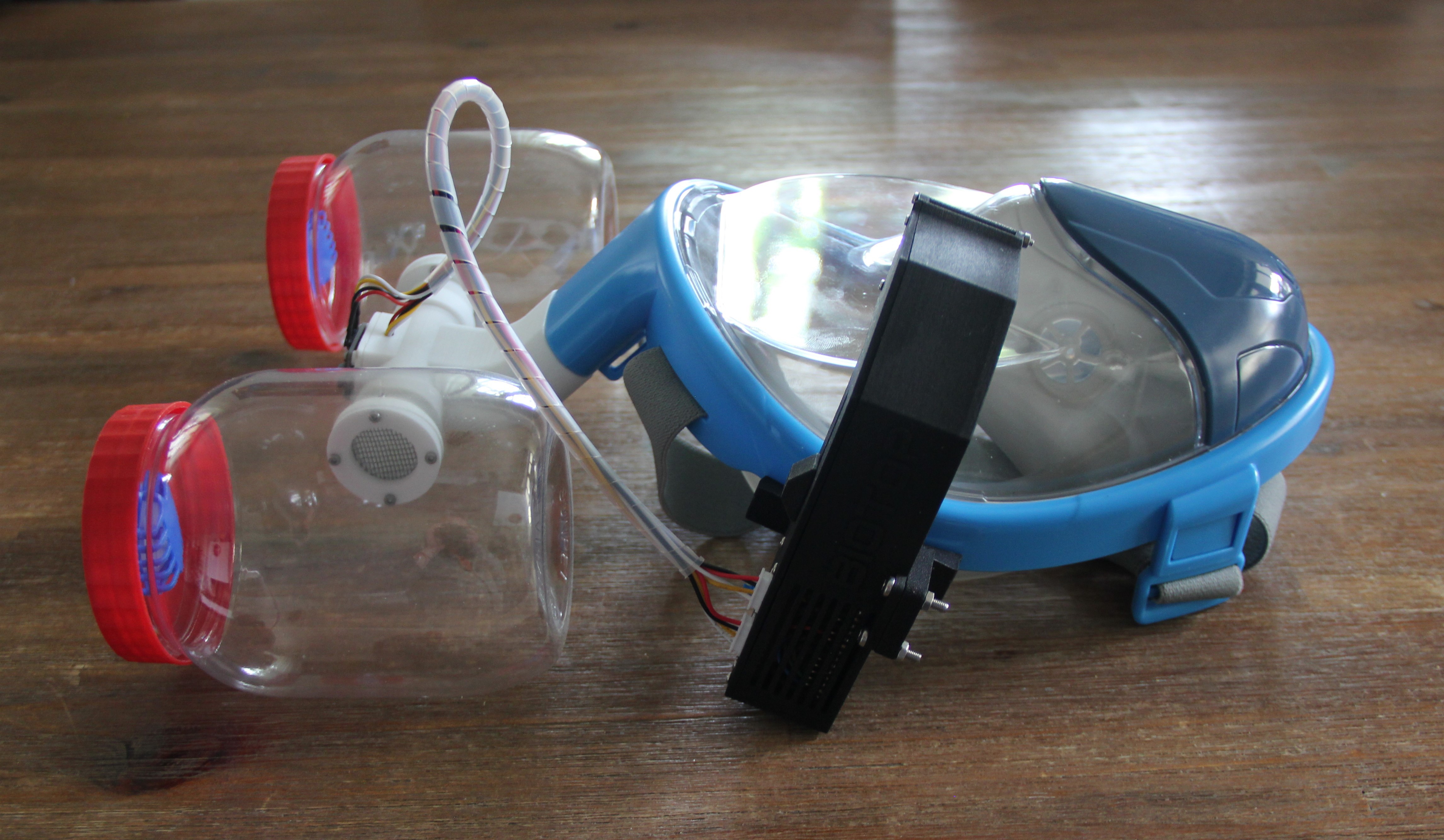
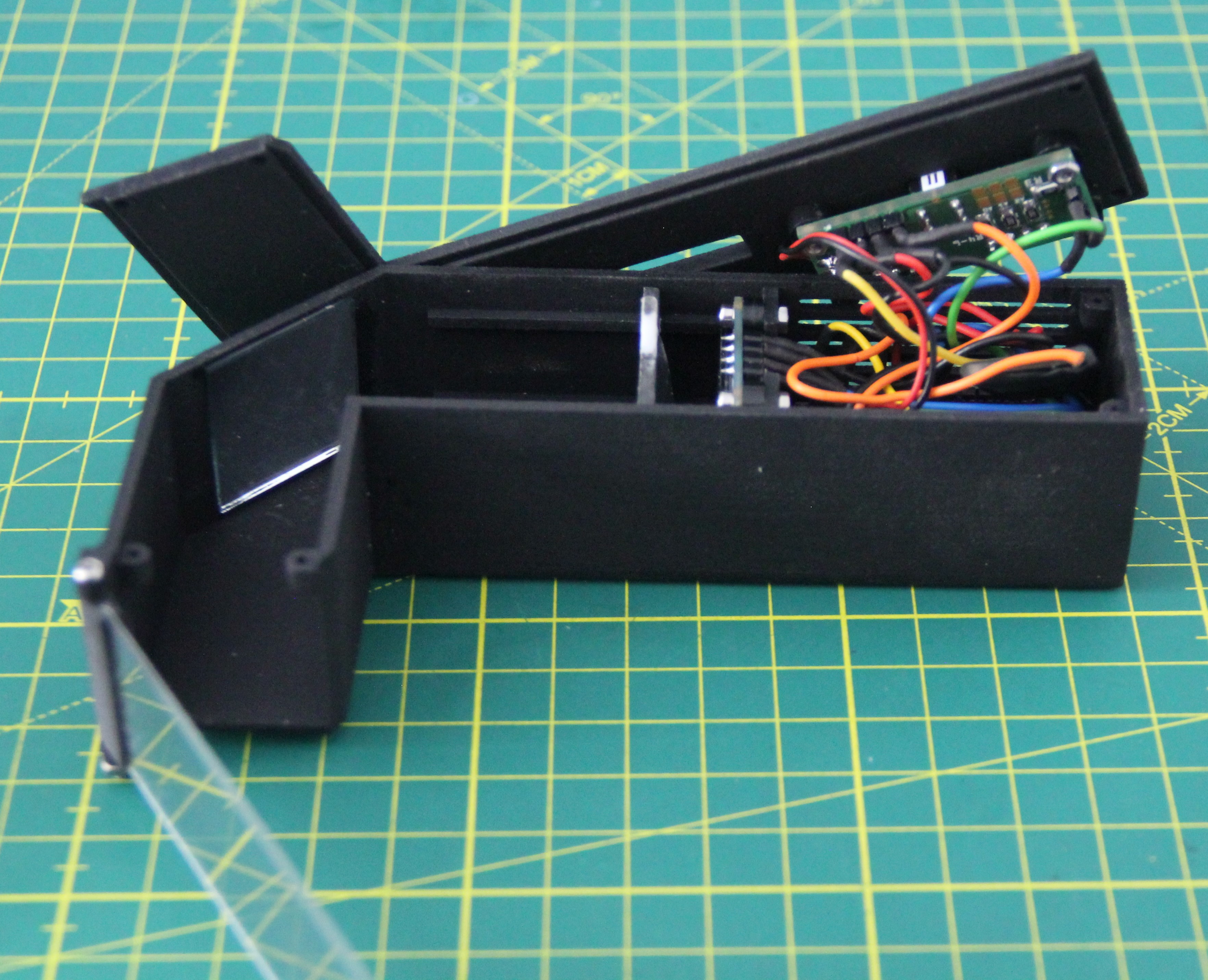
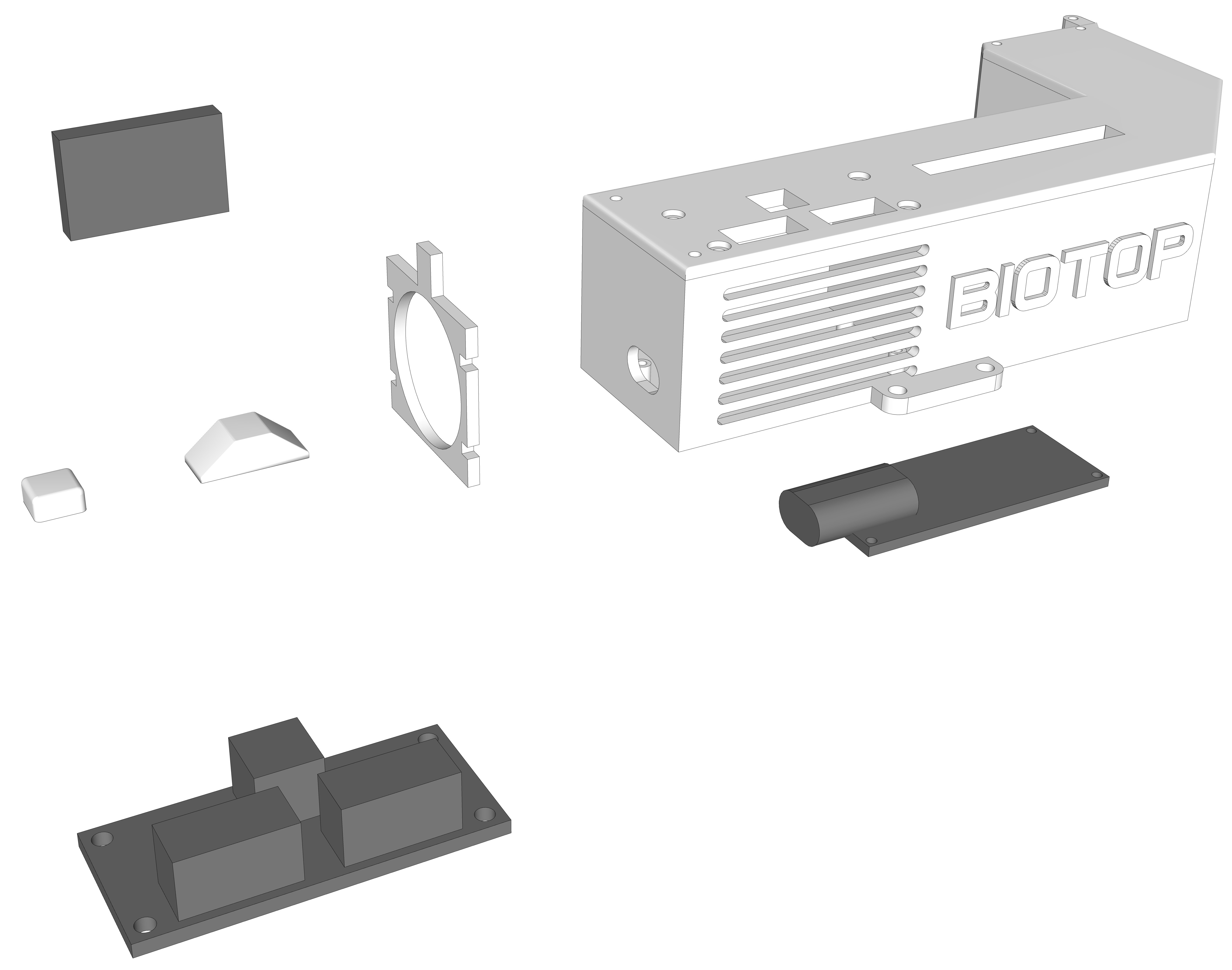
The mask utilizes a 180-degree view diving mask and two 750ml plastic food storage containers as mini biotopes. Important in the design was that the diving mask is not damaged in any way, for example by mounting holes. The two biotopes are connected to the mask using a 3D-printed adapter. The two biotope containers can be removed so that you can grow different plants. The mask also features 3-D printed AR glasses and two gas sensors, one on the inside and one on the outside. The values are displayed on the AR glasses. This allows you to experiment with different plant species. Other data can also be transferred to the AR glasses via Bluetooth. The AR glasses can be removed to use for other projects. Other sensors can be connected as well since the glasses have basically two I2C ports with a 3.3V power supply each.
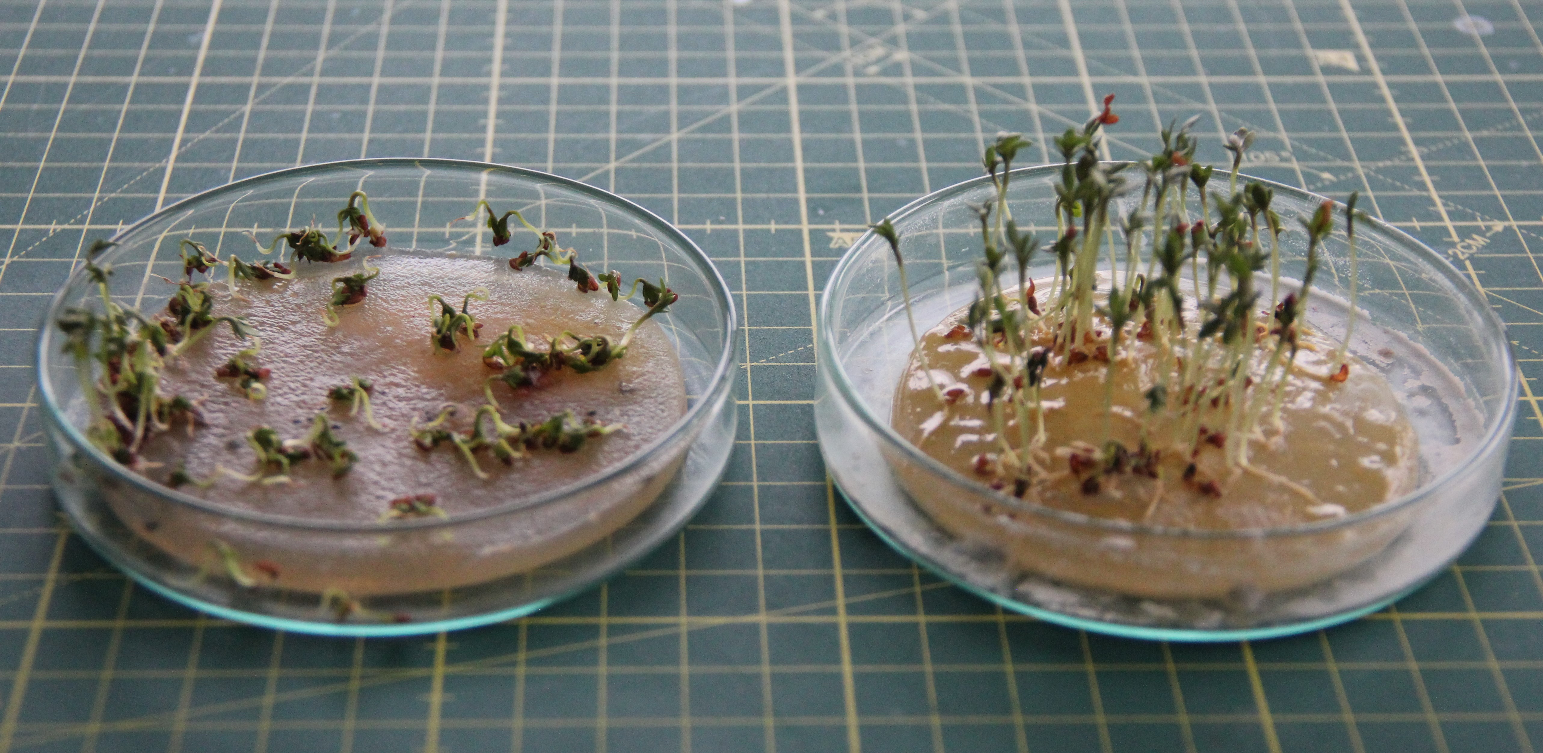
This project sees itself as a mixture of art and science. It is intended to draw attention to devastating environmental pollution. According to the World Health Organization, air pollution is now the world's greatest environmental health risk. However, the real goal of the project is to achieve a symbiosis of two biological systems through technology. While working on the project, I have already gained scientific knowledge, for example, that sodium alginate is suitable as a substitute for soil.
The mask can be used for a student science project or at exhibitions, fairs, and vernissages. Another application would be aromatherapy.
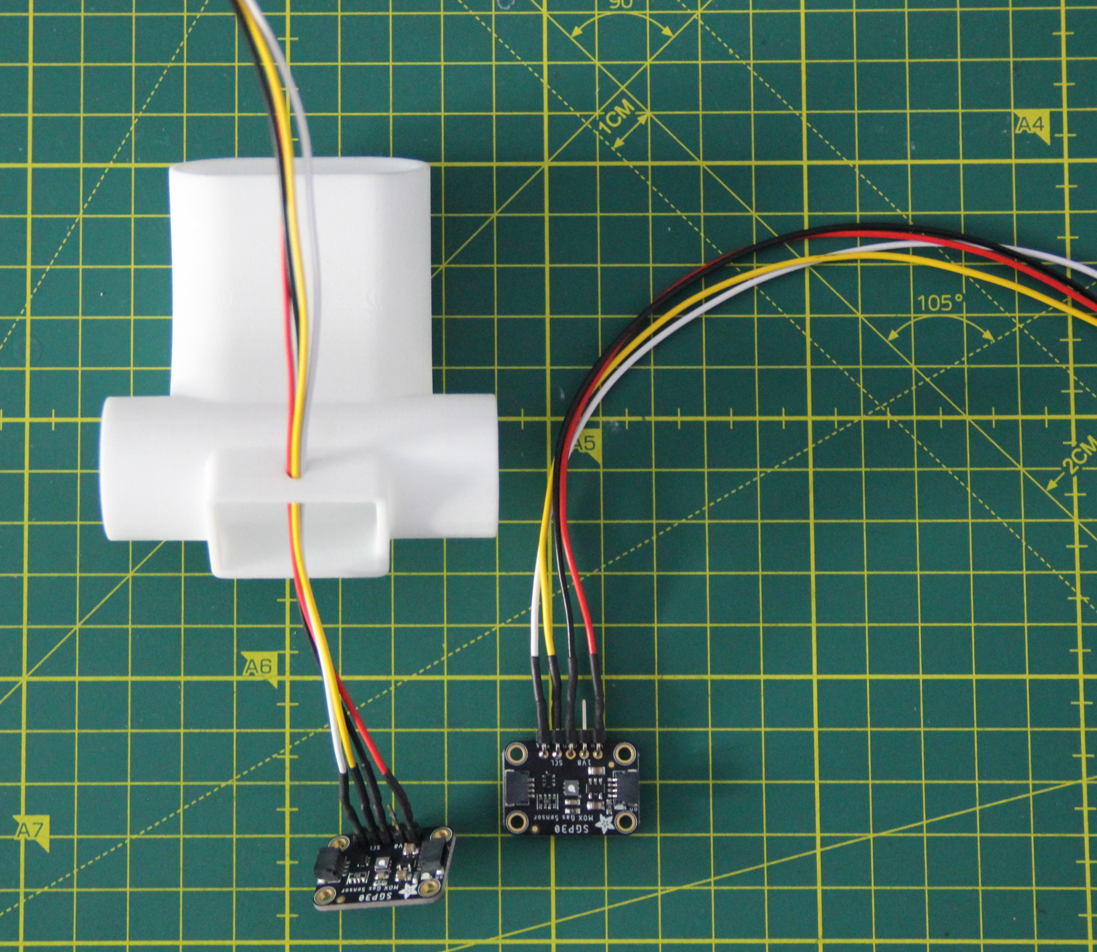
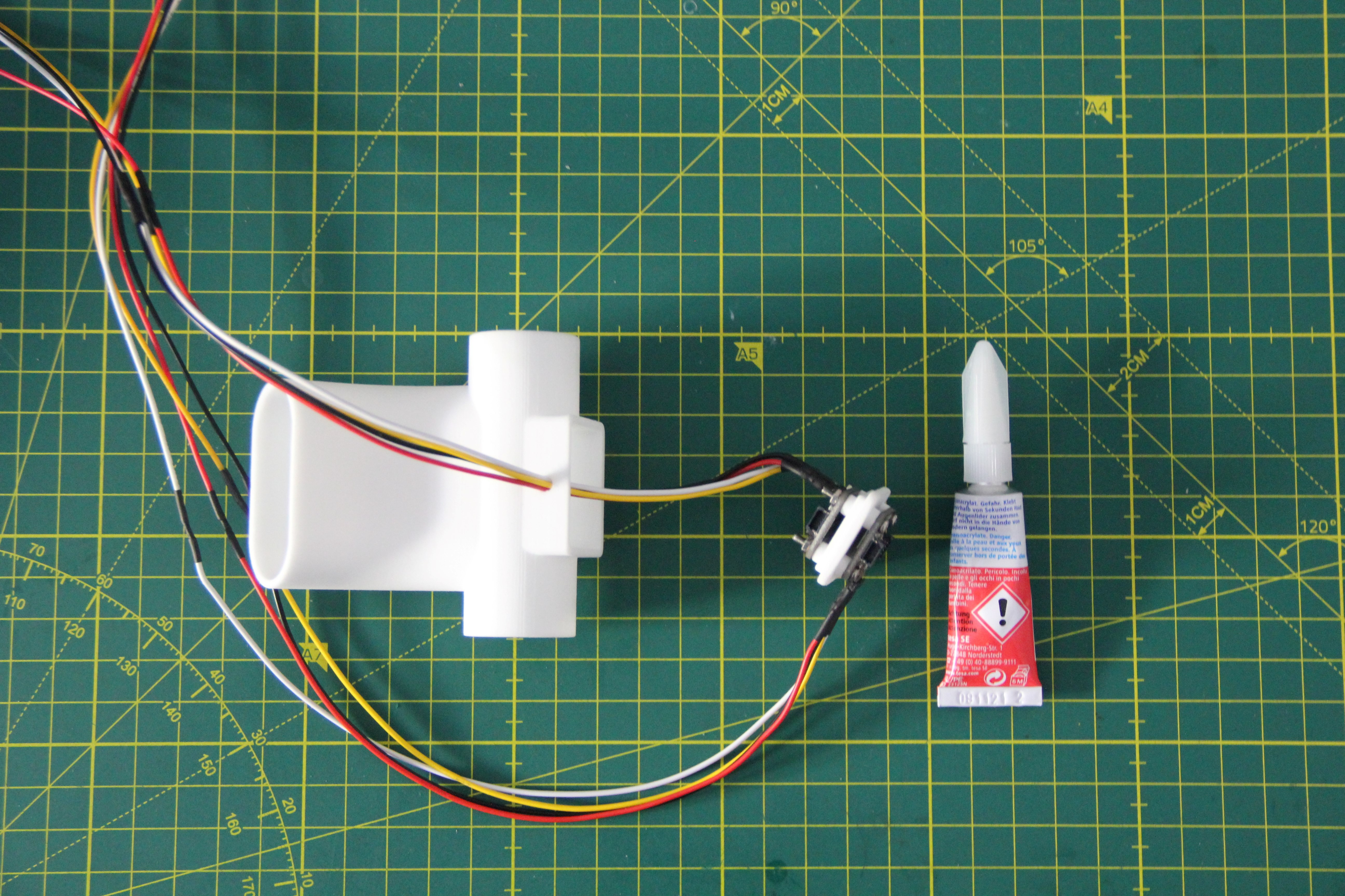
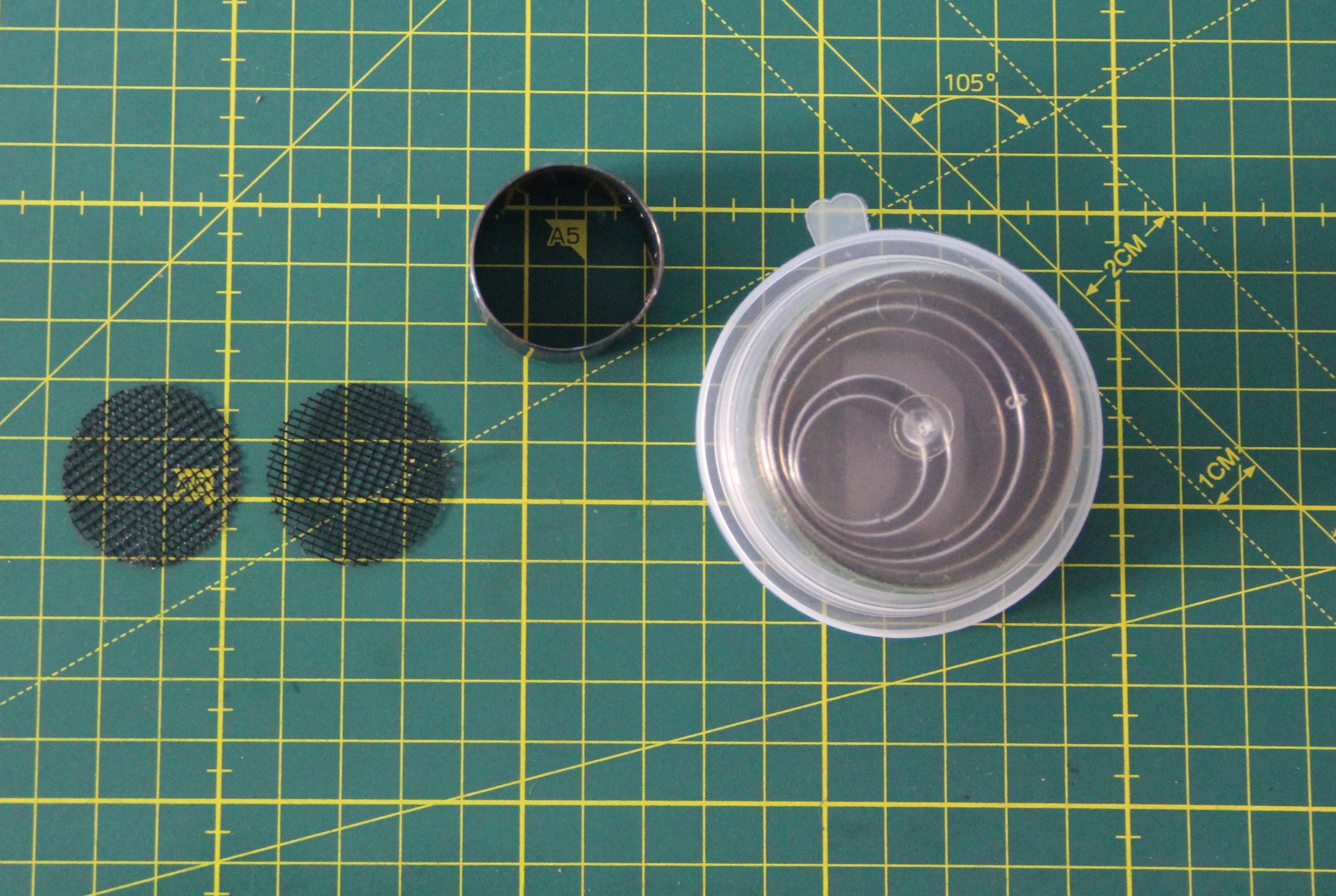
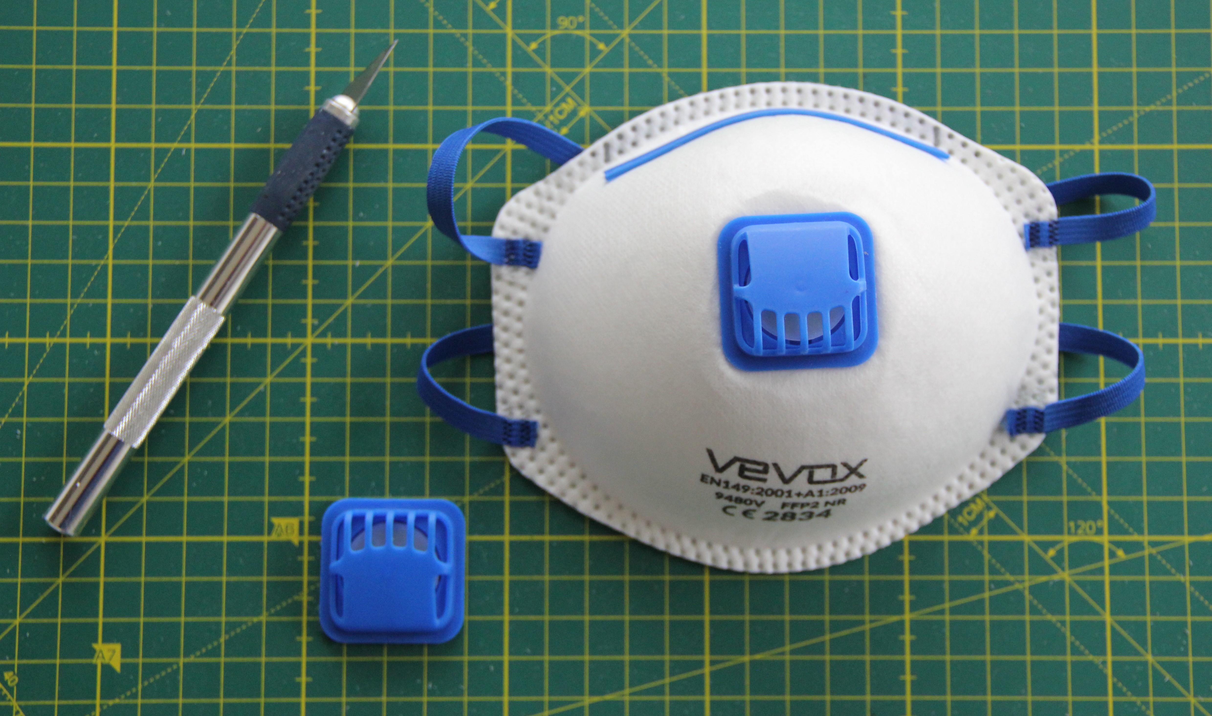
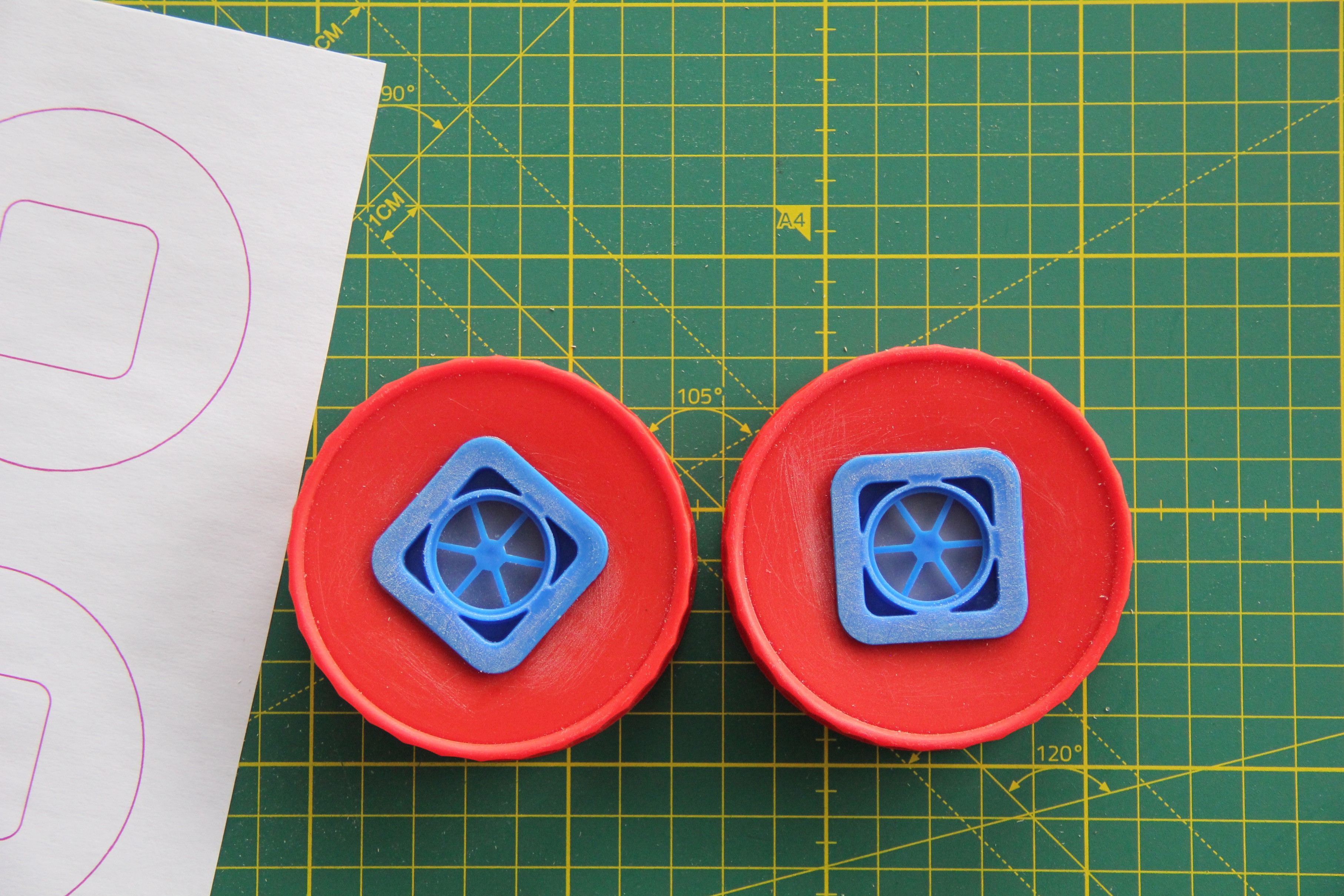
Breathing in and out with the mask proceeds as follows. One-way air valves are embedded in the two lids of the plastic food storage containers which open on inhalation and close on exhalation.
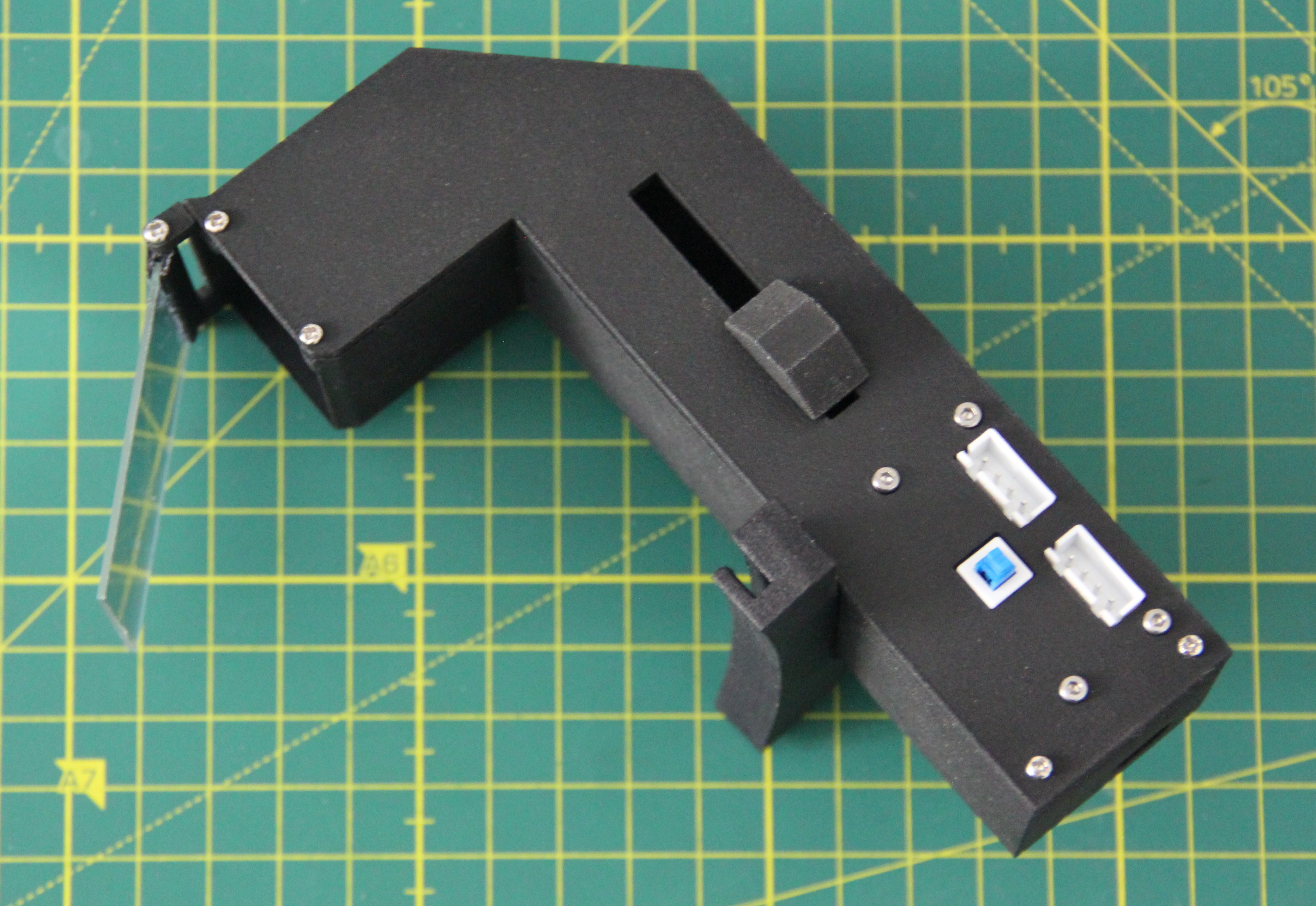
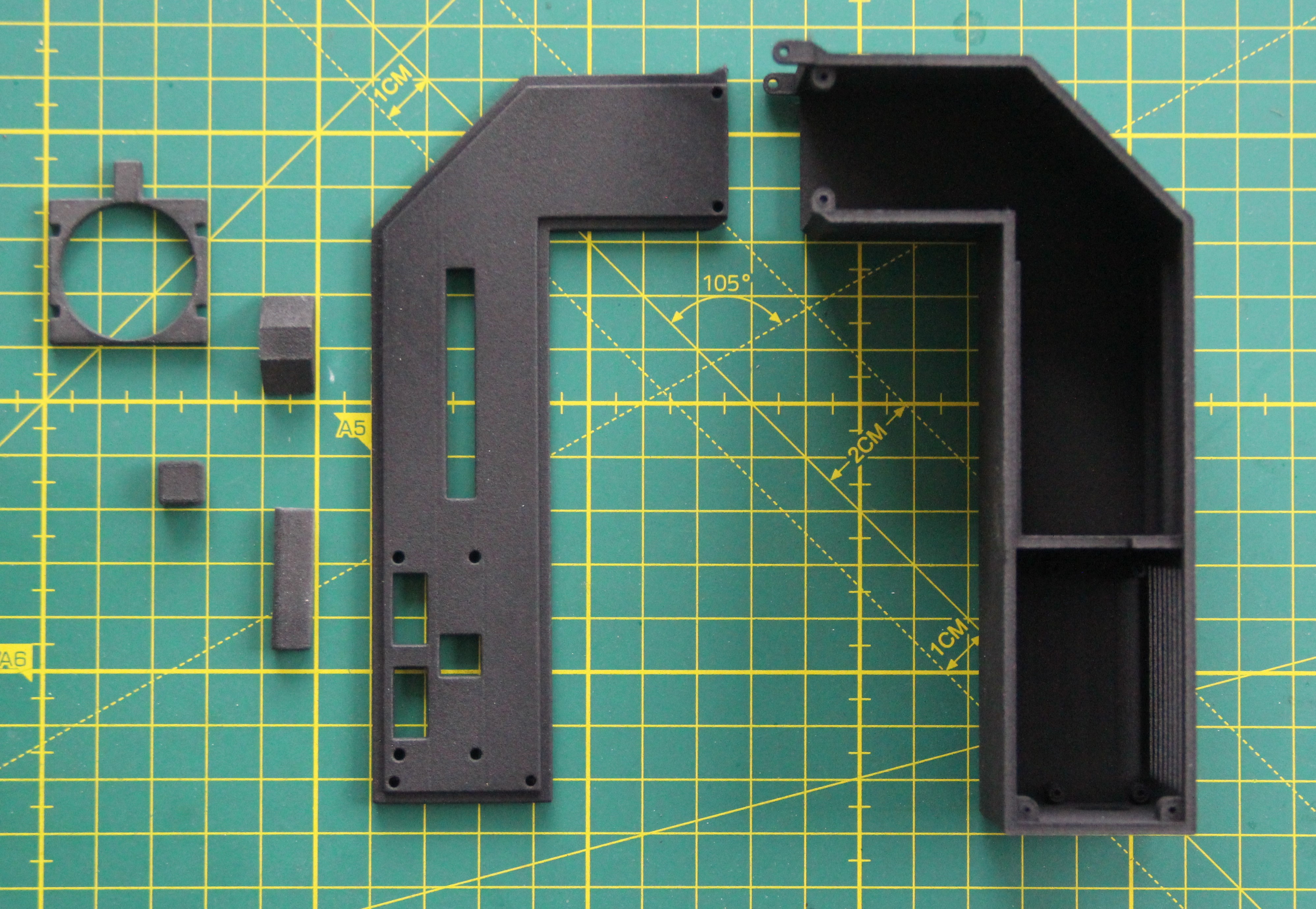
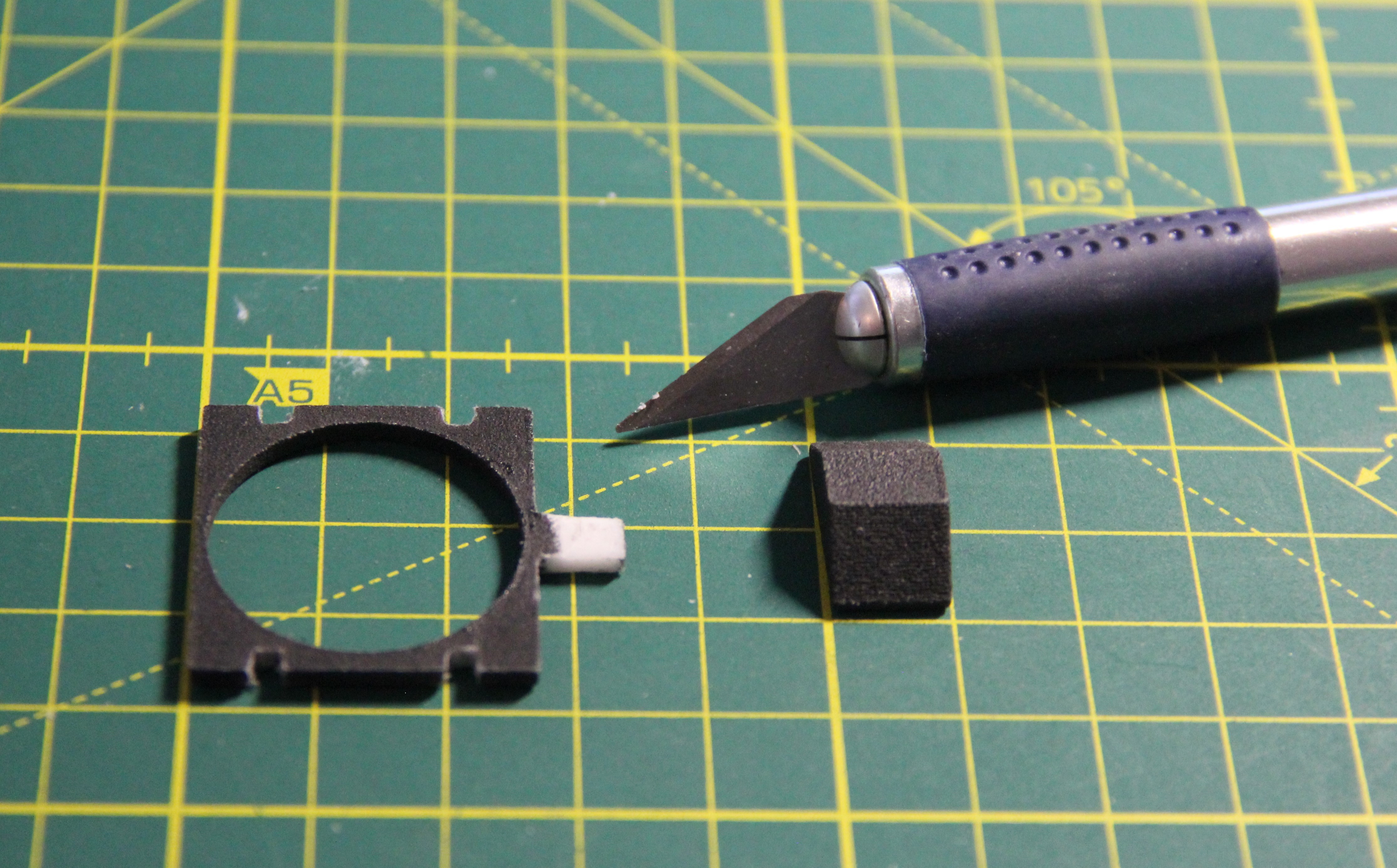
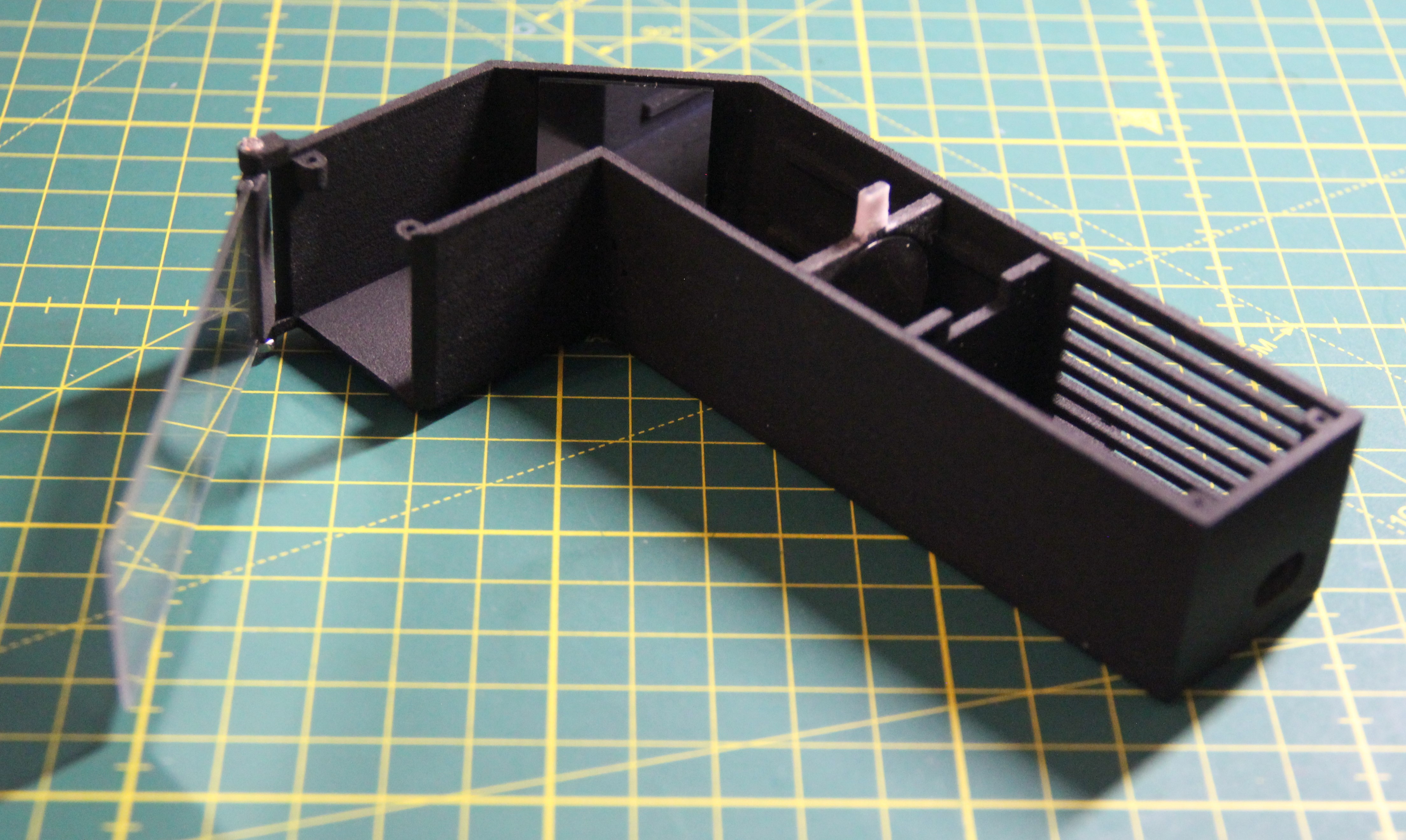
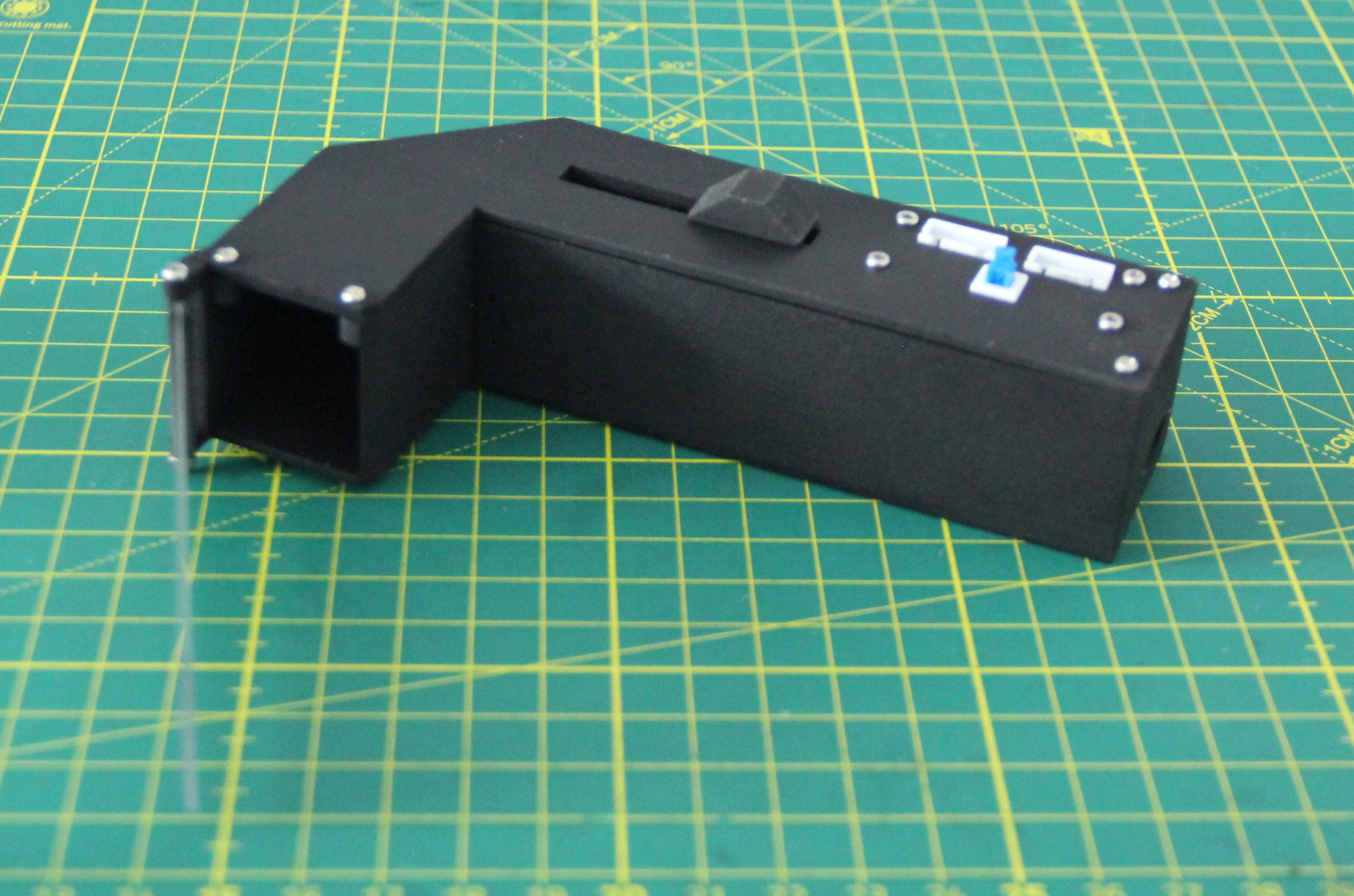
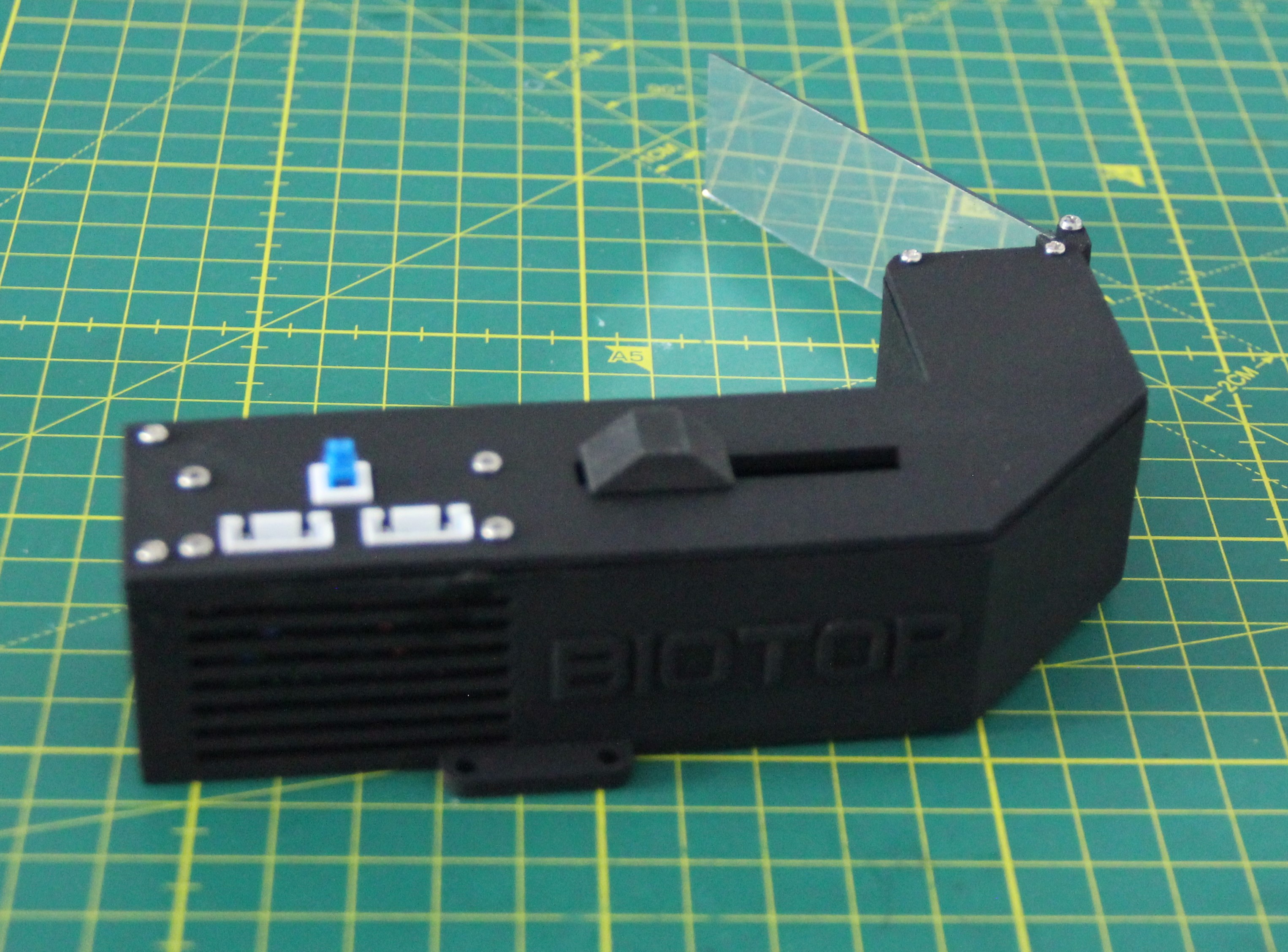
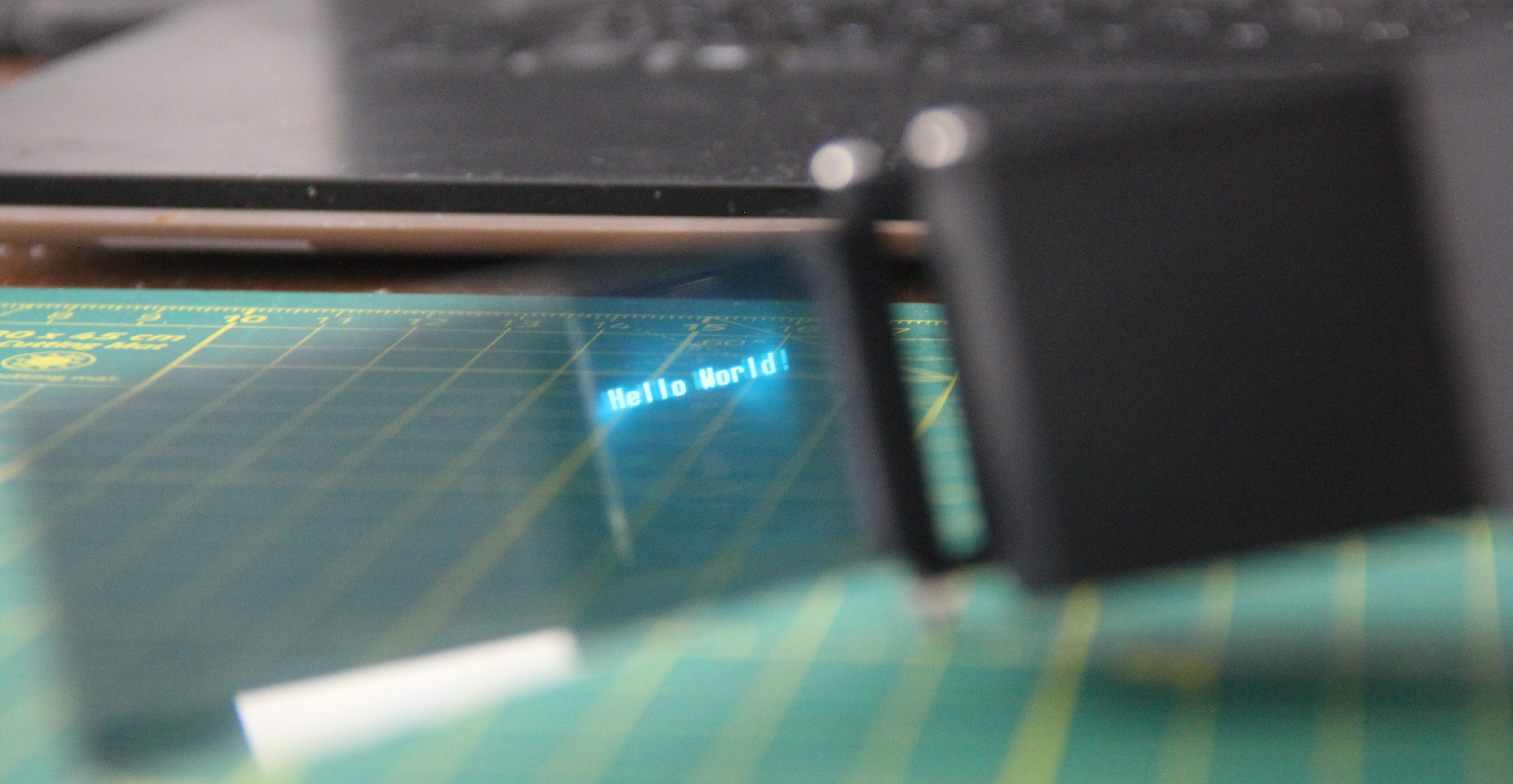
AR glasses overview
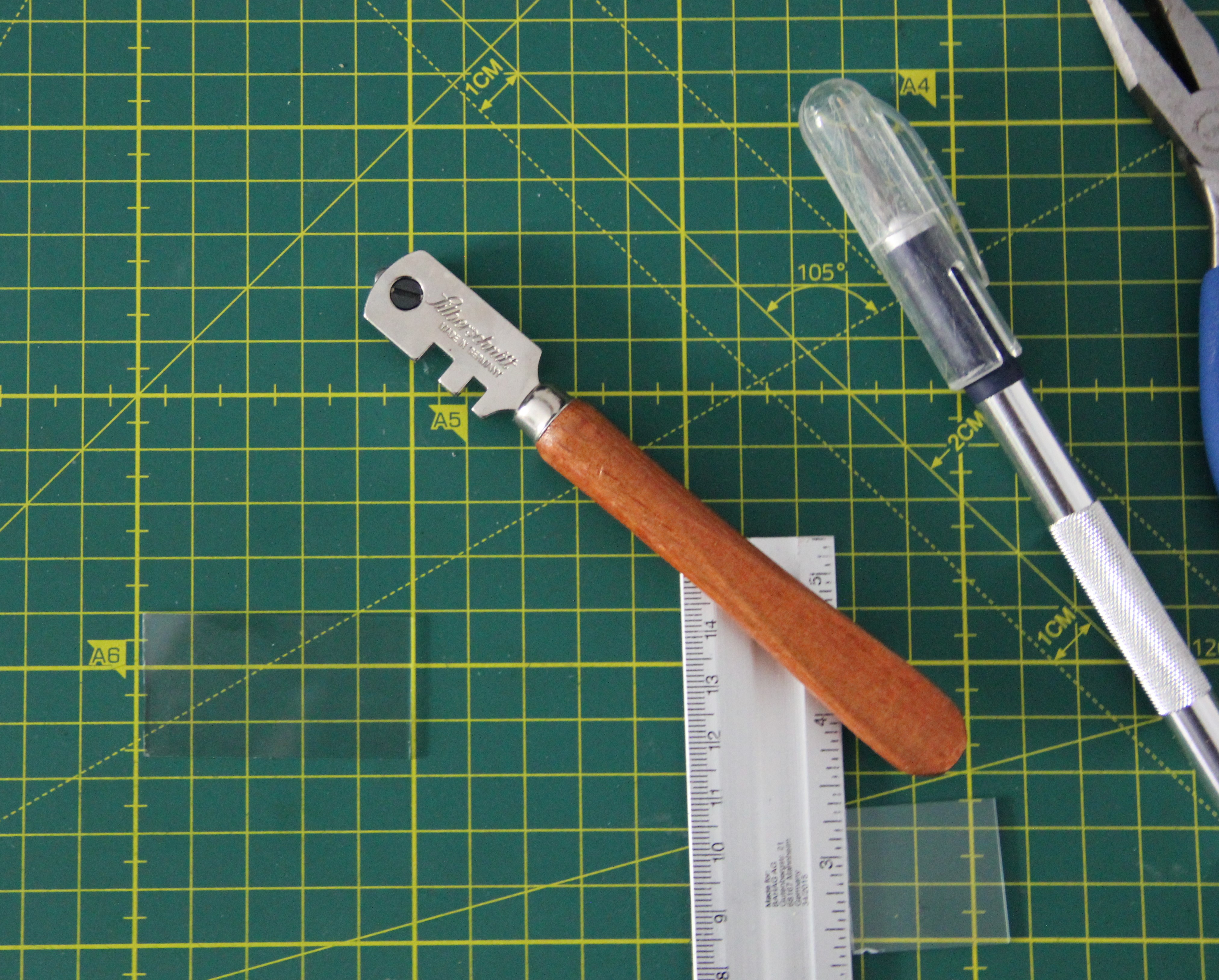
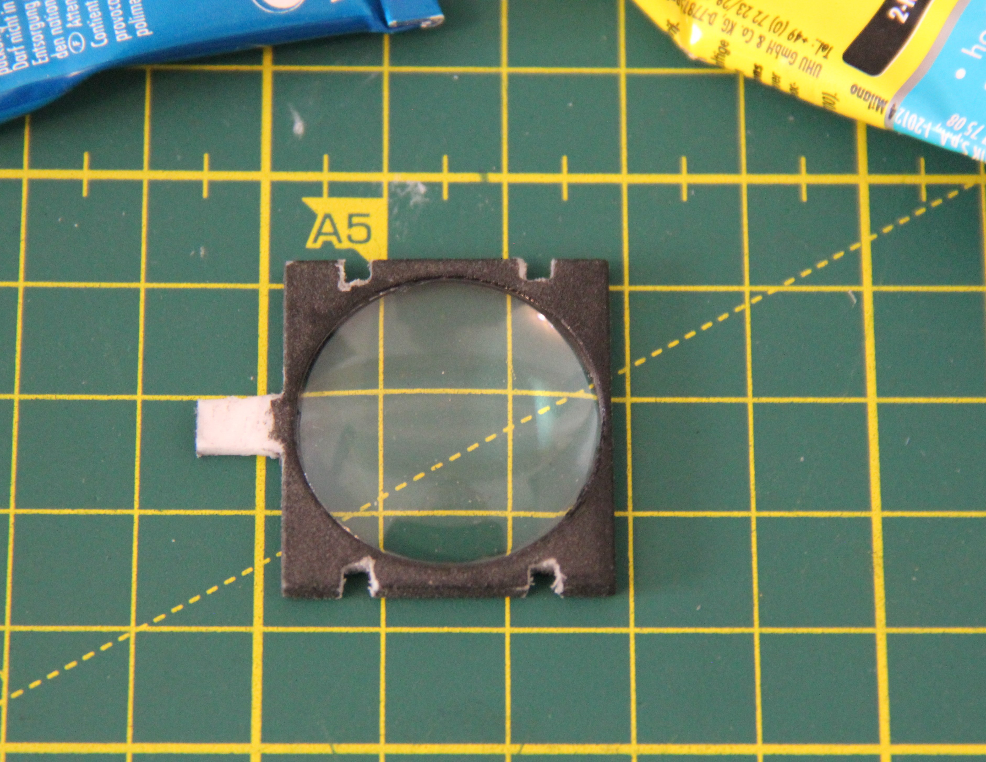
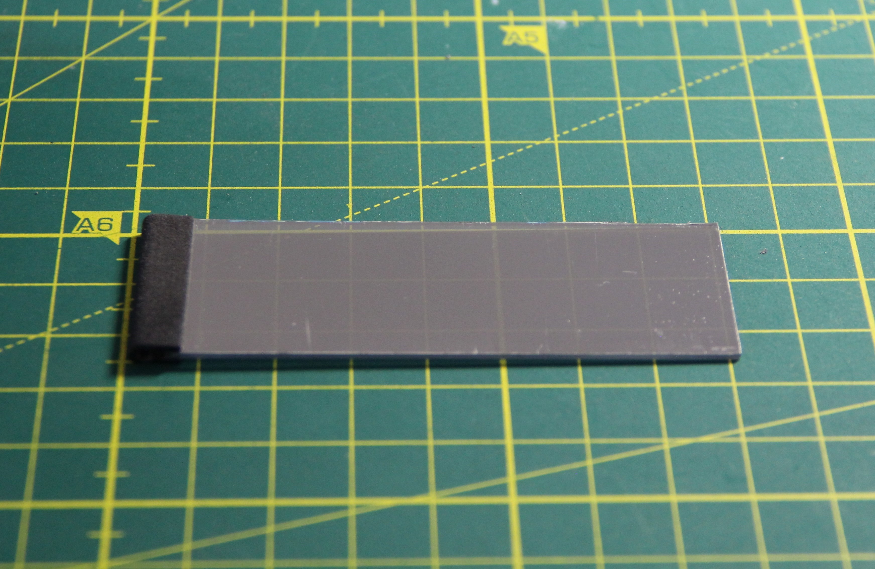
In my arrangement, the lens is between the OLED and the mirror. The lens is horizontally adjustable so that you can adjust the AR glasses to the user's visual acuity.
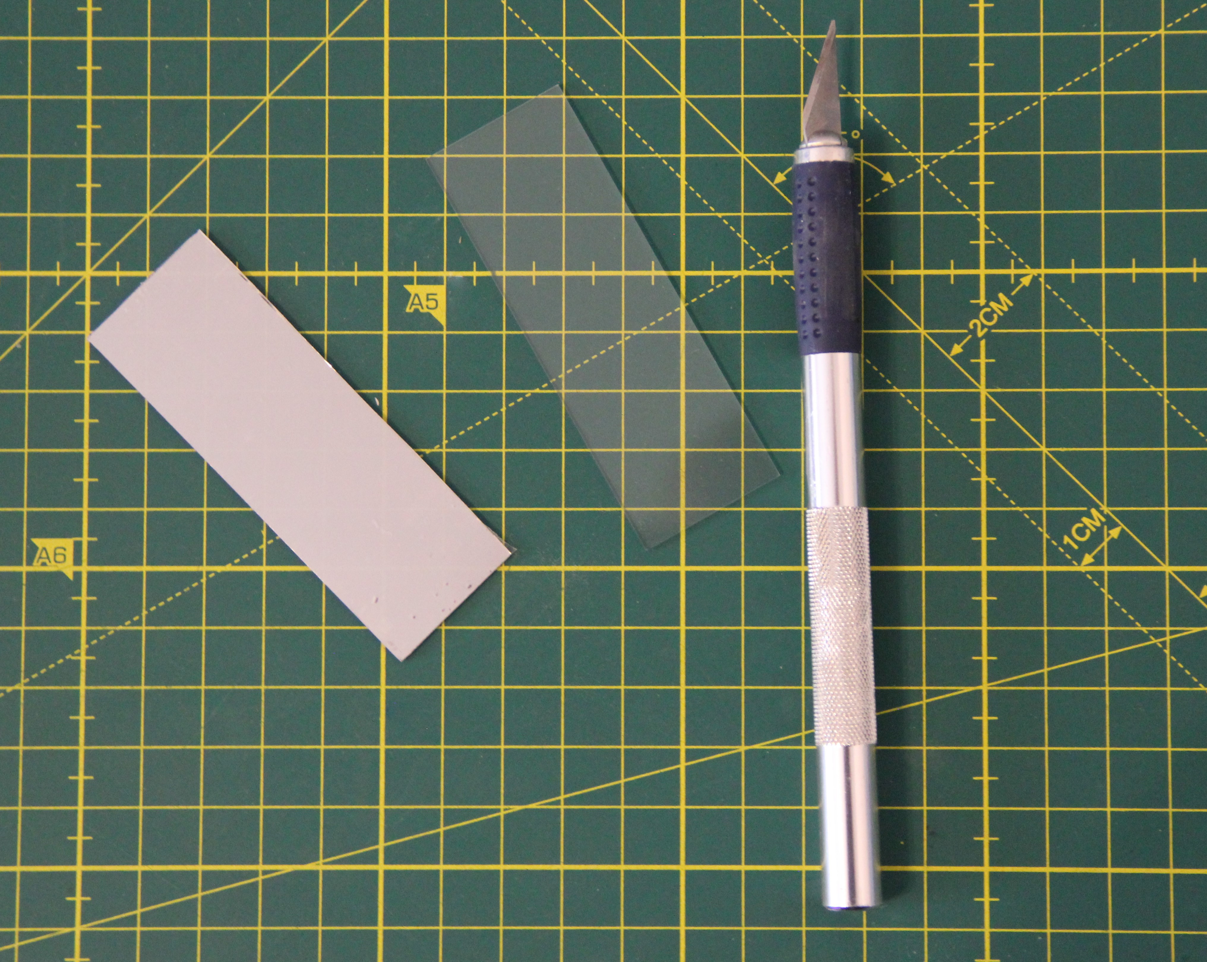
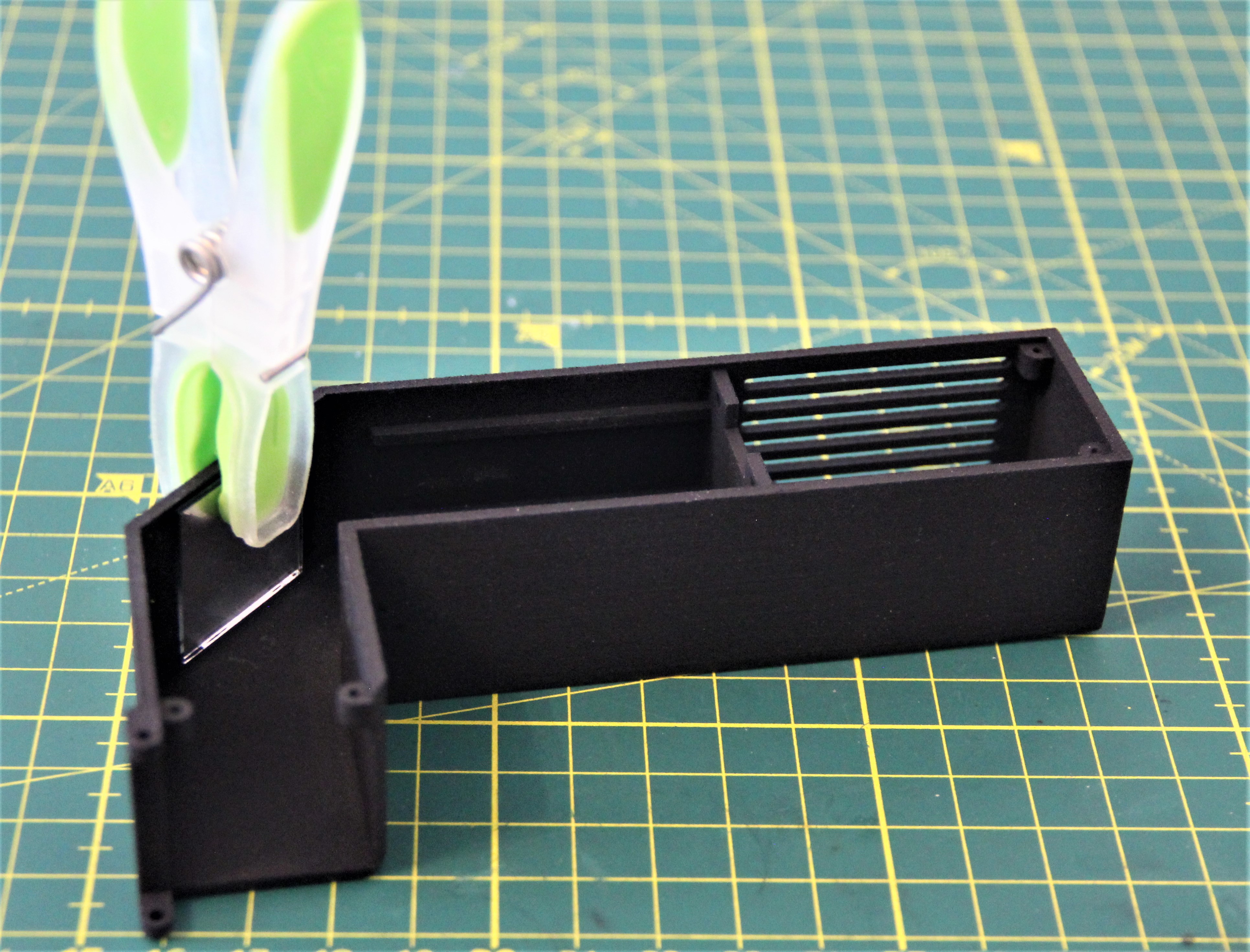
Ideally, the microscope slide would be semi-mirrored. Fortunately, there is an appropriate foil, which is actually intended for windows to protect interiors from too much sunlight. That's real hacking, isn't it?
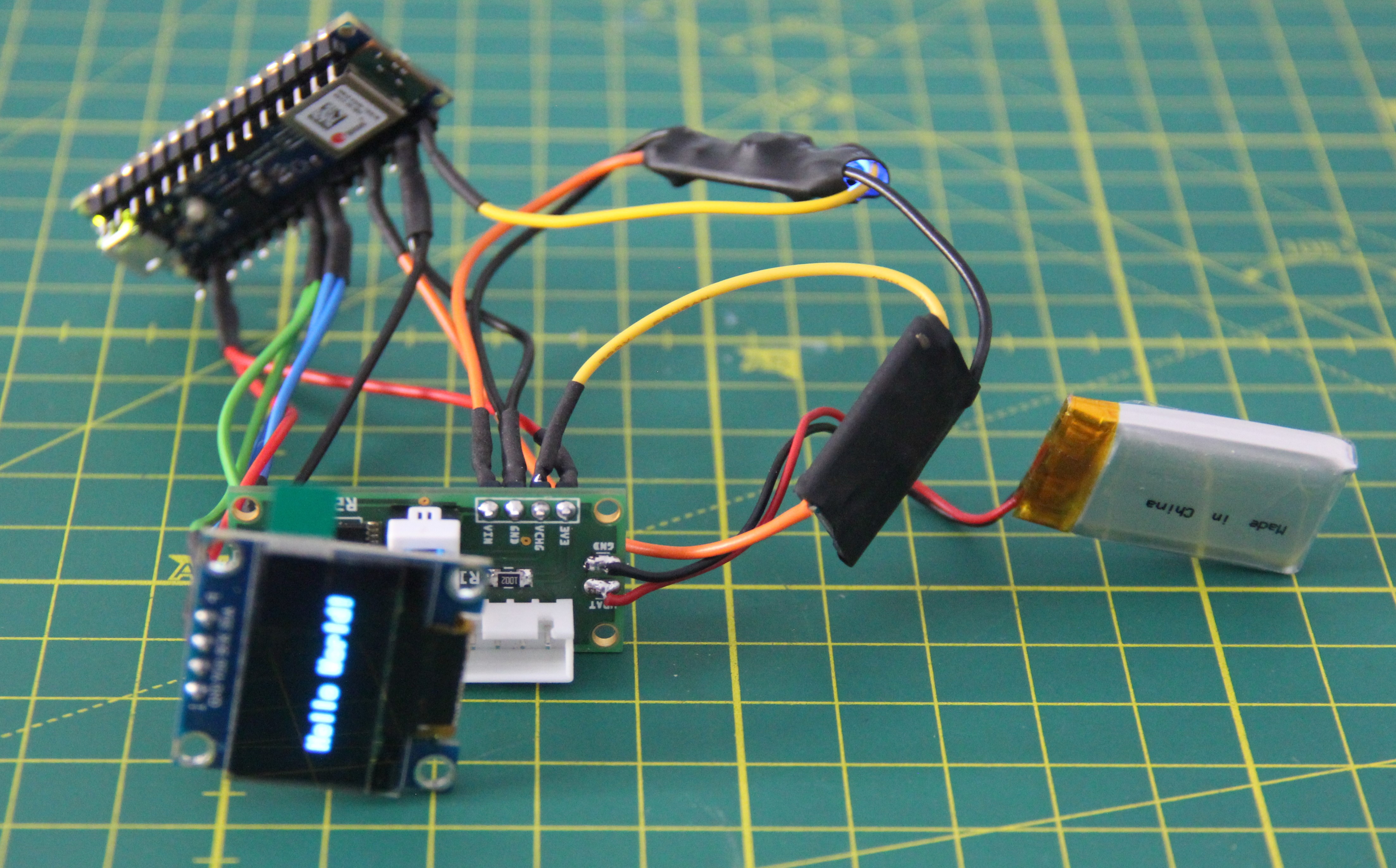
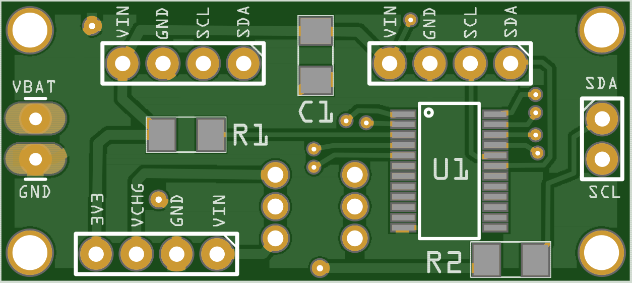
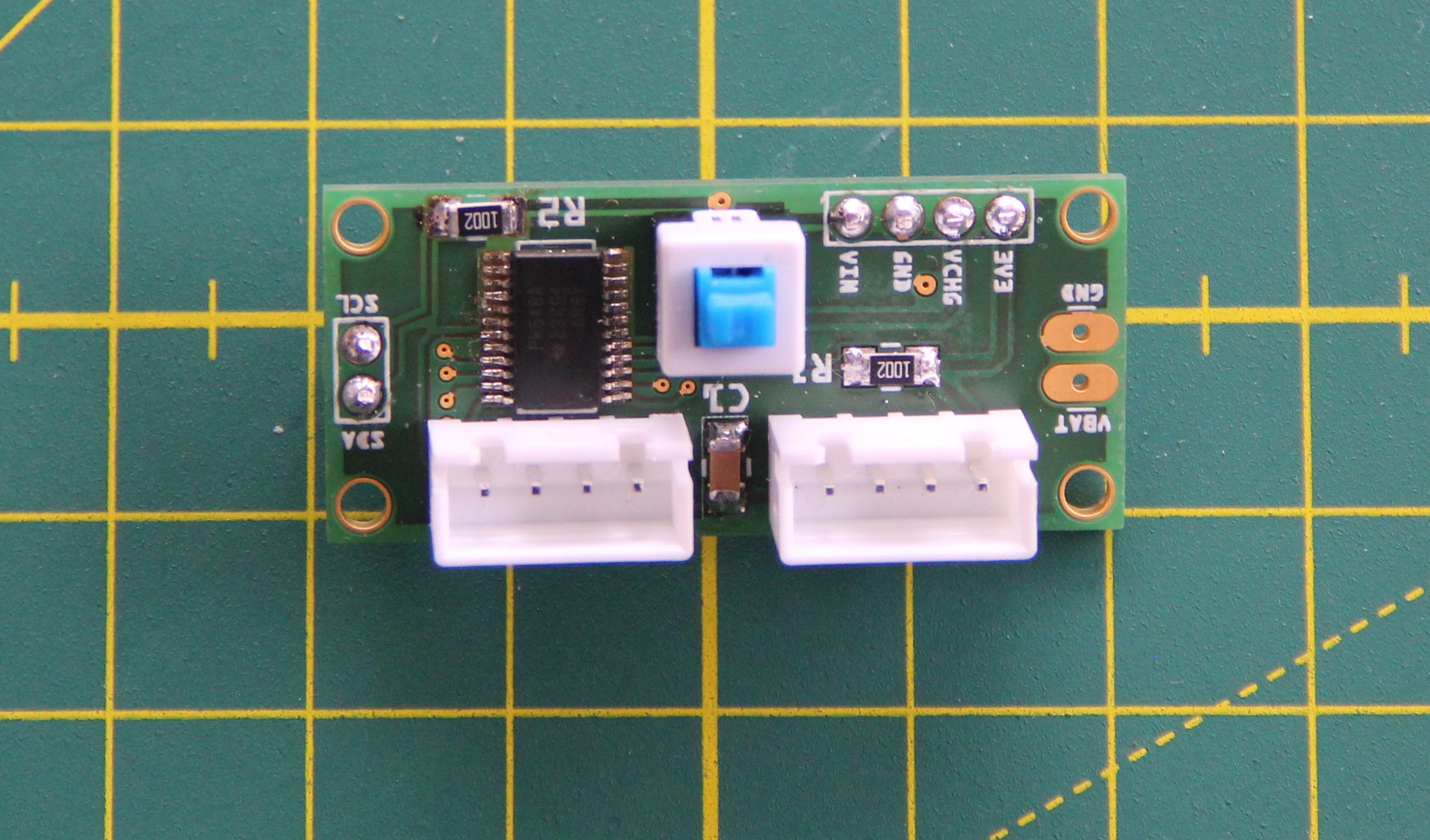
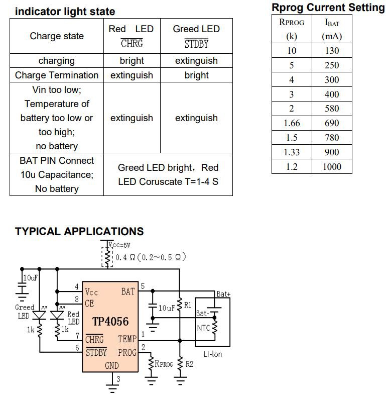
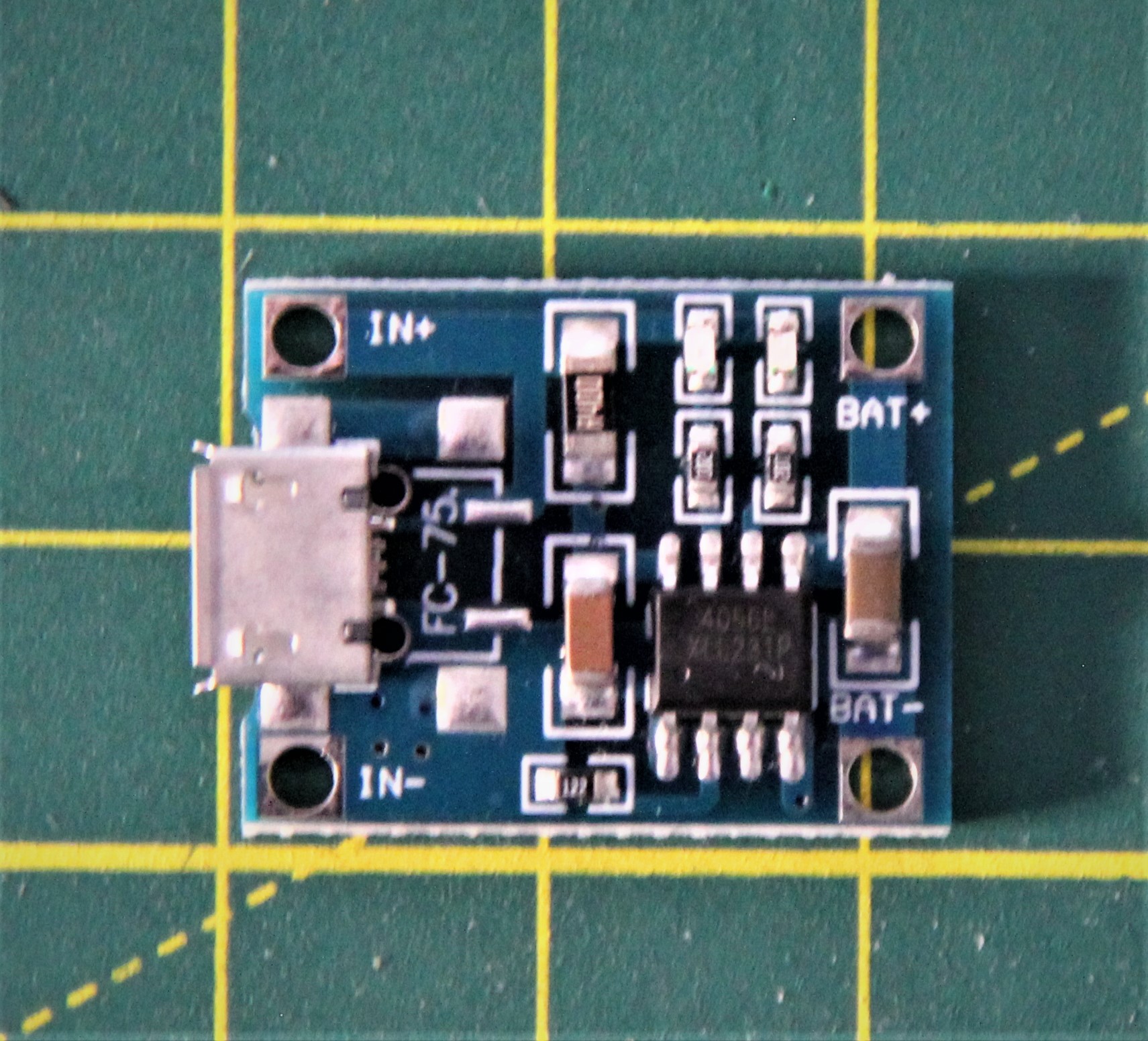
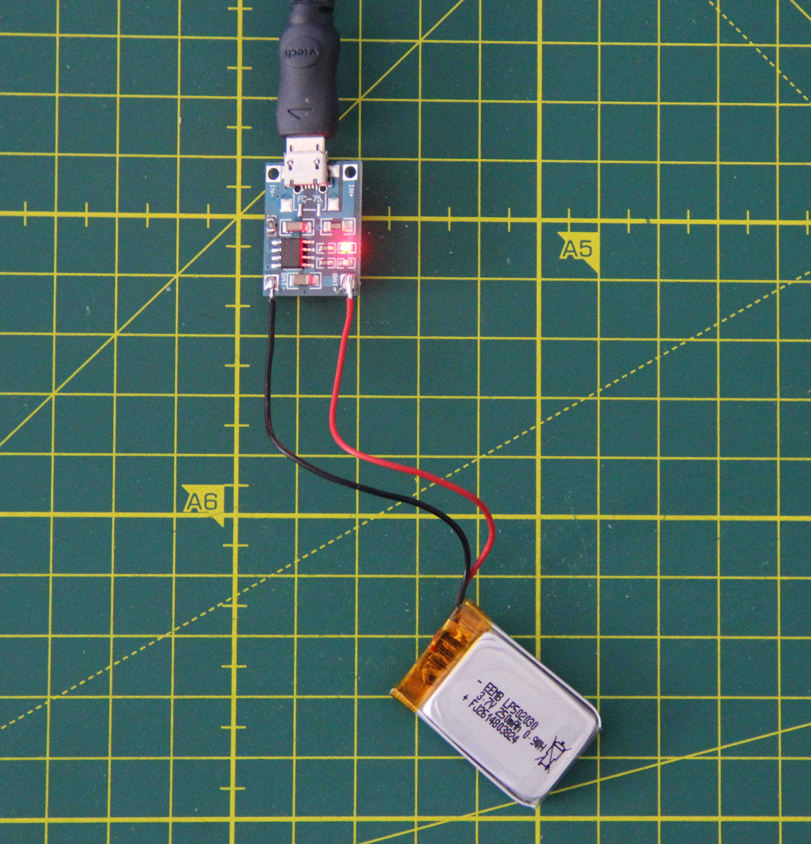
Power management
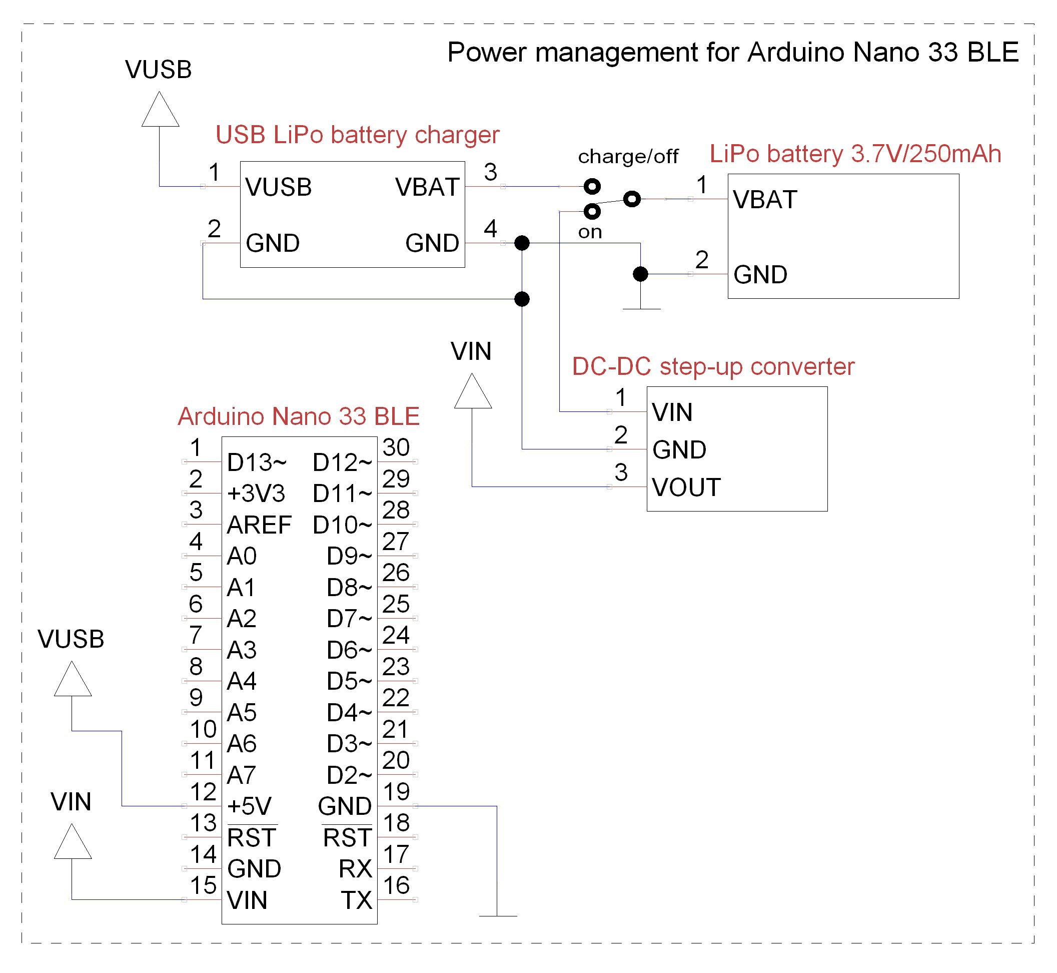
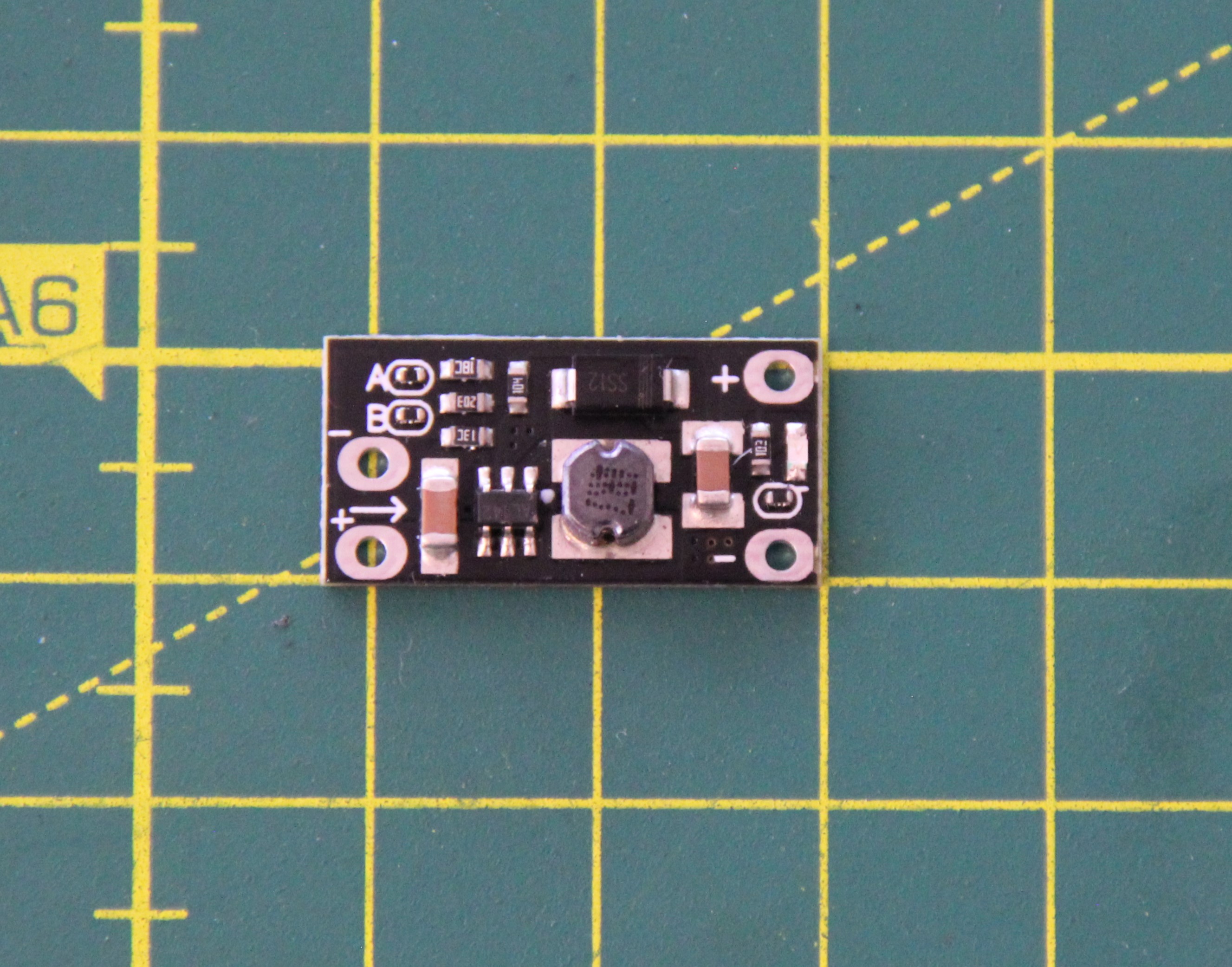
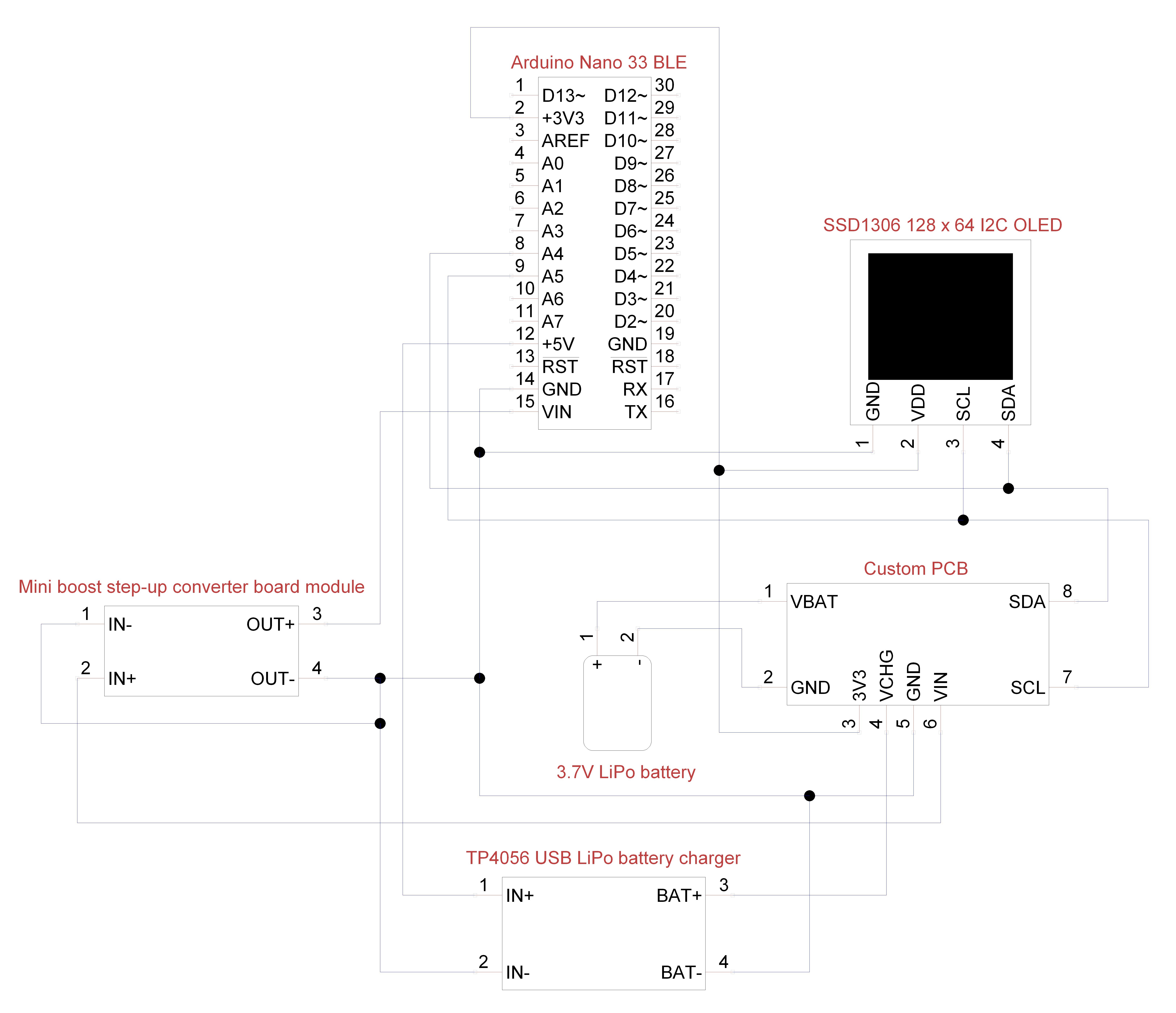
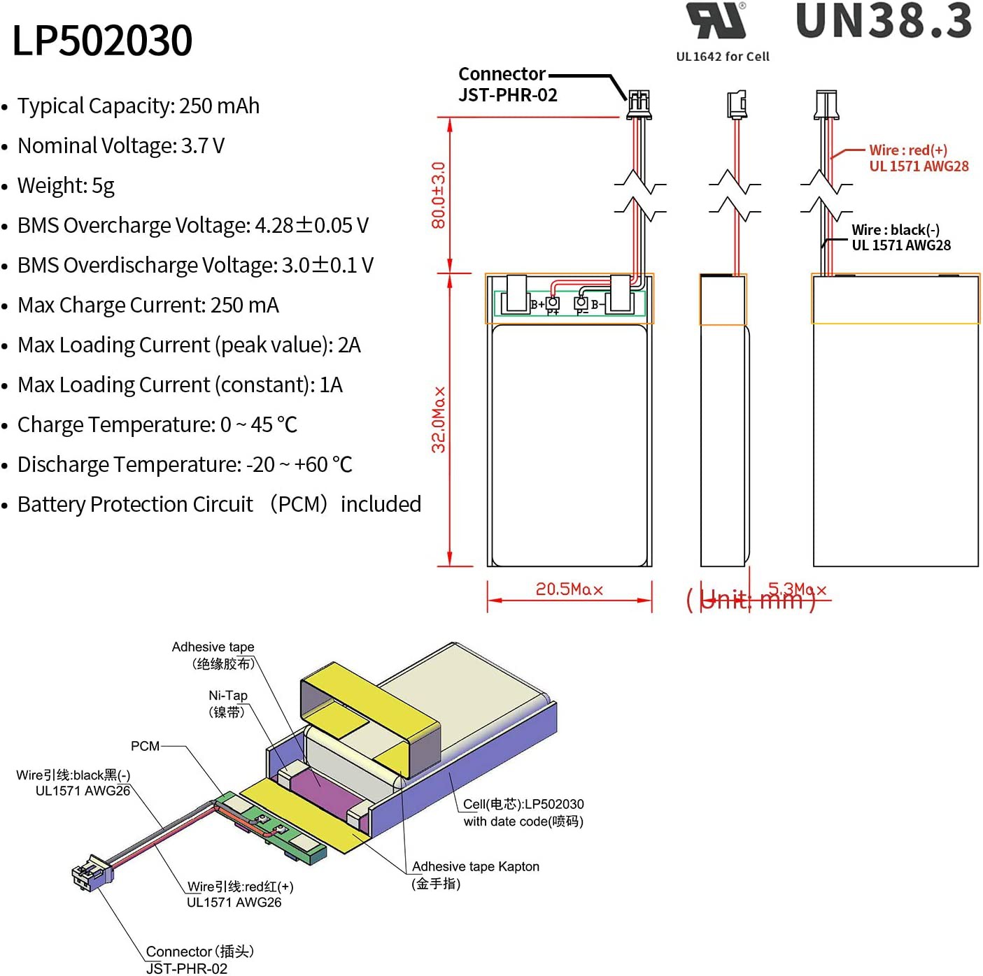
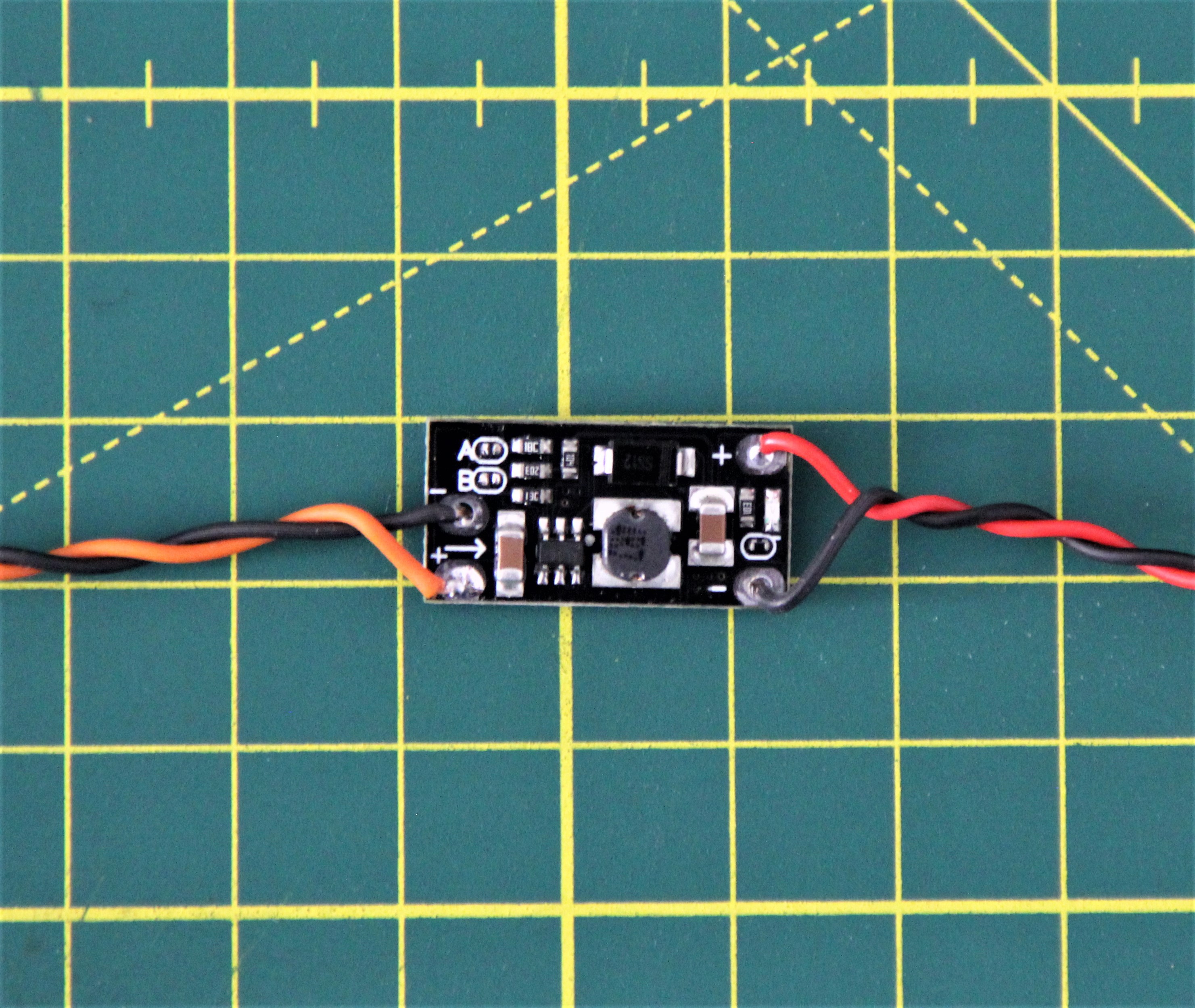
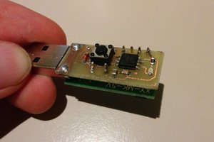
I am using an Arduino Nano 33 BLE for this project. It's the first time, I got my hands the first time on this evolution of the traditional Arduino Nano with a lot more powerful processor. The microcontroller is powered via the VIN pin. According to the schematic, the board uses an MPM3610 synchronous step-down converter, whose input voltage must be between 4.5 and 21 volts. So we can't power the microcontroller directly from a 3.7 V LiPo battery. Therefore we need appropriate power management. It consists of the 3.7 V LiPo battery, a switch between "charge" and "operate", a USB LiPo battery charger, and a step-up converter, which converts the 3.7V into 5V, which is then fed to the VIN pin.
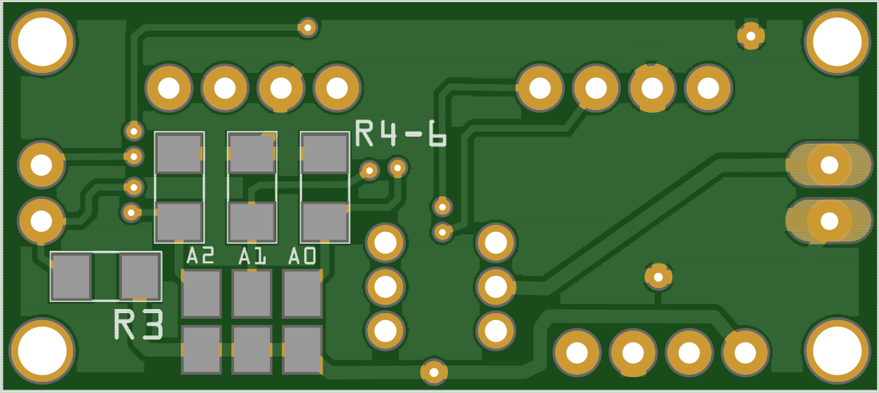
I2C multiplexer
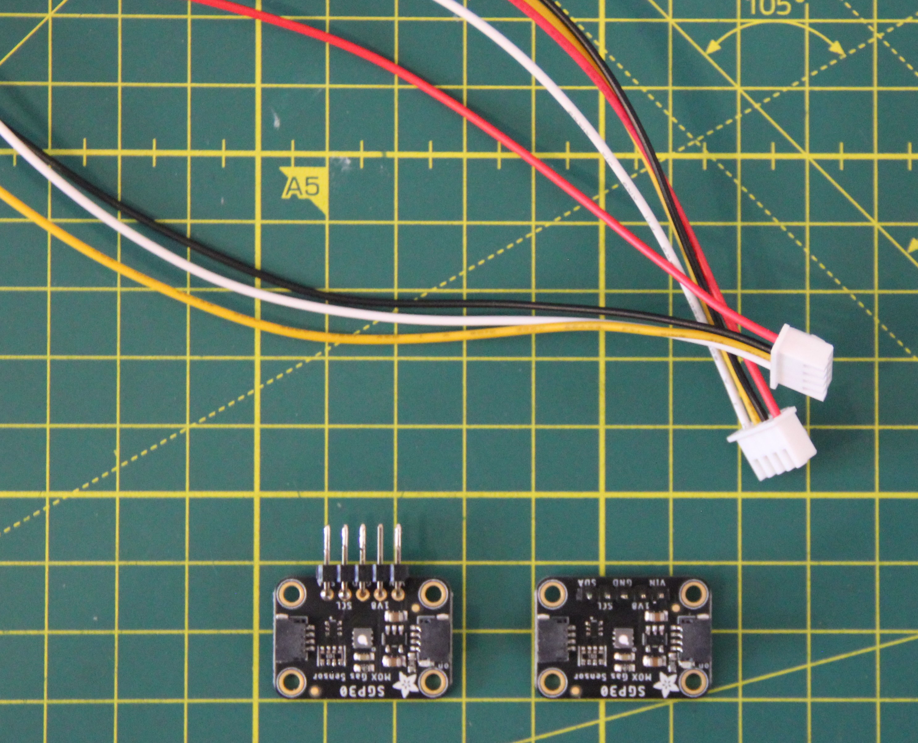
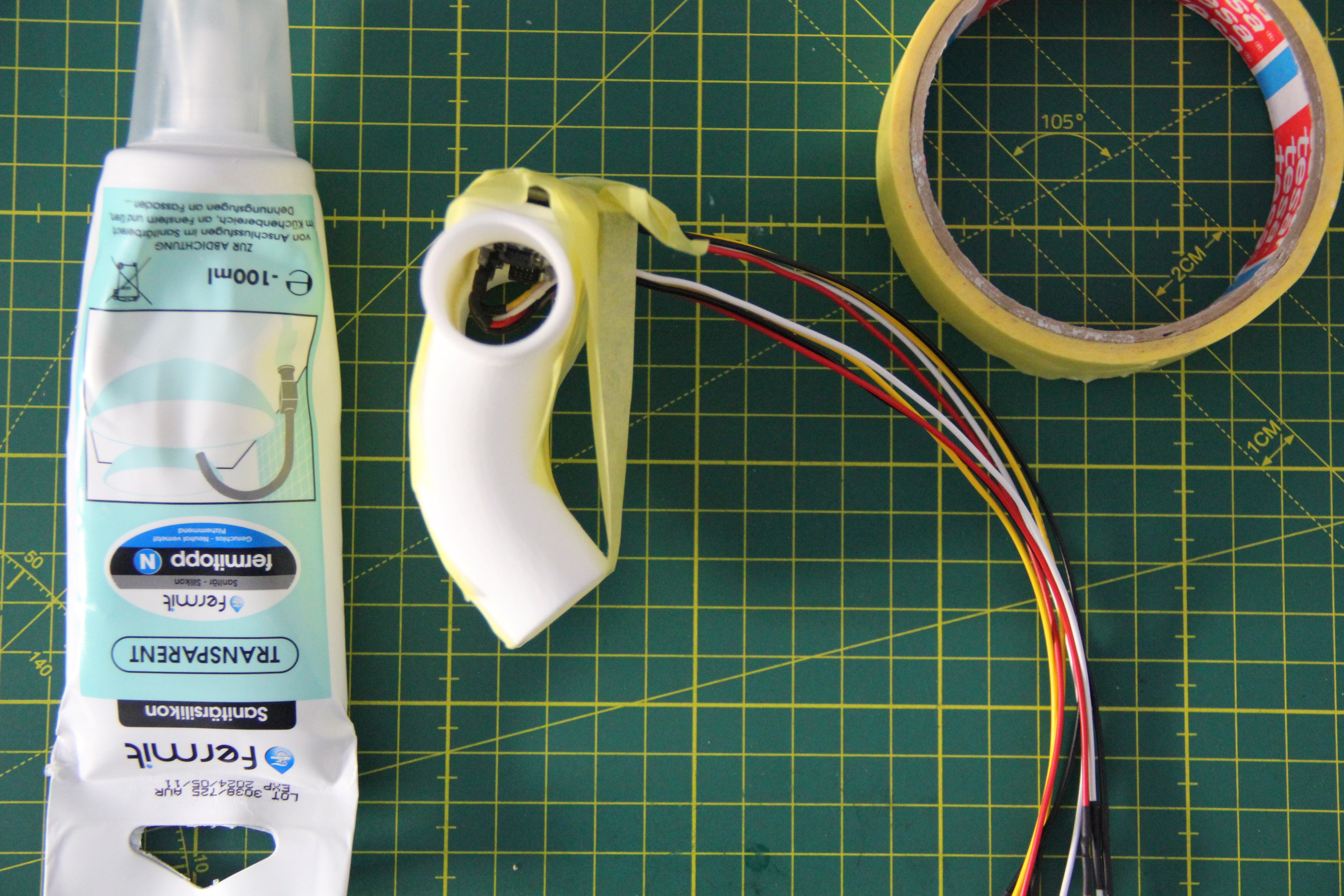
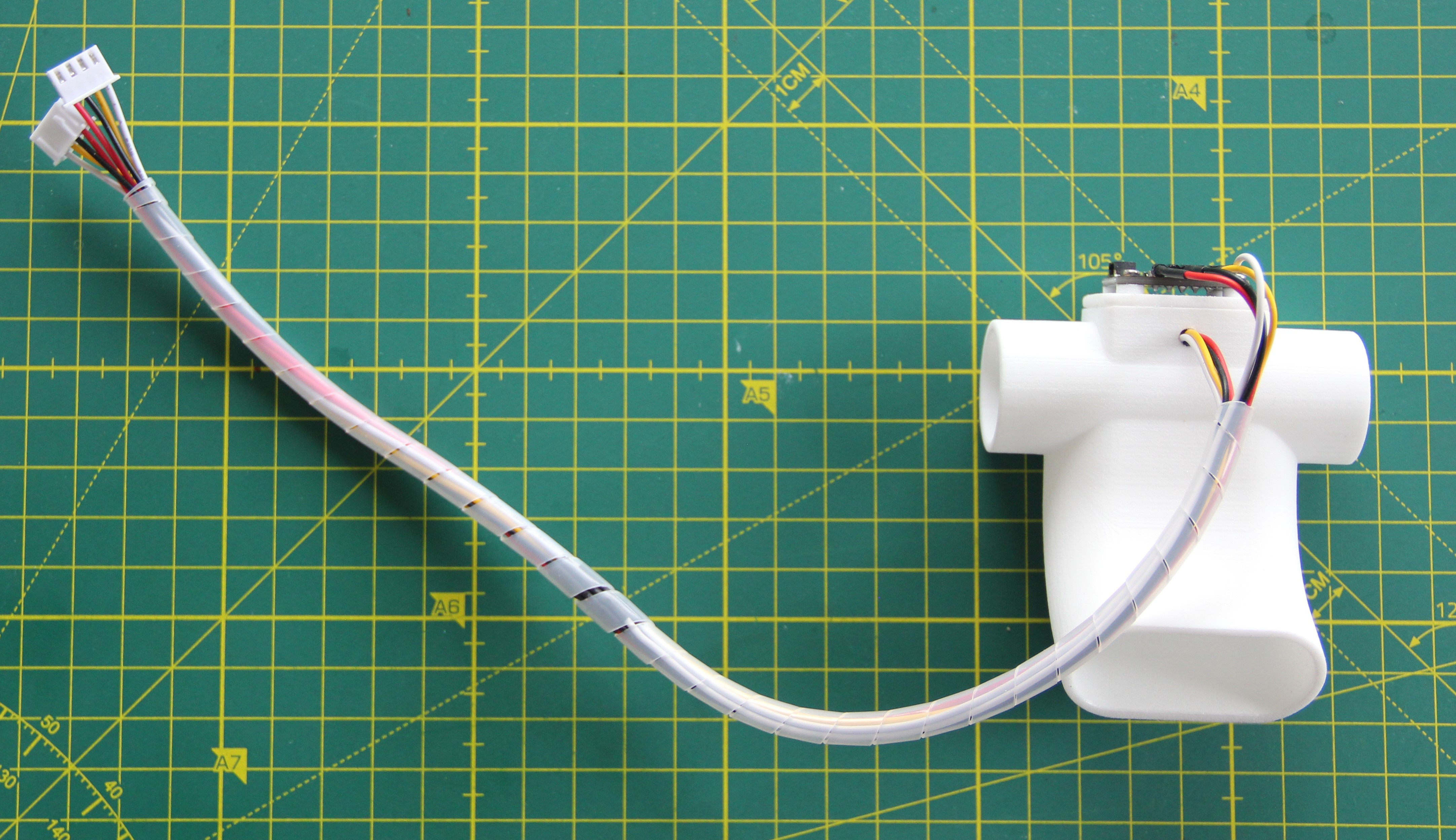
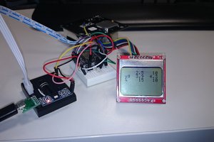
Two SGP30s are used as gas sensors. The sensor measures eCO2 (equivalent calculated carbon dioxide) concentration within a range of 400 to 60,000 ppm, and TVOC (Total Volatile Organic Compound) concentration within a range of 0 to 60,000 ppb. 400 ppm CO2 is the normal concentration in the air, and the sensor uses this value as a baseline. The disadvantage of this sensor is that it has a fixed I2C address (0x58) which cannot be changed. The problem can be solved with appropriate software, but I decided to use a hardware I2C multiplexer. Here the TCA9543A Low Voltage 2-Channel I2C Bus Switch from Texas Instruments is a good choice.

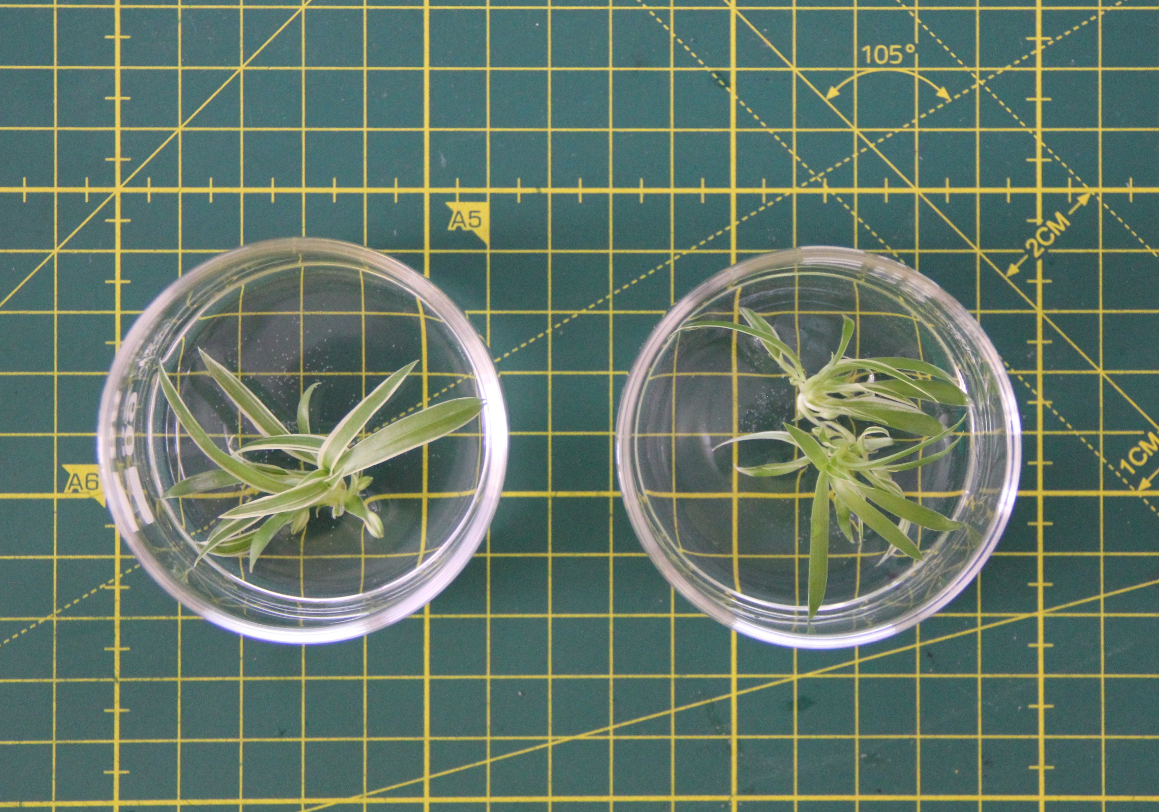
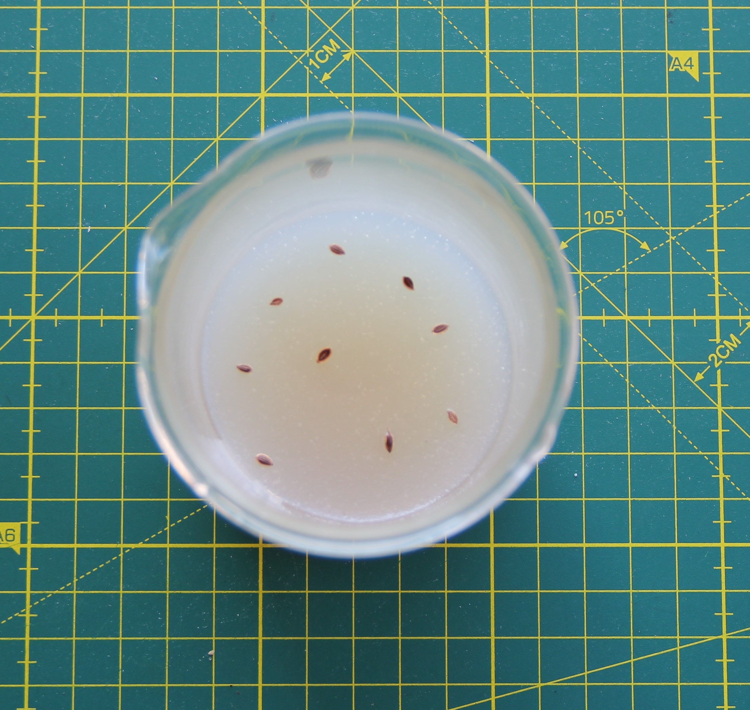
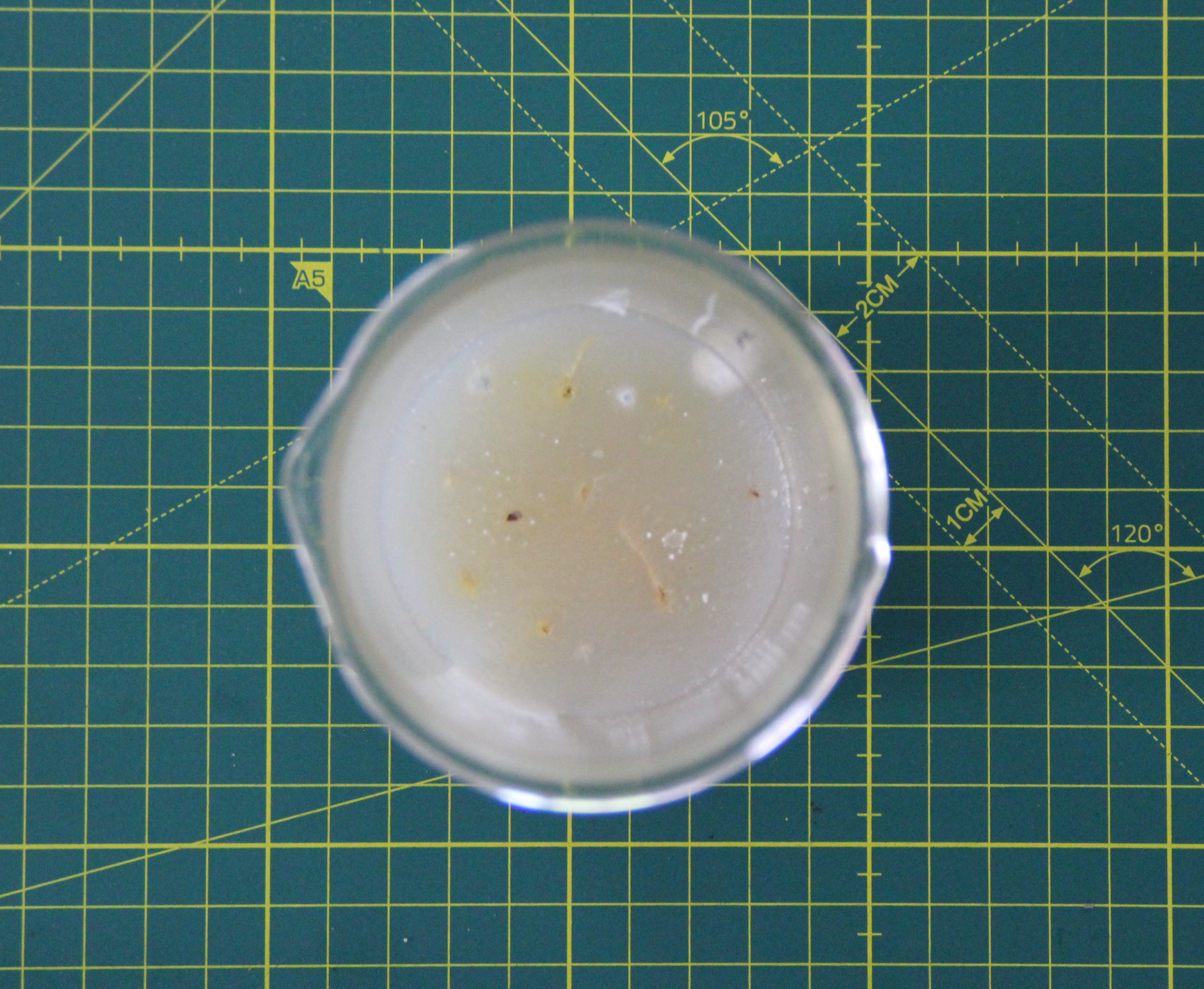
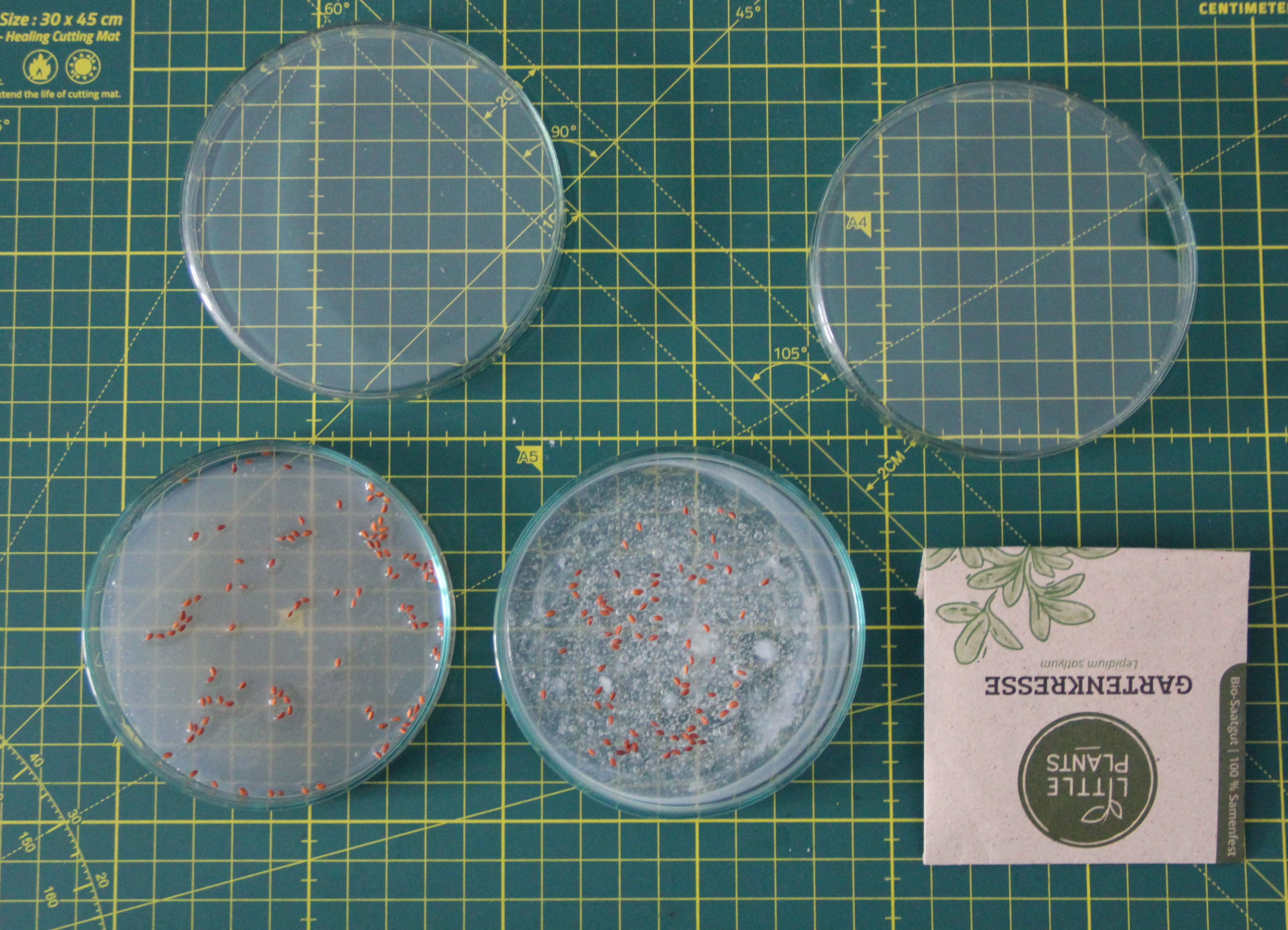
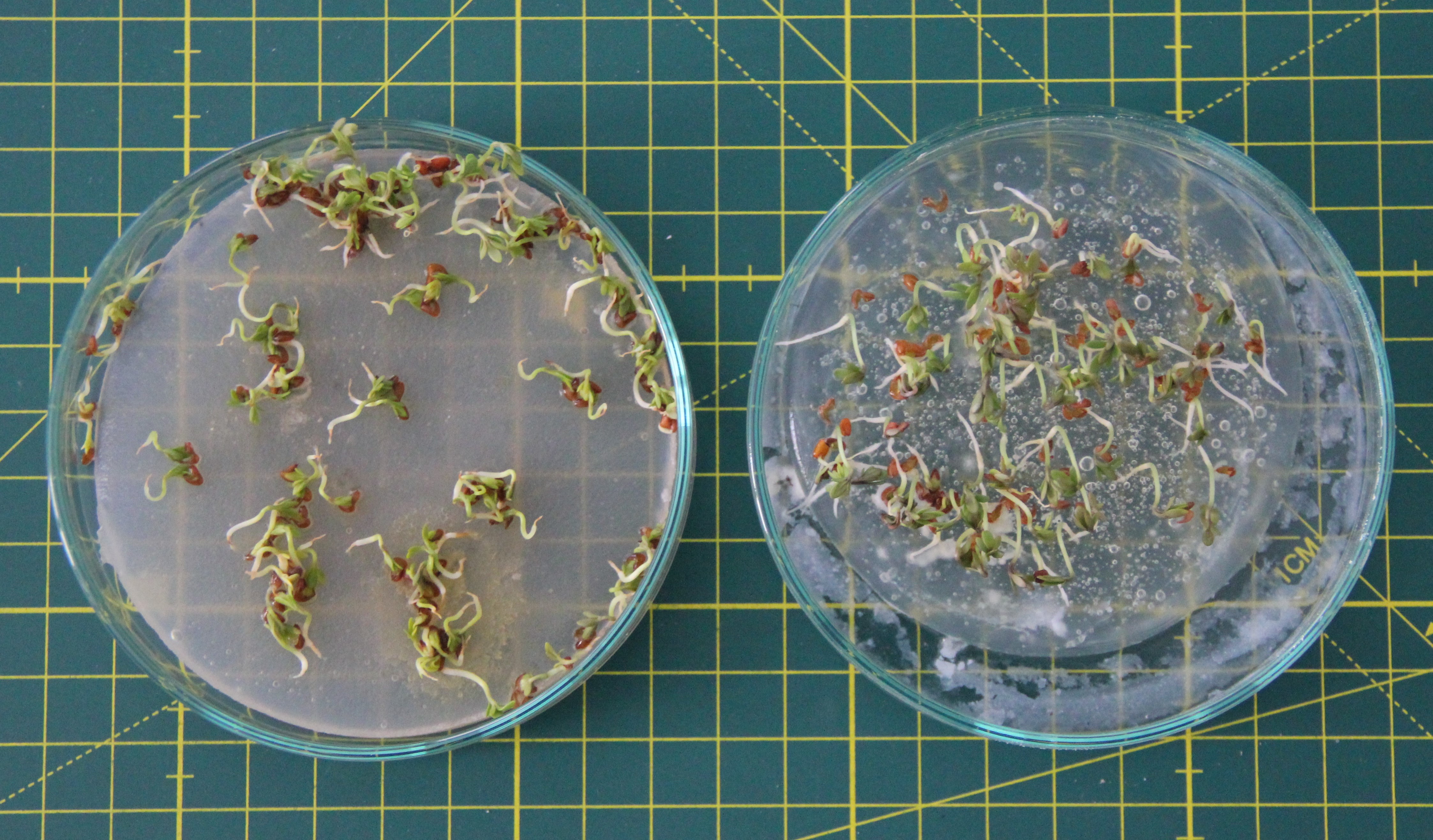
Agar instead of soil
As you move with the mask and bend forward, for example, simple plant soil is not the best choice, because...
Read more »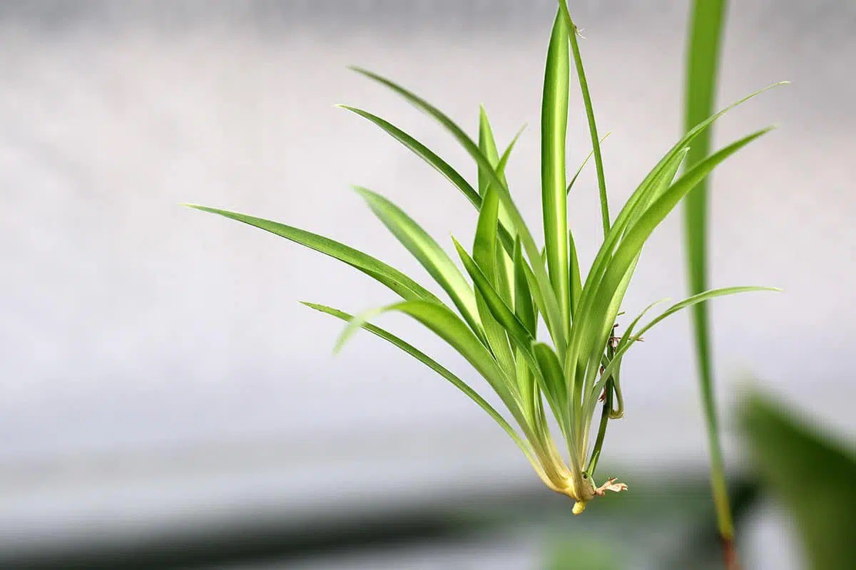

 k
k
 Open Green Energy
@ Bn0rmal Sure I will post results.